EP0856395A2 - Rotary press - Google Patents
Rotary press Download PDFInfo
- Publication number
- EP0856395A2 EP0856395A2 EP98250015A EP98250015A EP0856395A2 EP 0856395 A2 EP0856395 A2 EP 0856395A2 EP 98250015 A EP98250015 A EP 98250015A EP 98250015 A EP98250015 A EP 98250015A EP 0856395 A2 EP0856395 A2 EP 0856395A2
- Authority
- EP
- European Patent Office
- Prior art keywords
- pressure roller
- drive
- rotor
- rotary press
- roller unit
- Prior art date
- Legal status (The legal status is an assumption and is not a legal conclusion. Google has not performed a legal analysis and makes no representation as to the accuracy of the status listed.)
- Granted
Links
Images

Classifications
-
- B—PERFORMING OPERATIONS; TRANSPORTING
- B30—PRESSES
- B30B—PRESSES IN GENERAL
- B30B15/00—Details of, or accessories for, presses; Auxiliary measures in connection with pressing
- B30B15/0023—Drive arrangements for movable carriers, e.g. turntables
-
- B—PERFORMING OPERATIONS; TRANSPORTING
- B30—PRESSES
- B30B—PRESSES IN GENERAL
- B30B11/00—Presses specially adapted for forming shaped articles from material in particulate or plastic state, e.g. briquetting presses, tabletting presses
- B30B11/02—Presses specially adapted for forming shaped articles from material in particulate or plastic state, e.g. briquetting presses, tabletting presses using a ram exerting pressure on the material in a moulding space
- B30B11/08—Presses specially adapted for forming shaped articles from material in particulate or plastic state, e.g. briquetting presses, tabletting presses using a ram exerting pressure on the material in a moulding space co-operating with moulds carried by a turntable
-
- B—PERFORMING OPERATIONS; TRANSPORTING
- B30—PRESSES
- B30B—PRESSES IN GENERAL
- B30B15/00—Details of, or accessories for, presses; Auxiliary measures in connection with pressing
- B30B15/0076—Noise or vibration isolation means
Definitions
- the invention relates to a rotary press, especially for the production of tablets, with a Frame, a rotor with drive, at least one Pressure roller unit and a housing.
- Rotary presses consist of a frame, a rotor with drive, upper and lower rockers, which guide the upper and lower pressure rollers, a frame housing, corner connectors and a head plate consist.
- the forces occurring in the pressing process are about the stamp and the wings in the headstock and initiated the frame immediately and excite these membrane-like components by the pressing forces to vibrations, which in turn leads to considerable noise emissions to lead.
- a rotary press of the generic type is out the US-PS 3,891,375 previously known.
- the Base frame made of a rectangular frame, on the The rotor is mounted on the upper frame plate consists of brackets screwed onto the frame, which carry a control unit above the rotor.
- the pressure roller units are frame-like and on the side, screwed to the frame Carriers stored.
- the disadvantage here is the absorption of the compressive forces of the two pressure roller units from which the housing forming supports, which makes it suitable for high loads to deformation of the housing and related Vibrations and noise of the housing comes.
- the invention is therefore based on the object a rotary press of the generic type in this regard to improve the inclusion of the in the Forces introduced by pressure rollers is improved and which works with less vibrations and less noise.
- the invention provides that one the rotor with drive and the pressure roller unit absorbing solid, bending and torsion resistant base plate picked up from the base frame by means of elastic bearings is, the rigidity of this elastic Bearings and the mass of this complete press cell on each other are tuned that the natural frequency of this Vibration system in all six possible degrees of freedom much smaller than the lowest The lowest stamp engagement frequency occurring at the speed as the excitation frequency.
- the complete press cell will thereby excited supercritically during the pressing process.
- An impact from dynamic forces from the pressing process not on components of the rotary press arranged on the base plate almost does not take place. That’s how she works Tablet press low vibration and low noise and can nevertheless transmit large pressing forces.
- the housing is only connected to the base frame and compared to the base plate by means of smaller ones supported elastic bearing, the stiffness of the elastic bearing is chosen so that from the connected Mass and stiffness of the elastic The resulting natural frequency is much lower than the lowest punch engagement frequency. So there are almost no vibrations and therefore almost no noise from the press forces Vibrations excited parts, such as rotor with drive and pressure roller unit, transferred to the housing.
- the housing is designed so that the upper Head part of the machine receiving part of this housing extends over the entire height of the machine and the machine is limited on one vertical side.
- This housing segment is preferably used for recording the main electric drive, the incoming and outgoing connection lines, the supply units and the supply lines of the machine.
- a wall separates this supply side of the rotary press from the clean room side of the press cell.
- the elastic bearings are as two metallic bearing elements and one connecting them elastic buffer trained.
- Such elastic bearings are under the SCHWINGMETALL brand from the company Continental.
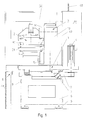
- the rotary press comprises a massive, bending and torsionally rigid base plate 1, a rotor 2, a Pressure roller unit 3 and a drive motor 4, the are stored on the solid base plate 1, and a base frame 6 standing on elastic feet 5, on which the massive base plate 1 by means of elastic Bearing 7 is mounted, and a surrounding these components Housing 8 that by means of smaller elastic bearings 9 is connected to the base frame 6.
- a bearing bush 11 for the axis 12 of here Not shown rotor 2 arranged on the solid base plate 1 a bearing bush 11 for the axis 12 of here Not shown rotor 2 arranged.
- the axis 12 of the rotor 2 carries on the underside of the base plate 1 a toothed belt pulley 13.
- the pressure roller unit 3 is included upper and lower pressure roller 14, 15 adjustable stored.
- the massive one Base plate 1 attached drive motor 4 with on the Bottom toothed belt pinion 16, with a Toothed belt 17 around the toothed belt pulley 13 for the Rotor 2 and the toothed belt pinion 16 put around and is tensioned by a spring washer 18.
- elastic bearings 7 support the massive base plate 1 on the base frame 6 shown in FIG. 1 elastic bearings 7 are made of two metallic bearing elements 19, 20 and an elastic connecting them Buffer 21 formed.
- the elastic bearings 7 are under the brand SCHWINGMETALL from Continental customary.
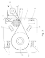
- Fig. 3 shows the bottom view of the massive, bending and torsionally rigid base plate 1 with the four elastic bearings 7, the rotor 2 driving large toothed belt pulley 13, which from the drive motor 4th driven toothed belt pinion 16 and the toothed belt 17 exciting clamping washer 18.
- Under one Angle of approximately 35 ° to the longitudinal axis 22 of the base plate 1 extend elongated holes 23, the receiving and Storage each serve a pressure roller unit 3, the is described in more detail below with reference to FIG. 4.
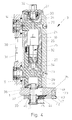
- the pressure roller unit 3 of the rotary press exists from a solid, cylindrical section Guide column 10, in its cylindrical Interior 26 is also cylindrical and hollow trained upper pressure roller receptacle 24 and one cylindrical and internally hollow lower pressure roller holder 25 are slidably mounted, the upper and lower pressure roller receptacles 24, 25 also are solid and stable.
- the guide column 10 In the upper area the guide column 10 are an adjustment drive 27 for the upper pressure roller 14 and in the central area of the Guide column 10, an actuator 28 for the lower Pressure roller 15 arranged.
- the upper adjustment drive 27 is used to adjust the upper pressure roller 14 and hence the immersion depth of the from the upper pressure roller 14 acted upon upper stamp 30 and for common i.e. parallel adjustment of upper and lower Pressure roller 14 or 15 with a fixed distance and thus to Press zone adjustment.
- the adjustment drive 28 for the lower pressure roller 15 is used to adjust the Tablet thickness relative to upper pressure roller 14.
- the two adjustment drives 27, 28 each exist from a geared motor 32 with drive spindle 33, the engages in a spindle nut 34 which is fixed to the Pressure roller receptacle 24, 25 is connected.
- the upper pressure roller receptacle 24 with the pressure roller axis 29 for the upper pressure roller 14 and the lower pressure roller holder 25 with the pressure roller axis 29 for the lower pressure roller 15 within the Guide column 10 can be moved adjustable.
- the pressure roller unit 3 is with its guide column 10 standing vertically on the solid base plate 1 stored and working horizontally Adjustment drive 35 movable. Inside the lower one The end of the guide column 10 is a truncated cone Mounting flange 36 by means of three distributed around the circumference Ring segments 46 set. In the mounting flange 36 is within the central axis of the Guide column 10 a tie rod 37 screwed in a neck 38 at the lower end of the truncated cone Fastening flange 36 penetrates the is movable within an elongated hole 23 which in the massive base plate 1 is introduced.
- the tie rod 37 is below the base plate 1 of the wedge 39 within of the stop ring 40 penetrated by means of a Dome piece 41 held by the T-head of the tie rod 37 is.
- the wedge 39 is by means of a screw spindle 42 detachable and pullable, which at the free end in one vertical bolts 47 fixed in the base plate 1 rotatable and horizontally immovable.
- To the The screw spindle 42 is locked on a spindle head 43 rotated until the neck 38 of the Mounting flange 36 and the stop ring 40 on strike the left end of slot 23. It presses the spindle 42 under the action of a compression spring 44 Tip 45 against the tie rod 37.
- the wedge 39 moved to the left so that the guide column 10 by means of the tie rod 37 firmly on the top of the Base plate 1 of the rotary tablet press is seated.
- Fig. 1 shows one in Fig. 1 on the left below the base plate 1 and next to the base frame 6 and extending right behind the pressure roller unit 3 Partition 48 which seals the housing 8 on all sides encloses.
- the partition 48 can be an on-site wall and allows the rotary press to be subdivided in one in Fig. 1 to the right of the partition 48 a multifunction column 51 and in one below the base plate 1 located supply area and a clean room area located above the base plate 1 with that of the rotor 2 and the pressure roller unit 3 press cell formed.
- the clean room area the press cell is through the base plate 1, which is in Fig. 1 wall 49 of the multifunction column shown on the left 51, the head 50 and the partition 48 from the service area Cut.
- the coverage area be used regardless of the clean room area, around the bottom and back of the rotary press located mechanical and electrical drives and Supply units from outside the clean room too serve.
- the energy supply to the rotary press can from above or below directly into the multifunction column 51 take place.
Landscapes
- Engineering & Computer Science (AREA)
- Mechanical Engineering (AREA)
- Press Drives And Press Lines (AREA)
- Medical Preparation Storing Or Oral Administration Devices (AREA)
- Presses And Accessory Devices Thereof (AREA)
- Glanulating (AREA)
- Battery Electrode And Active Subsutance (AREA)
Abstract
Description
Die Erfindung bezieht sich auf eine Rundlaufpresse, insbesondere zur Herstellung von Tabletten, mit einem Gestell, einem Rotor mit Antrieb, mindestens einer Druckrolleneinheit und einem Gehäuse.The invention relates to a rotary press, especially for the production of tablets, with a Frame, a rotor with drive, at least one Pressure roller unit and a housing.
Bekannt sind Rundlaufpressen, die aus einem Gestell, einem Rotor mit Antrieb, oberen und unteren Schwingen, welche die obere und die untere Druckrolle führen, einem Gestellgehäuse, Eckverbindern und einer Kopfplatte bestehen. Die im Preßprozeß auftretenden Kräfte werden über die Stempel und die Schwingen in die Kopfplatte und das Gestell unmittelbar eingeleitet und erregen diese membranartigen Bauteile durch die Preßkräfte zu Schwingungen, die damit zu erheblichen Lärmemissionen führen. Rotary presses are known which consist of a frame, a rotor with drive, upper and lower rockers, which guide the upper and lower pressure rollers, a frame housing, corner connectors and a head plate consist. The forces occurring in the pressing process are about the stamp and the wings in the headstock and initiated the frame immediately and excite these membrane-like components by the pressing forces to vibrations, which in turn leads to considerable noise emissions to lead.
Eine Rundlaufpresse der gattungsgemäßen Art ist aus der US-PS 3,891,375 vorbekannt. Hierbei besteht das Basisgestell aus einem rechteckigen Rahmen, auf dessen oberer Rahmenplatte der Rotor gelagert ist.Das Gehäuse besteht aus auf das Rahmengestell aufgeschraubten Trägern, die oberhalb des Rotors eine Steuereinheit tragen. Die Druckrolleneinheiten sind rahmenartig ausgebildet und an seitlichen, an das Rahmengestell angeschraubten Trägern gelagert.A rotary press of the generic type is out the US-PS 3,891,375 previously known. Here is the Base frame made of a rectangular frame, on the The rotor is mounted on the upper frame plate consists of brackets screwed onto the frame, which carry a control unit above the rotor. The pressure roller units are frame-like and on the side, screwed to the frame Carriers stored.
Nachteilig hierbei ist die Aufnahme der Druckkräfte der beiden Druckrolleneinheiten von den das Gehäuse bildenden Trägern, wodurch es bei hohen Belastungen zu Verformungen des Gehäuses und damit verbundenen Schwingungen und Geräuschen des Gehäuses kommt.The disadvantage here is the absorption of the compressive forces of the two pressure roller units from which the housing forming supports, which makes it suitable for high loads to deformation of the housing and related Vibrations and noise of the housing comes.
Die Erfindung liegt von daher die Aufgabe zugrunde, eine Rundlaufpresse der gattungsgemäßen Art dahingehend zu verbessern, daß die Aufnahme der in die Druckrollen eingeleiteten Kräfte verbessert ist und die schwingungs- und geräuscharmer arbeitet.The invention is therefore based on the object a rotary press of the generic type in this regard to improve the inclusion of the in the Forces introduced by pressure rollers is improved and which works with less vibrations and less noise.
Zur Lösung dieser Aufgabe sieht die Erfindung vor, daß eine den Rotor mit Antrieb und die Druckrolleneinheit aufnehmende massive,biege- und verwindungssteife Grund platte mittels elastischer Lager vom Grundgestell aufgenommen ist, wobei die Steifigkeit dieser elastischen Lager und die Masse dieser kompletten Preßzelle so aufeinander abgestimmt sind, daß die Eigenfrequenz dieses Schwingungssystems in allen sechs möglichen Freiheitsgraden wesentlich kleiner als die bei niedrigster Drehzahl auftretende tiefste Stempeleingriffsfrequenz als Erregerfrequenz ist. Die komplette Preßzelle wird dadurch während des Preßprozesses überkritisch erregt. Damit werden die von den Druckrollen auf die Druckrolleneinheit wirkenden dynamischen Kräfte und Momente und die dynamischen Kräfte und Momente des Rotorantriebes fast ausschließlich von der massiven Grundplatte aufgenommen, die am Grundgestell mittels der elastischen Lager gelagert ist. Eine Einwirkung von dynamischen Kräften aus dem Preßvorgang auf nicht auf der Grundplatte angeordnete Bauelemente der Rundlaufpresse findet nahezu nicht statt. Damit arbeitet die Tablettenpresse schwingungs- und geräuscharm und kann dennoch große Preßkräfte übertragen.To achieve this object, the invention provides that one the rotor with drive and the pressure roller unit absorbing solid, bending and torsion resistant base plate picked up from the base frame by means of elastic bearings is, the rigidity of this elastic Bearings and the mass of this complete press cell on each other are tuned that the natural frequency of this Vibration system in all six possible degrees of freedom much smaller than the lowest The lowest stamp engagement frequency occurring at the speed as the excitation frequency. The complete press cell will thereby excited supercritically during the pressing process. This transfers the pressure rollers onto the pressure roller unit acting dynamic forces and moments and the dynamic forces and moments of the rotor drive almost exclusively from the solid base plate added to the base frame using the elastic bearing is stored. An impact from dynamic forces from the pressing process not on components of the rotary press arranged on the base plate almost does not take place. That’s how she works Tablet press low vibration and low noise and can nevertheless transmit large pressing forces.
Das den Rotor mit Antrieb, die Druckrolleneinheit, die massive Grundplatte und das Grundgestell umschließende Gehäuse ist aussschließlich mit dem Grundgestell verbunden und gegenüber der Grundplatte mittels kleinerer elastischer Lager abgestützt, wobei die Steife der elastischen Lager so gewählt ist, daß die aus der angeschlossenen Masse und der Steife der elastischen Lager sich ergebende Eigenfrequenz wesentlich niedriger als die kleinste Stempeleingriffsfrequenz liegt. Damit werden nahezu keine Schwingungen und somit fast keine Geräusche von den durch die Preßkräfte zu Schwingungen angeregten Teilen, wie Rotor mit Antrieb und Druckrolleneinheit, auf das Gehäuse übertragen.That the rotor with drive, the pressure roller unit, the massive base plate and enclosing the base frame The housing is only connected to the base frame and compared to the base plate by means of smaller ones supported elastic bearing, the stiffness of the elastic bearing is chosen so that from the connected Mass and stiffness of the elastic The resulting natural frequency is much lower than the lowest punch engagement frequency. So there are almost no vibrations and therefore almost no noise from the press forces Vibrations excited parts, such as rotor with drive and pressure roller unit, transferred to the housing.
Das Gehäuse ist so ausgebildet, daß der das obere Kopfteil der Maschine aufnehmende Teil dieses Gehäuses sich über die gesamte Höhe der Maschine erstreckt und die Maschine auf einer senkrechten Seite begrenzt.The housing is designed so that the upper Head part of the machine receiving part of this housing extends over the entire height of the machine and the machine is limited on one vertical side.
Dieses Gehäusesegment dient vorzugsweise der Aufnahme des elektrischen Hauptantriebes, der ankommenden und abgehenden Anschlußleitungen, der Versorgungsaggregate und der Versorgungsleitungen der Maschine. Eine Wand trennt diese Versorgungsseite der Rundlaufpresse von der Reinraumseite der Preßzelle.This housing segment is preferably used for recording the main electric drive, the incoming and outgoing connection lines, the supply units and the supply lines of the machine. A wall separates this supply side of the rotary press from the clean room side of the press cell.
In bevorzugter Weise sind die elastischen Lager als zwei metallische Lagerelemente und einem diese verbindenden elastischen Puffer ausgebildet. Derartige elastische Lager sind unter der Marke SCHWINGMETALL der Firma Continental handelsüblich.Preferably the elastic bearings are as two metallic bearing elements and one connecting them elastic buffer trained. Such elastic bearings are under the SCHWINGMETALL brand from the company Continental.
Die Erfindung ist nachfolgend anhand eines in den Zeichnungen dargestellten Ausführungsbeispieles einer Rundlauf-Tablettenpresse näher erläutert. Es zeigen:
- Fig. 1
- eine prinzipielle Ansicht der Rundlauf-Tablettenpresse,
- Fig. 2
- einen Vertikalschnitt durch die massive Grundplatte der Rundlauf-Tablettenpresse mit Rotorantrieb und Druckrolleneinheit,
- Fig. 3
- die Unterseite der massiven Grundplatte mit Rotorantrieb und
- Fig. 4
- einen vertikalen Querschnitt durch die Druckrolleneinheit.
- Fig. 1
- a basic view of the rotary tablet press,
- Fig. 2
- a vertical section through the solid base plate of the rotary tablet press with rotor drive and pressure roller unit,
- Fig. 3
- the underside of the solid base plate with rotor drive and
- Fig. 4
- a vertical cross section through the pressure roller unit.
Die Rundlaufpresse umfaßt eine massive, biege- und
verwindungssteife Grundplatte 1, einen Rotor 2, eine
Druckrolleneinheit 3 und einen Antriebsmotor 4, die
auf der massiven Grundplatte 1 gelagert sind, sowie
ein auf elastischen Füßen 5 stehendes Grundgestell 6,
auf dem die massive Grundplatte 1 mittels elastischer
Lager 7 gelagert ist, und ein diese Bauteile umgebendes
Gehäuse 8, das mittels kleinerer elastischer Lager
9 mit dem Grundgestell 6 verbunden ist.The rotary press comprises a massive, bending and
torsionally
Wie es die Figur 2 zeigt, ist auf der massiven Grundplatte
1 eine Lagerbuchse 11 für die Achse 12 des hier
nicht dargestellten Rotors 2 angeordnet. Die Achse 12
des Rotors 2 trägt auf der Unterseite der Grundplatte
1 eine Zahnriemenscheibe 13. Neben der Lagerbuchse 11
für den Rotor 2 ist die Druckrolleneinheit 3 mit
oberer und unterer Druckrolle 14, 15 einstellbar
gelagert. Daneben befindet sich der auf der massiven
Grundplatte 1 befestigte Antriebsmotor 4 mit auf der
Unterseite befindlichem Zahnriemenritzel 16, wobei ein
Zahnriemen 17 um die Zahnriemenscheibe 13 für den
Rotor 2 und das Zahnriemenritzel 16 herumgelegt und
von einer Spannscheibe 18 gespannt ist.As shown in Figure 2, is on the solid base plate
1 a
Vier elastische Lager 7 tragen die massive Grundplatte
1 auf dem in Fig. 1 dargestellten Grundgestell 6. Die
elastischen Lager 7 sind aus zwei metallischen Lagerelementen
19, 20 und einem diese verbindenden elastischen
Puffer 21 gebildet. Die elastischen Lager 7 sind
unter der Marke SCHWINGMETALL von Firma Continental
handelsüblich. Four
Die Fig. 3 zeigt die Untersicht der massiven, biege-und
verwindungssteifen Grundplatte 1 mit den vier
elastischen Lagern 7, der den Rotor 2 antreibenden
großen Zahnriemenscheibe 13, dem vom Antriebsmotor 4
angetriebenen Zahnriemenritzel 16 und der den Zahnriemen
17 spannenden Spannscheibe 18. Unter einem
Winkel von etwa 35° zur Längsachse 22 der Grundplatte
1 erstrecken sich Langlöcher 23, die der Aufnahme und
Lagerung je einer Druckrolleneinheit 3 dienen, die
nachfolgend anhand der Fig. 4 näher beschrieben wird.Fig. 3 shows the bottom view of the massive, bending and
torsionally
Die Druckrolleneinheit 3 der Rundlaufpresse besteht
aus einer im Querschnitt zylindrischen, massiv ausgebildeten
Führungssäule 10, in deren zylindrischem
Innenraum 26 eine ebenfalls zylindrische und hohl
ausgebildete obere Druckrollenaufnahme 24 und eine
zylindrische und innen hohl ausgebildete untere Druckrollenaufnahme
25 gleitbar gelagert sind, wobei die
obere und untere Druckrollenaufnahme 24, 25 ebenfalls
massiv und stabil ausgebildet sind. Im oberen Bereich
der Führungssäule 10 sind ein Verstellantrieb 27 für
die obere Druckrolle 14 und im mittleren Bereich der
Führungssäule 10 ein Verstellantrieb 28 für die untere
Druckrolle 15 angeordnet. Der obere Verstellantrieb 27
dient zur Einstellung der oberen Druckrolle 14 und
damit der Eintauchtiefe des von der oberen Druckrolle
14 beaufschlagten Oberstempels 30 und zur gemeinsamen,
d.h. parallelen Verstellung von oberer und unterer
Druckrolle 14 bzw. 15 mit festem Abstand und damit zur
Preßzonenverstellung. Der Verstellantrieb 28 für die
untere Druckrolle 15 dient zur Einstellung der
Tablettendicke relativ zur oberen Druckrolle 14.The
Die beiden Verstellantriebe 27, 28 bestehen jeweils
aus einem Getriebemotor 32 mit Antriebspindel 33, die
in eine Spindelmutter 34 eingreift, die fest mit der
Druckrollenaufnahme 24, 25 verbunden ist. Hierdurch
können die obere Druckrollenaufnahme 24 mit der Druckrollenachse
29 für die obere Druckrolle 14 und die
untere Druckrollenaufnahme 25 mit der Druckrollenachse
29 für die untere Druckrolle 15 innerhalb der
Führungssäule 10 einstellbar bewegt werden.The two adjustment drives 27, 28 each exist
from a geared
Die Druckrolleneinheit 3 ist mit ihrer Führungssäule
10 auf der massiven Grundplatte 1 vertikal stehend
gelagert und mittels des horizontal arbeitenden
Verstellantriebes 35 bewegbar. Innerhalb des unteren
Endes der Führungssäule 10 ist ein kegelstumpfförmiger
Befestigungsflansch 36 mittels dreier am Umfang verteilter
Ringsegmente 46 festgelegt. Im Befestigungsflansch
36 ist innerhalb der Zentralachse der
Führungssäule 10 ein Zuganker 37 eingeschraubt, der
einen Halsansatz 38 am unteren Ende des kegelstumpfförmigen
Befestigungsflansches 36 durchdringt, der
innerhalb eines Langloches 23 bewegbar ist, das in die
massive Grundplatte 1 eingebracht ist. Der Zuganker 37
ist unterhalb der Grundplatte 1 vom Keil 39 innerhalb
des Anschlagringes 40 durchdrungen, der mittels eines
Kalottenstückes 41 vom T-Kopf des Zugankers 37 gehalten
ist. Der Keil 39 ist mittels einer Schraubspindel
42 lös- und ziehbar, die sich am freien Ende in einem
in der Grundplatte 1 festgelegten vertikalen Bolzen 47
drehbar und horizontal unverschiebbar befindet. Zum
Arretieren wird die Schraubspindel 42 an einem Spindelkopf
43 solange gedreht, bis der Halsansatz 38 des
Befestigungsflansches 36 und der Anschlagring 40 am
linken Ende des Langloches 23 anschlagen. Dabei preßt
die Spindel 42 unter Wirkung einer Druckfeder 44 die
Spitze 45 gegen den Zuganker 37. Ferner wird der Keil
39 nach links derart verschoben, daß die Führungssäule
10 mittels des Zugankers 37 fest auf der Oberseite der
Grundplatte 1 der Rundlauftablettenpresse aufsitzt.The
Zum Vorziehen der Druckrolleneinheit 3 und damit der
Druckrollen 14,15 aus dem Eingriffsbereich von Ober-bzw.
Unterstempel 30 bzw. 31 wird die Schraubspindel
42 in Gegenrichtung mittels des Spindelkopfes 43
gedreht, die Druckfeder 44 entlastet und der Keil 39
aus dem Anschlagring 40 um einen geringen Bereich
herausgefahren, so daß die Führungssäule 10 aus ihrer
festen Verspannung an der Grundplatte 1 gelöst wird
und unter weiterer Betätigung der Schraubspindel 42
nach rechts gezogen werden kann.For pulling the
Die Fig. 1 zeigt eine sich in Fig. 1 links unterhalb
der Grundplatte 1 und neben dem Grundgestell 6 und
rechts hinter der Druckrolleneinheit 3 erstreckenden
Trennwand 48, die das Gehäuse 8 allseitig abgedichtet
umschließt. Die Trennwand 48 kann eine bauseitige Wand
sein und ermöglicht eine Unterteilung der Rundlaufpresse
in einen in Fig. 1 rechts der Trennwand 48 mit
einer Multifunktionssäule 51 und in einen unterhalb
der Grundplatte 1 gelegenen Versorgungsbereich und
einen oberhalb der Grundplatte 1 gelegenen Reinraumbereich
mit der von dem Rotor 2 und der Druckrolleneinheit
3 gebildeten Preßzelle. Der Reinraumbereich
der Preßzelle ist durch die Grundplatte 1, die in Fig.
1 links dargestellte Wand 49 der Multifunktionssäule
51, das Kopfstück 50 und die Trennwand 48 vom Versorgungsbereich
getrennt. Somit kann der Versorgungsbereich
unabhängig vom Reinraumbereich benutzt werden,
um die auf der Unter- und Rückseite der Rundlaufpresse
gelegenen mechanischen und elektrischen Antriebe und
Versorgungseinheiten von außerhalb des Reinraumes zu
bedienen. Die Energiezufuhr zur Rundlaufpresse kann
von oben oder unten direkt in die Multifunktionssäule
51 erfolgen. Fig. 1 shows one in Fig. 1 on the left below
the
- 11
- GrundplatteBase plate
- 22nd
- Rotorrotor
- 33rd
- DruckrolleneinheitPressure roller unit
- 44th
- AntriebsmotorDrive motor
- 55
- elastischer Fußelastic foot
- 66
- GrundgestellBase frame
- 77
- elastisches Lagerelastic bearing
- 88th
- Gehäusecasing
- 99
- kleines elastisches Lagersmall elastic bearing
- 1010th
- FührungssäuleGuide pillar
- 1111
- LagerbuchseBearing bush
- 1212th
- Achseaxis
- 1313
- ZahnriemenscheibeTiming belt pulley
- 1414
- Druckrolle, oberePressure roller, upper
- 1515
- Druckrolle, unterePressure roller, lower
- 1616
- ZahnriemenritzelTiming belt pinion
- 1717th
- ZahnriemenTiming belt
- 1818th
- SpannscheibeSpring washer
- 1919th
- LagerelementBearing element
- 2020th
- LagerelementBearing element
- 2121
- Pufferbuffer
- 2222
- LängsachseLongitudinal axis
- 2323
- LanglochLong hole
- 2424th
- obere Druckrollenaufnahmeupper pressure roller holder
- 2525th
- untere Druckrollenaufnahmelower pressure roller holder
- 2626
- Innenrauminner space
- 2727
- oberer Verstellantrieb upper adjustment drive
- 2828
- unterer Verstellantrieblower adjustment drive
- 2929
- DruckrollenachsePressure roller axis
- 3030th
- OberstempelUpper stamp
- 3131
- UnterstempelLower stamp
- 3232
- GetriebemotorGear motor
- 3333
- AntriebsspindelDrive spindle
- 3434
- SpindelmutterSpindle nut
- 3535
- horizontaler Verstellantriebhorizontal adjustment drive
- 3636
- BefestigungsflanschMounting flange
- 3737
- ZugankerTie rod
- 3838
- HalsansatzNeckline
- 3939
- Keilwedge
- 4040
- AnschlagringStop ring
- 4141
- KalottenstückDome piece
- 4242
- SchraubspindelScrew spindle
- 4343
- SpindelkopfSpindle head
- 4444
- DruckfederCompression spring
- 4545
- Spitzetop
- 4646
- RingsegmentRing segment
- 4747
- Bolzenbolt
- 4848
- Trennwandpartition wall
- 4949
- Wandwall
- 5050
- KopfstückHeadpiece
- 5151
- MultifunktionssäuleMultifunctional column
Claims (5)
dadurch gekennzeichnet,
daß eine den Rotor (2) mit Antrieb und die Druckrolleneinheit (3) aufnehmende massive Grundplatte (1) mittels elastischer Lager (7) vom Grundgestell (6) aufgenommen ist, wobei die Steifigkeit der elastischen Lager (7) und die Masse der Baueinheit aus Rotor (2) mit Antrieb und der mindestens einen Druckrolleneinheit (3) so aufeinander abgestimmt sind, daß die Eigenfrequenz dieses Schwingungssystemens in allen sechs möglichen Freiheitsgraden kleiner als die bei niedrigster Drehzahl auftretende tiefste Stempeleingriffsfrequenz als Erregerfrequenz ist.Rotary press, in particular for the production of tablets, with a frame, a rotor with drive, at least one pressure roller unit and a housing,
characterized by
that a solid base plate (1) accommodating the rotor (2) with drive and the pressure roller unit (3) is received by the base frame (6) by means of elastic bearings (7), the rigidity of the elastic bearings (7) and the mass of the structural unit The rotor (2) with the drive and the at least one pressure roller unit (3) are coordinated with one another in such a way that the natural frequency of this vibration system is lower in all six possible degrees of freedom than the lowest stamp engagement frequency occurring at the lowest speed as the excitation frequency.
Applications Claiming Priority (2)
| Application Number | Priority Date | Filing Date | Title |
|---|---|---|---|
| DE19705094A DE19705094C1 (en) | 1997-01-31 | 1997-01-31 | Rotary press |
| DE19705094 | 1997-01-31 |
Publications (3)
| Publication Number | Publication Date |
|---|---|
| EP0856395A2 true EP0856395A2 (en) | 1998-08-05 |
| EP0856395A3 EP0856395A3 (en) | 1999-01-07 |
| EP0856395B1 EP0856395B1 (en) | 2003-09-17 |
Family
ID=7819864
Family Applications (1)
| Application Number | Title | Priority Date | Filing Date |
|---|---|---|---|
| EP98250015A Expired - Lifetime EP0856395B1 (en) | 1997-01-31 | 1998-01-19 | Rotary press |
Country Status (5)
| Country | Link |
|---|---|
| US (1) | US6116889A (en) |
| EP (1) | EP0856395B1 (en) |
| JP (1) | JP3820021B2 (en) |
| DE (2) | DE19705094C1 (en) |
| ES (1) | ES2207790T3 (en) |
Cited By (2)
| Publication number | Priority date | Publication date | Assignee | Title |
|---|---|---|---|---|
| EP2020289A2 (en) | 2007-08-03 | 2009-02-04 | Fette GmbH | Frame for a rotary tablet press |
| CN107160153A (en) * | 2017-06-12 | 2017-09-15 | 柳州市泰坦宇翔钢圈有限公司 | Pressing machine |
Families Citing this family (11)
| Publication number | Priority date | Publication date | Assignee | Title |
|---|---|---|---|---|
| US6830442B2 (en) * | 2001-08-09 | 2004-12-14 | William Alvin Cecil | Rotary tablet press |
| DE10326175B3 (en) * | 2003-06-10 | 2005-02-10 | Siemens Ag | tablet press |
| DE102004040163C5 (en) * | 2004-08-19 | 2009-06-18 | Fette Gmbh | Rotary tablet press |
| DE102007034359B3 (en) * | 2007-07-24 | 2008-11-13 | Fette Gmbh | Plant for the production of compacts of powder material, in particular of tablets |
| DE102007057791B4 (en) * | 2007-11-30 | 2010-12-16 | Fette Gmbh | Rotary press |
| US8062015B2 (en) * | 2008-09-19 | 2011-11-22 | Elizabeth-Hata International | Tablet press assembly |
| DE102009020196A1 (en) | 2009-05-07 | 2010-11-11 | Korsch Ag | Rotary press, in particular for the production of tablets |
| US8607607B1 (en) | 2009-06-18 | 2013-12-17 | Elizabeth-Hata International | System and method for feeding wire material to a rotary press |
| DE102012012575B4 (en) | 2012-06-13 | 2014-09-25 | Jürgen Pagel | Tooth pressure roller and profile pressure roller for a rotary press and rotary press |
| EP3072675A1 (en) * | 2015-03-27 | 2016-09-28 | Korsch AG | Rotation press with at least one pressure roller station that can be attached to a support plate and method for fixing and releasing the pressure roller station |
| WO2020211032A1 (en) * | 2019-04-18 | 2020-10-22 | 大连理工大学 | Shaft disc-based rotor six-degrees of-freedom movement testing and decoupling method for movement parameters thereof |
Citations (7)
| Publication number | Priority date | Publication date | Assignee | Title |
|---|---|---|---|---|
| FR1272175A (en) * | 1960-08-12 | 1961-09-22 | Luxembourg Brev Participations | Improvements to elastic binding systems |
| FR1378044A (en) * | 1963-05-30 | 1964-11-13 | Firme Helmut Hattler | Eccentric press composed of the bottom of the press and the frame comprising the machine |
| US3347502A (en) * | 1965-01-18 | 1967-10-17 | Lord Corp | Mounting system for looms and the like |
| US3625466A (en) * | 1970-08-20 | 1971-12-07 | Marshall Research & Dev Corp | Vibration isolator |
| US3891375A (en) * | 1974-01-21 | 1975-06-24 | Vector Corp | Tablet press |
| FR2310209A1 (en) * | 1975-05-09 | 1976-12-03 | Fette Wilhelm Gmbh | PROTECTIVE COVER FOR TABLET OR PASTILING PRESSES |
| EP0122951A1 (en) * | 1983-04-22 | 1984-10-31 | L. SCHULER GmbH | Device for the vibration-isolated mounting of presses |
Family Cites Families (4)
| Publication number | Priority date | Publication date | Assignee | Title |
|---|---|---|---|---|
| US2997741A (en) * | 1959-01-20 | 1961-08-29 | John Holroyd & Company Ltd | Rotary compacting machines |
| DE6928976U (en) * | 1968-07-25 | 1969-11-13 | Manesty Machines | ROTATING TABLETING MACHINE |
| US4729859A (en) * | 1985-06-12 | 1988-03-08 | C-Tec, Inc. | Method for casting concrete panels |
| DE4407127A1 (en) * | 1994-03-04 | 1995-09-07 | Rampf Formen Gmbh | Device for the production of moldings made in particular of concrete |
-
1997
- 1997-01-31 DE DE19705094A patent/DE19705094C1/en not_active Expired - Fee Related
-
1998
- 1998-01-19 ES ES98250015T patent/ES2207790T3/en not_active Expired - Lifetime
- 1998-01-19 EP EP98250015A patent/EP0856395B1/en not_active Expired - Lifetime
- 1998-01-19 DE DE59809603T patent/DE59809603D1/en not_active Expired - Lifetime
- 1998-01-21 US US09/010,524 patent/US6116889A/en not_active Expired - Lifetime
- 1998-01-30 JP JP03425298A patent/JP3820021B2/en not_active Expired - Lifetime
Patent Citations (7)
| Publication number | Priority date | Publication date | Assignee | Title |
|---|---|---|---|---|
| FR1272175A (en) * | 1960-08-12 | 1961-09-22 | Luxembourg Brev Participations | Improvements to elastic binding systems |
| FR1378044A (en) * | 1963-05-30 | 1964-11-13 | Firme Helmut Hattler | Eccentric press composed of the bottom of the press and the frame comprising the machine |
| US3347502A (en) * | 1965-01-18 | 1967-10-17 | Lord Corp | Mounting system for looms and the like |
| US3625466A (en) * | 1970-08-20 | 1971-12-07 | Marshall Research & Dev Corp | Vibration isolator |
| US3891375A (en) * | 1974-01-21 | 1975-06-24 | Vector Corp | Tablet press |
| FR2310209A1 (en) * | 1975-05-09 | 1976-12-03 | Fette Wilhelm Gmbh | PROTECTIVE COVER FOR TABLET OR PASTILING PRESSES |
| EP0122951A1 (en) * | 1983-04-22 | 1984-10-31 | L. SCHULER GmbH | Device for the vibration-isolated mounting of presses |
Non-Patent Citations (1)
| Title |
|---|
| KRAL W. A.: "Schwingungsdämpfung-Auffangen zerstörender Kräfte" TECHNICA, Nr. 2, 1986, Seiten 39-41, XP002083500 * |
Cited By (6)
| Publication number | Priority date | Publication date | Assignee | Title |
|---|---|---|---|---|
| EP2020289A2 (en) | 2007-08-03 | 2009-02-04 | Fette GmbH | Frame for a rotary tablet press |
| DE102007036658A1 (en) | 2007-08-03 | 2009-02-05 | Fette Gmbh | Frame for a rotary tablet press |
| DE102007036658B4 (en) * | 2007-08-03 | 2009-07-16 | Fette Gmbh | Frame for a rotary tablet press |
| EP2020289A3 (en) * | 2007-08-03 | 2011-01-05 | Fette GmbH | Frame for a rotary tablet press |
| CN107160153A (en) * | 2017-06-12 | 2017-09-15 | 柳州市泰坦宇翔钢圈有限公司 | Pressing machine |
| CN107160153B (en) * | 2017-06-12 | 2019-06-18 | 柳州市泰坦宇翔钢圈有限公司 | Pressing machine |
Also Published As
| Publication number | Publication date |
|---|---|
| DE19705094C1 (en) | 1998-07-09 |
| EP0856395B1 (en) | 2003-09-17 |
| DE59809603D1 (en) | 2003-10-23 |
| EP0856395A3 (en) | 1999-01-07 |
| JP3820021B2 (en) | 2006-09-13 |
| ES2207790T3 (en) | 2004-06-01 |
| US6116889A (en) | 2000-09-12 |
| JPH10216994A (en) | 1998-08-18 |
Similar Documents
| Publication | Publication Date | Title |
|---|---|---|
| EP0856395B1 (en) | Rotary press | |
| EP1050393B1 (en) | Apparatus for generating vibrations for a mould | |
| WO2013056805A1 (en) | Press | |
| EP1873504A1 (en) | Mechanical coupling for a calibration weight in an electronic balance | |
| EP3016759B1 (en) | Floatingly mounted column frame for wobble compensation | |
| DE69807125T2 (en) | vibrating table | |
| EP1715182B1 (en) | Device for bearing and alignment of a wind turbine generator | |
| EP1118104B2 (en) | Assembly device | |
| DE10192244B4 (en) | Sun position follower for solar collectors, absorbers, reflectors, or photovoltaic modules | |
| DE102005003055A1 (en) | Machine frame for a machine tool | |
| DE3686260T2 (en) | REINFORCED COMPACT INTERFEROMETER WITH MINIMUM DAMPING AGAINST MECHANICAL VIBRATIONS. | |
| EP2768662A1 (en) | Press | |
| DE102021120046A1 (en) | PIEZOELECTRIC ENERGY HARVESTING DEVICE AND METHOD | |
| DE102007036658B4 (en) | Frame for a rotary tablet press | |
| DE2438527A1 (en) | STORAGE FOR SPINNING TURBINES OF AN OPEN-END SPINNING MACHINE | |
| DE69204979T2 (en) | ELECTRICAL DISCHARGE PROCESSING DEVICE. | |
| EP1893401A1 (en) | Device for stamping and/or shaping sheet metal, wires and similar | |
| DE10357226B3 (en) | Bearing unit for extending apparatus of submarine has at least one damping element connecting bearing structure with pressure hull | |
| DE930731C (en) | Attachment of auxiliary devices to motor vehicles, especially electric batteries on agricultural tractors, to be attached as vibration-free as possible | |
| DE3401688C1 (en) | Large clock with gong striking mechanism | |
| DE2523732C3 (en) | System for sinking into the ground and pulling out of the ground support or auxiliary elements that are used in the creation of pile foundations | |
| CH664017A5 (en) | DEVICE FOR PERFORMING OPTICAL EXAMINATIONS. | |
| CH633201A5 (en) | Oscillation apparatus, in particular for vibratory screens | |
| DE19754274A1 (en) | Support frame for an oscillating mold | |
| EP0244552A1 (en) | Vibration isolator for machine mountings |
Legal Events
| Date | Code | Title | Description |
|---|---|---|---|
| PUAI | Public reference made under article 153(3) epc to a published international application that has entered the european phase |
Free format text: ORIGINAL CODE: 0009012 |
|
| AK | Designated contracting states |
Kind code of ref document: A2 Designated state(s): BE DE ES FR GB IT |
|
| AX | Request for extension of the european patent |
Free format text: AL;LT;LV;MK;RO;SI |
|
| PUAL | Search report despatched |
Free format text: ORIGINAL CODE: 0009013 |
|
| AK | Designated contracting states |
Kind code of ref document: A3 Designated state(s): AT BE CH DE DK ES FI FR GB GR IE IT LI LU MC NL PT SE |
|
| AX | Request for extension of the european patent |
Free format text: AL;LT;LV;MK;RO;SI |
|
| 17P | Request for examination filed |
Effective date: 19990628 |
|
| AKX | Designation fees paid |
Free format text: BE DE ES FR GB IT |
|
| GRAH | Despatch of communication of intention to grant a patent |
Free format text: ORIGINAL CODE: EPIDOS IGRA |
|
| GRAS | Grant fee paid |
Free format text: ORIGINAL CODE: EPIDOSNIGR3 |
|
| GRAA | (expected) grant |
Free format text: ORIGINAL CODE: 0009210 |
|
| AK | Designated contracting states |
Kind code of ref document: B1 Designated state(s): BE DE ES FR GB IT |
|
| REG | Reference to a national code |
Ref country code: GB Ref legal event code: FG4D Free format text: NOT ENGLISH |
|
| REF | Corresponds to: |
Ref document number: 59809603 Country of ref document: DE Date of ref document: 20031023 Kind code of ref document: P |
|
| GBT | Gb: translation of ep patent filed (gb section 77(6)(a)/1977) |
Effective date: 20040115 |
|
| REG | Reference to a national code |
Ref country code: ES Ref legal event code: FG2A Ref document number: 2207790 Country of ref document: ES Kind code of ref document: T3 |
|
| ET | Fr: translation filed | ||
| PLBE | No opposition filed within time limit |
Free format text: ORIGINAL CODE: 0009261 |
|
| STAA | Information on the status of an ep patent application or granted ep patent |
Free format text: STATUS: NO OPPOSITION FILED WITHIN TIME LIMIT |
|
| 26N | No opposition filed |
Effective date: 20040618 |
|
| REG | Reference to a national code |
Ref country code: ES Ref legal event code: PC2A |
|
| REG | Reference to a national code |
Ref country code: FR Ref legal event code: PLFP Year of fee payment: 18 |
|
| PGFP | Annual fee paid to national office [announced via postgrant information from national office to epo] |
Ref country code: ES Payment date: 20150122 Year of fee payment: 18 |
|
| PGFP | Annual fee paid to national office [announced via postgrant information from national office to epo] |
Ref country code: FR Payment date: 20150115 Year of fee payment: 18 |
|
| REG | Reference to a national code |
Ref country code: FR Ref legal event code: ST Effective date: 20160930 |
|
| PG25 | Lapsed in a contracting state [announced via postgrant information from national office to epo] |
Ref country code: FR Free format text: LAPSE BECAUSE OF NON-PAYMENT OF DUE FEES Effective date: 20160201 |
|
| REG | Reference to a national code |
Ref country code: ES Ref legal event code: FD2A Effective date: 20170224 |
|
| PGFP | Annual fee paid to national office [announced via postgrant information from national office to epo] |
Ref country code: DE Payment date: 20170125 Year of fee payment: 20 |
|
| PG25 | Lapsed in a contracting state [announced via postgrant information from national office to epo] |
Ref country code: ES Free format text: LAPSE BECAUSE OF NON-PAYMENT OF DUE FEES Effective date: 20160120 |
|
| PGFP | Annual fee paid to national office [announced via postgrant information from national office to epo] |
Ref country code: BE Payment date: 20170124 Year of fee payment: 20 Ref country code: GB Payment date: 20170125 Year of fee payment: 20 |
|
| PGFP | Annual fee paid to national office [announced via postgrant information from national office to epo] |
Ref country code: IT Payment date: 20170125 Year of fee payment: 20 |
|
| REG | Reference to a national code |
Ref country code: DE Ref legal event code: R071 Ref document number: 59809603 Country of ref document: DE |
|
| REG | Reference to a national code |
Ref country code: GB Ref legal event code: PE20 Expiry date: 20180118 |
|
| REG | Reference to a national code |
Ref country code: BE Ref legal event code: MK Effective date: 20180119 |
|
| PG25 | Lapsed in a contracting state [announced via postgrant information from national office to epo] |
Ref country code: GB Free format text: LAPSE BECAUSE OF EXPIRATION OF PROTECTION Effective date: 20180118 |