EP0855292B1 - Tyre and tread band for tyres, in particular for lorries and the like - Google Patents
Tyre and tread band for tyres, in particular for lorries and the like Download PDFInfo
- Publication number
- EP0855292B1 EP0855292B1 EP98101268A EP98101268A EP0855292B1 EP 0855292 B1 EP0855292 B1 EP 0855292B1 EP 98101268 A EP98101268 A EP 98101268A EP 98101268 A EP98101268 A EP 98101268A EP 0855292 B1 EP0855292 B1 EP 0855292B1
- Authority
- EP
- European Patent Office
- Prior art keywords
- circumferential
- grooves
- tyre according
- tyre
- tread band
- Prior art date
- Legal status (The legal status is an assumption and is not a legal conclusion. Google has not performed a legal analysis and makes no representation as to the accuracy of the status listed.)
- Expired - Lifetime
Links
- 238000005096 rolling process Methods 0.000 claims description 11
- 230000007704 transition Effects 0.000 claims description 3
- 238000004873 anchoring Methods 0.000 claims description 2
- 239000011324 bead Substances 0.000 claims description 2
- 239000012634 fragment Substances 0.000 description 3
- 230000000977 initiatory effect Effects 0.000 description 3
- 101100008049 Caenorhabditis elegans cut-5 gene Proteins 0.000 description 2
- 230000000149 penetrating effect Effects 0.000 description 2
- QNRATNLHPGXHMA-XZHTYLCXSA-N (r)-(6-ethoxyquinolin-4-yl)-[(2s,4s,5r)-5-ethyl-1-azabicyclo[2.2.2]octan-2-yl]methanol;hydrochloride Chemical compound Cl.C([C@H]([C@H](C1)CC)C2)CN1[C@@H]2[C@H](O)C1=CC=NC2=CC=C(OCC)C=C21 QNRATNLHPGXHMA-XZHTYLCXSA-N 0.000 description 1
- 101100008048 Caenorhabditis elegans cut-4 gene Proteins 0.000 description 1
- 239000000446 fuel Substances 0.000 description 1
- 230000005484 gravity Effects 0.000 description 1
- 238000000034 method Methods 0.000 description 1
- 230000002688 persistence Effects 0.000 description 1
- 230000002250 progressing effect Effects 0.000 description 1
- 238000004073 vulcanization Methods 0.000 description 1
Images
Classifications
-
- B—PERFORMING OPERATIONS; TRANSPORTING
- B60—VEHICLES IN GENERAL
- B60C—VEHICLE TYRES; TYRE INFLATION; TYRE CHANGING; CONNECTING VALVES TO INFLATABLE ELASTIC BODIES IN GENERAL; DEVICES OR ARRANGEMENTS RELATED TO TYRES
- B60C11/00—Tyre tread bands; Tread patterns; Anti-skid inserts
- B60C11/03—Tread patterns
- B60C11/13—Tread patterns characterised by the groove cross-section, e.g. for buttressing or preventing stone-trapping
- B60C11/1369—Tie bars for linking block elements and bridging the groove
-
- B—PERFORMING OPERATIONS; TRANSPORTING
- B60—VEHICLES IN GENERAL
- B60C—VEHICLE TYRES; TYRE INFLATION; TYRE CHANGING; CONNECTING VALVES TO INFLATABLE ELASTIC BODIES IN GENERAL; DEVICES OR ARRANGEMENTS RELATED TO TYRES
- B60C11/00—Tyre tread bands; Tread patterns; Anti-skid inserts
- B60C11/03—Tread patterns
- B60C11/0306—Patterns comprising block rows or discontinuous ribs
- B60C11/0309—Patterns comprising block rows or discontinuous ribs further characterised by the groove cross-section
-
- B—PERFORMING OPERATIONS; TRANSPORTING
- B60—VEHICLES IN GENERAL
- B60C—VEHICLE TYRES; TYRE INFLATION; TYRE CHANGING; CONNECTING VALVES TO INFLATABLE ELASTIC BODIES IN GENERAL; DEVICES OR ARRANGEMENTS RELATED TO TYRES
- B60C11/00—Tyre tread bands; Tread patterns; Anti-skid inserts
- B60C11/03—Tread patterns
- B60C11/04—Tread patterns in which the raised area of the pattern consists only of continuous circumferential ribs, e.g. zig-zag
- B60C11/042—Tread patterns in which the raised area of the pattern consists only of continuous circumferential ribs, e.g. zig-zag further characterised by the groove cross-section
-
- B—PERFORMING OPERATIONS; TRANSPORTING
- B60—VEHICLES IN GENERAL
- B60C—VEHICLE TYRES; TYRE INFLATION; TYRE CHANGING; CONNECTING VALVES TO INFLATABLE ELASTIC BODIES IN GENERAL; DEVICES OR ARRANGEMENTS RELATED TO TYRES
- B60C11/00—Tyre tread bands; Tread patterns; Anti-skid inserts
- B60C11/03—Tread patterns
- B60C11/04—Tread patterns in which the raised area of the pattern consists only of continuous circumferential ribs, e.g. zig-zag
- B60C11/042—Tread patterns in which the raised area of the pattern consists only of continuous circumferential ribs, e.g. zig-zag further characterised by the groove cross-section
- B60C11/045—Tread patterns in which the raised area of the pattern consists only of continuous circumferential ribs, e.g. zig-zag further characterised by the groove cross-section the groove walls having a three-dimensional shape
-
- B—PERFORMING OPERATIONS; TRANSPORTING
- B60—VEHICLES IN GENERAL
- B60C—VEHICLE TYRES; TYRE INFLATION; TYRE CHANGING; CONNECTING VALVES TO INFLATABLE ELASTIC BODIES IN GENERAL; DEVICES OR ARRANGEMENTS RELATED TO TYRES
- B60C11/00—Tyre tread bands; Tread patterns; Anti-skid inserts
- B60C11/03—Tread patterns
- B60C11/12—Tread patterns characterised by the use of narrow slits or incisions, e.g. sipes
-
- B—PERFORMING OPERATIONS; TRANSPORTING
- B60—VEHICLES IN GENERAL
- B60C—VEHICLE TYRES; TYRE INFLATION; TYRE CHANGING; CONNECTING VALVES TO INFLATABLE ELASTIC BODIES IN GENERAL; DEVICES OR ARRANGEMENTS RELATED TO TYRES
- B60C11/00—Tyre tread bands; Tread patterns; Anti-skid inserts
- B60C11/03—Tread patterns
- B60C11/12—Tread patterns characterised by the use of narrow slits or incisions, e.g. sipes
- B60C11/1236—Tread patterns characterised by the use of narrow slits or incisions, e.g. sipes with special arrangements in the tread pattern
- B60C11/125—Tread patterns characterised by the use of narrow slits or incisions, e.g. sipes with special arrangements in the tread pattern arranged at the groove bottom
-
- B—PERFORMING OPERATIONS; TRANSPORTING
- B60—VEHICLES IN GENERAL
- B60C—VEHICLE TYRES; TYRE INFLATION; TYRE CHANGING; CONNECTING VALVES TO INFLATABLE ELASTIC BODIES IN GENERAL; DEVICES OR ARRANGEMENTS RELATED TO TYRES
- B60C11/00—Tyre tread bands; Tread patterns; Anti-skid inserts
- B60C11/03—Tread patterns
- B60C11/12—Tread patterns characterised by the use of narrow slits or incisions, e.g. sipes
- B60C11/1259—Depth of the sipe
- B60C11/1263—Depth of the sipe different within the same sipe
-
- B—PERFORMING OPERATIONS; TRANSPORTING
- B60—VEHICLES IN GENERAL
- B60C—VEHICLE TYRES; TYRE INFLATION; TYRE CHANGING; CONNECTING VALVES TO INFLATABLE ELASTIC BODIES IN GENERAL; DEVICES OR ARRANGEMENTS RELATED TO TYRES
- B60C11/00—Tyre tread bands; Tread patterns; Anti-skid inserts
- B60C11/03—Tread patterns
- B60C11/13—Tread patterns characterised by the groove cross-section, e.g. for buttressing or preventing stone-trapping
-
- B—PERFORMING OPERATIONS; TRANSPORTING
- B60—VEHICLES IN GENERAL
- B60C—VEHICLE TYRES; TYRE INFLATION; TYRE CHANGING; CONNECTING VALVES TO INFLATABLE ELASTIC BODIES IN GENERAL; DEVICES OR ARRANGEMENTS RELATED TO TYRES
- B60C11/00—Tyre tread bands; Tread patterns; Anti-skid inserts
- B60C11/03—Tread patterns
- B60C11/12—Tread patterns characterised by the use of narrow slits or incisions, e.g. sipes
- B60C11/1236—Tread patterns characterised by the use of narrow slits or incisions, e.g. sipes with special arrangements in the tread pattern
- B60C2011/1254—Tread patterns characterised by the use of narrow slits or incisions, e.g. sipes with special arrangements in the tread pattern with closed sipe, i.e. not extending to a groove
-
- B—PERFORMING OPERATIONS; TRANSPORTING
- B60—VEHICLES IN GENERAL
- B60C—VEHICLE TYRES; TYRE INFLATION; TYRE CHANGING; CONNECTING VALVES TO INFLATABLE ELASTIC BODIES IN GENERAL; DEVICES OR ARRANGEMENTS RELATED TO TYRES
- B60C11/00—Tyre tread bands; Tread patterns; Anti-skid inserts
- B60C11/03—Tread patterns
- B60C11/12—Tread patterns characterised by the use of narrow slits or incisions, e.g. sipes
- B60C11/1259—Depth of the sipe
- B60C2011/1268—Depth of the sipe being different from sipe to sipe
Definitions
- the present invention relates to a tyre, in particular for lorries and the like, provided with a tread band moulded with a raised pattern of the type comprising: a plurality of circumferential grooves disposed symmetrically to an equatorial plane of the tyre and defining respective circumferential land portions; and a plurality of narrow cuts extending transversely in the circumferential land portions.
- the invention concerns tyres suitable for use on the steering axle of lorries or articulated lorries intended for transportation of heavy loads over long motorway type distances at relatively high speed.
- tyres mounted on lorries or similar transportation motor-vehicles have a tread band of different typology depending on whether the tyre is to be used on a traction axle, that is the driving wheels, or a driven axle, such as the steering front axle, for example.
- Tyres to be mounted on steering axles normally have a tread band characterized by a series of circumferential grooves of a more or less straight extension, giving the tread pattern a so-called "ribbed" aspect.
- the tread band must have a good evenness in wear, together with a high output per kilometre.
- the tread band must be able to give the tyre a good steering property and a satisfactory drive precision on a dry road surface as well as good roadholding properties on a wet road surface. The importance of these operational properties is particularly felt with reference to tyres intended for mounting on the steering axle.
- the tread band must have a good resistance to tearing so as to avoid occurrence, during the tyre lifetime, of undesired breakages and consequent detachment of more or less important fragments of the tread band itself.
- the tread band must be able to efficiently eject stones or small fragments that are entrapped in the cuts and/or grooves arranged in the tread band itself. Actually, the persistence of these stones and fragments in the tread band, when the tyre is being used, could lead to perforation of the tread band and/or other damages to the underlying belt structures.
- tread band Another requirement of the tread band resides in its capability of giving the tyre a low rolling resistance, to the advantage of fuel consumptions.
- EP 356 369 A, US 4,484,610 A and FR 1.461.388 A illustrate a tread pattern with a plurality of circumferentially continuous ribs, each rib provided with zig-zag shaped narrow cuts disposed both in circumferential alignment (EP 356 369 A) or transversally to the tire (US 4,484,610 A and FR 1.461.388 A) according to the rotation axis direction.
- EP 608 705 A shows a tread pattern for cars, provided a central rib and two lateral rows of substantially rhombic blocks, including a plurality of narrow cuts, all concurring towards the equatorial plane in the same direction, according to the same inclination of the transversal grooves circumferentially separating from each other the blocks of said rows.
- the tread pattern of US 4,854,358 A comprises a plurality of circumferential grooves, some shaped in zig-zag fashion, others extending straight on the upper edges and in an undulated trend on the bottom of the groove itself. Some of these circumferential grooves have stepped side walls with a cross-section outline which substantially extends along a broken line so delimiting, in the respective circumferential groove, one radially inner portion and one radially outer portion of different width.
- Japan Publication JP 07195909 A refers to a tyre and a tread band according to the preambles of claims 1 and 22.
- the tyre comprises a tread pattern comprising lines of parallelogram shaped blocks, each block being provided with pair of sipings situated around the centre of gravity of the outer surface of the block, in order to reduce the rotating movement generated to blocks on the contact area.
- the present invention relates to a tyre for vehicle wheels, in particular for lorries and the like, comprising the features claimed in claim 1.
- the present invention relates to a tread band for tyres in lorries and the like, in particular a pre-moulded tread band for re-capping worn tyres, comprising the features according to claim 22.
- At least one of said circumferential grooves is confined by stepped side walls the cross-section outline of which substantially extends along a broken line to define, in the respective circumferential groove, at least one radially inner portion and one radially outer portion of greater width than the radially inner portion; and still more preferably, at least one of said circumferential grooves, in particular the central ones, further have upper edges of straight extension and a bottom surface extending in an undulated trend along the longitudinal extension of the groove itself.
- the narrow cuts have a progressively increasing inclination relative to the circumferential-extension direction parallel to the equatorial plane, going from a value of at least 20° to a value as high as 90° at most, moving away from the equatorial plane itself.
- each narrow cut should result in an arrangement relative to the narrow cuts of the adjacent circumferential land portions such that a substantially wavelike line is defined, as a whole, on the transverse extension of the tread band.
- the tread band comprises two central grooves and two shoulder grooves defining a central land portion disposed symmetrically to the equatorial plan, two shoulder land portions disposed at the opposite side edges of the tread band and two intermediate land portions each interposed between the central land portion and the respective shoulder land portion.
- At least some of said narrow cuts, and preferably those in the intermediate land portions, each have a raised central portion on their longitudinal extension, which is interposed between two side portions of greater depth.
- the narrow cut approximately, has a depth included between 1/3 and 2/3, being preferably about 1/2, of the depth detectable on the side portions of the narrow cut itself.
- one or more of said circumferential grooves is confined by stepped side walls the cross-section outline of which substantially extends following a broken line in order to define, in the respective circumferential groove, at least one radially inner portion and one radially outer portion of greater width than the radially inner portion.
- each of said side walls defines a projecting step inside the groove at the transition area between the radially inner portion and the radially outer portion.
- each of said steps, in a new tyre is spaced apart from the outer rolling surface of the tread band by an amount included between 1 and 5 mm and projects inwardly of the respective circumferential groove by an amount included between 1 and 4 mm.
- one or more of the circumferential grooves is confined by side walls having circumferentially-distributed auxiliary cuts extending in the adjacent circumferential land portions, preferably in a direction perpendicular to the equatorial plane, by an amount included between 1 and 5 mm.
- each of said stepped side walls has first auxiliary cuts opening onto the outer rolling surface of the tread band, and second auxiliary cuts the axially-directed extension of which substantially corresponds to the width of said step.
- the first and second auxiliary cuts are mutually intercalated following a predetermined alternated sequence.
- one or more of said circumferential grooves and more preferably at least the central grooves, have a bottom surface provided with a central projection extending longitudinally in the circumferential groove itself.
- At least the central grooves have upper edges of straight extension and a bottom surface extending in an undulated trend along the longitudinal extension of the groove itself.
- the tread band in accordance with the invention further comprises auxiliary circumferential hollows formed close to the opposite side edges of at least one of said circumferential grooves and preferably having a width and depth included between 1 and 5 mm.
- groove having an undulated course it is intended any groove that does not extend straight, a groove having a sinusoidal or zigzag extension, for example.
- tyres to which the invention is referred are usual tyres of the traditional type, commonly known to those skilled in the art, depicted in right section in the accompanying Fig. 9: they comprise a carcass 100, of toroidal conformation, having a pair of axially-opposite sidewalls 101, terminating with beads 102 intended for the anchoring of the tyre to a corresponding mounting rim 103, and a tread band 1 intended for the rolling contact of the tyre on the ground, disposed crownwise to said carcass, provided with a raised pattern defined by cuts and grooves formed in the thickness of said band, in this case in accordance with the present invention.
- the tyres also comprise a belt structure 104 disposed crown-wise to the carcass, interposed between the carcass and tread band, substantially extending from one tyre sidewall to the other tyre sidewall, that is as wide as the tread band.
- a tread band for tyres in particular for lorries and the like, in accordance with the present invention has been generally identified by reference numeral 1.
- the tread band 1 has a plurality of longitudinal grooves 2a, 2b, disposed symmetrically to the equatorial plane X-X of the tyre to which the tread band itself is applied in a raw state, before vulcanization, or already pre-moulded as in the case of covering a worn tyre by the well-known "cold" process.
- circumferential grooves 2a, 2b defines a plurality of circumferential land portions 3a, 3b, 3c on the tread band 1.
- the presence of two circumferential central grooves 2a and two circumferential shoulder grooves 2b is provided.
- a circumferential central land portion 3a On the tread band 1 are accordingly defined a circumferential central land portion 3a, confined between the two central grooves 2a, a pair of circumferential shoulder land portions 3c extending at the side edges 1a of the tread band 1 and a pair of circumferential intermediate land portions 3b each confined between one of the central grooves 2a and one of the shoulder grooves 2b.
- each of the central grooves 2a and shoulder grooves 2b has a maximum width "L" included between 9 and 18 mm, preferably equal to 13 mm as regards the central grooves 2a and 14 mm as regards the shoulder grooves 2b, and a depth "H” included between 10 and 18 mm, preferably equal to 13.5 mm for both central 2a and shoulder 2b grooves.
- tread band 1 is provided with a plurality of transverse cuts of reduced width, usually referred to as "narrow cuts" 4, 5, 6, extending transversely in the circumferential land portions 3a, 3b, 3c.
- each of the narrow cuts 4, 5, 6 runs over the respective circumferential land portion 3a, 3b, 3c for an amount of lower width than the overall width of the land portion itself.
- each narrow cut 4, 5, 6 preferably of a width, approximately, included between 0.4 and 1.2 mm, more preferably equal to 0.8 mm terminates with its respective ends 4a, 5a, 6a conveniently spaced apart from the side edges of the respective land portion 3a, 3b, 3c, without opening into the adjacent circumferential grooves 2a, 2b.
- This expedient is advantageous for the tyre to reach a good steering property and therefore guide precision, and also for resistance to tearing and, more generally, for an even wear of the tread band.
- the narrow cuts 4, 5, 6 are preferably provided to have a progressively increasing inclination, relative to the circumferential extension direction parallel to the equatorial plane X-X, moving away from the equatorial plane itself.
- This situation is clearly shown in Fig. 1 where the inclination of the narrow cuts at the equatorial plane X-X, preferably included between 20° and 60°, has been identified by " ⁇ ", whereas the inclination of the same narrow cuts close to the opposite side edges 1a of the tread band 1, preferably included between 60° and 90°, has been denoted by " ⁇ ".
- the narrow cuts 4, 5, 6 belonging to the respective circumferential land portions 3a, 3b, 3c are respectively disposed following a substantially undulated trend, preferably symmetrically to the equatorial plane X-X.
- the narrow cuts 4, 5, 6 are mutually disposed in such a manner that, as a whole, they define a substantially wavelike line on the transverse extension of the tread band.
- these narrow cuts in an alternative embodiment, may be arranged, still substantially in an undulated form, in mirror image relationship with respect to the equatorial plane.
- the transverse depressions may extend beyond the ends 5a, 6a of the respective narrow cuts until they open into the adjacent circumferential grooves 2a, 2b.
- the circumferential central land portion 3a is provided with two series of central narrow cuts 4, located on opposite sides relative to the equatorial plane X-X, each of which has a longitudinal extension preferably included between 5 and 25 mm, more preferably of 10 mm, and a depth included between 3 and 12 mm, more preferably of 5 mm.
- each of the narrow cuts 6 located on the circumferential shoulder land portions 3c can be substantially identical with those of the central narrow cuts 4.
- the central narrow cuts 4 can extend beyond the ends 4a until they open into the adjacent circumferential grooves 2a and/or into a circumferential hollow 2, preferably disposed at the equatorial plane and preferably having a width and depth included between 1 and 5 mm and/or substantially equal to that of the transverse depressions 7, 8, 9.
- the circumferential intermediate land portions 3b have intermediate narrow cuts 5, each of which terminates with its ends 5a at a distance included between 1 and 6 mm, preferably of 3.5 mm, from the adjacent edge of the circumferential groove 2a, 2b.
- Each intermediate narrow cut 5 further has a maximum depth included between 6 and 16 mm, preferably of 12 mm, and is advantageously provided with a raised central portion 5b (Fig. 2). Close to this central portion 5b, the depth of the intermediate narrow cut 5 is included between 1/3 and 2/3, preferably corresponding to about 1/2 of the depth detectable at the adjacent side portions 5c of the narrow cut itself.
- the presence of the raised portions 5b in the central narrow cuts 5 prevents the opposite longitudinal edges of the corresponding transverse depression 8 and/or of the narrow cut itself from opening out too much, thereby incorporating small stones or giving rise to initiation of uneven wear.
- the intermediate narrow cuts 5, as well as the shoulder narrow cuts 6, can be alternated with auxiliary intermediate narrow cuts 10 and shoulder narrow cuts 11 respectively, the geometrical and dimensional features of which may substantially correspond to those described with reference to the central 4 and shoulder 6 narrow cuts.
- one or more of the circumferential grooves 2a, 2b and more specifically at least the shoulder grooves 2b, should be delimited by stepped side walls 12 the cross-section outline of which substantially extends following a broken line.
- the stepped side walls 12 define in the corresponding circumferential groove 2b at least one radially inner portion, denoted by 13 in Figs. 3 and 4, and one radially outer portion 14 the width "L" of which corresponding to the maximum width of the groove itself, is greater than the width "1" of the radially inner portion 13.
- the cross-sectional outline of each of the side walls 12 defines a step 15 projecting inwardly of the groove itself. This step 15 is preferably oriented parallelly to the outer rolling surface of the tread band.
- steps 15, preferably spaced apart from the outer rolling surface "S" by a distance included between 1 and 5 mm, more preferably of 3 mm, enables possible phenomena of uneven wear that may initiate along the opposite side edges of the shoulder grooves 2b to be halted.
- each of the stepped side walls 12 has circumferentially-distributed auxiliary cuts 16, 17 extending in the adjacent circumferential intermediate 3b and shoulder 3c land portions with a transverse length, measured perpendicularly to the equatorial plane X-X, included between 1 and 5 mm, preferably of about 3 mm.
- first auxiliary cuts 16 opening onto the outer rolling surface "S" of the tread band.
- These first auxiliary cuts 16 preferably have a transverse length "m" substantially corresponding to 3 mm, and extend following an outline parallel to the outline of the corresponding stepped side wall, as clearly shown in Fig. 3.
- Each stepped side wall 12 also has second auxiliary cuts 17 penetrating the wall itself exclusively at the radially inner portion 13 of the groove 2b, by a transverse length "m"' substantially corresponding to the step 15 width.
- auxiliary cuts 17 reveal to be advantageous for the purpose of reducing initiation of uneven-wear phenomena along the edges of the corresponding grooves 1b.
- the second auxiliary cuts are suitable for performing their function concurrently with emerging of steps 15 on the partly worn tread band surface, so as to offer a further hindrance to progressing of possible uneven-wear phenomena.
- the first and second auxiliary cuts 16, 17 are preferably intercalated following an alternated sequence.
- the edges of grooves 2b have a series of notches k along their longitudinal extension, the notches of one edge being circumferentially graded down with those of the faced edge; every two successive notches, the edge preferably has a pair of auxiliary cuts 17 and one auxiliary cut 16 interposed between said pair.
- Third auxiliary cuts 22 are circumferentially distributed along the opposite edges of each of the central grooves 2a.
- auxiliary circumferential hollows 18 preferably having a width and depth included between 1 and 5 mm and/or substantially equal to that of the transverse cuts 7, 8, 9.
- auxiliary circumferential hollows are arranged spaced apart from the edge of the axially adjacent groove by a distance included between 4 and 10 mm, more preferably of about 7 mm.
- one or more of the circumferential grooves 2a, 2b has a bottom surface 19 provided with a central projection 20 extending longitudinally in the circumferential groove itself.
- the central projection 20 preferably has a height "h" included between 2 and 7 mm, preferably of 3 mm, and it prevents small stones possibly captured in the groove 2a from damaging the bottom of the groove itself and/or penetrating into the tread band 1 thereby damaging the underlying belt structures.
- the bottom surface 19 of one or more of the circumferential grooves 2a, 2b, both central grooves 2a in the example herein shown should extend following an undulated trend along the longitudinal extension of the groove itself.
- Side walls 21, having undulated trend too in the longitudinal extension of the corresponding groove 2a connect the bottom surface 19 with the upper groove edges of the groove itself preferably having a circumferential extension. Therefore, when a tyre is new, the central grooves 2a will have a quite straight extension on the ground-contacting area. As the tyre wear goes on, extension of the central grooves 2a at the ground-contacting area will take an increasingly more marked undulation, so as to compensate for the tread band 1 wear with increasing roadholding, above all in connection with tangential forces generated on braking.
Landscapes
- Engineering & Computer Science (AREA)
- Mechanical Engineering (AREA)
- Tires In General (AREA)
- Tyre Moulding (AREA)
- Packaging Of Annular Or Rod-Shaped Articles, Wearing Apparel, Cassettes, Or The Like (AREA)
- Rolling Contact Bearings (AREA)
Description
- The present invention relates to a tyre, in particular for lorries and the like, provided with a tread band moulded with a raised pattern of the type comprising: a plurality of circumferential grooves disposed symmetrically to an equatorial plane of the tyre and defining respective circumferential land portions; and a plurality of narrow cuts extending transversely in the circumferential land portions.
- In particular the invention concerns tyres suitable for use on the steering axle of lorries or articulated lorries intended for transportation of heavy loads over long motorway type distances at relatively high speed.
- It is known that tyres mounted on lorries or similar transportation motor-vehicles have a tread band of different typology depending on whether the tyre is to be used on a traction axle, that is the driving wheels, or a driven axle, such as the steering front axle, for example.
- Tyres to be mounted on steering axles, to which the present invention particularly refers, normally have a tread band characterized by a series of circumferential grooves of a more or less straight extension, giving the tread pattern a so-called "ribbed" aspect.
- The geometry and arrangement of the circumferential grooves and the possible transverse cuts alternated therewith must be studied in such a manner that it meets different requirements, often in conflict with each other, which are hereinafter summarized.
- First of all, the tread band must have a good evenness in wear, together with a high output per kilometre.
- In addition, the tread band must be able to give the tyre a good steering property and a satisfactory drive precision on a dry road surface as well as good roadholding properties on a wet road surface. The importance of these operational properties is particularly felt with reference to tyres intended for mounting on the steering axle.
- Furthermore, the tread band must have a good resistance to tearing so as to avoid occurrence, during the tyre lifetime, of undesired breakages and consequent detachment of more or less important fragments of the tread band itself.
- It is further pointed out that the tread band must be able to efficiently eject stones or small fragments that are entrapped in the cuts and/or grooves arranged in the tread band itself. Actually, the persistence of these stones and fragments in the tread band, when the tyre is being used, could lead to perforation of the tread band and/or other damages to the underlying belt structures.
- Another requirement of the tread band resides in its capability of giving the tyre a low rolling resistance, to the advantage of fuel consumptions.
- EP 356 369 A, US 4,484,610 A and FR 1.461.388 A illustrate a tread pattern with a plurality of circumferentially continuous ribs, each rib provided with zig-zag shaped narrow cuts disposed both in circumferential alignment (EP 356 369 A) or transversally to the tire (US 4,484,610 A and FR 1.461.388 A) according to the rotation axis direction.
- EP 608 705 A shows a tread pattern for cars, provided a central rib and two lateral rows of substantially rhombic blocks, including a plurality of narrow cuts, all concurring towards the equatorial plane in the same direction, according to the same inclination of the transversal grooves circumferentially separating from each other the blocks of said rows.
- The tread pattern of US 4,854,358 A comprises a plurality of circumferential grooves, some shaped in zig-zag fashion, others extending straight on the upper edges and in an undulated trend on the bottom of the groove itself. Some of these circumferential grooves have stepped side walls with a cross-section outline which substantially extends along a broken line so delimiting, in the respective circumferential groove, one radially inner portion and one radially outer portion of different width.
- Japan Publication JP 07195909 A refers to a tyre and a tread band according to the preambles of
claims 1 and 22. The tyre comprises a tread pattern comprising lines of parallelogram shaped blocks, each block being provided with pair of sipings situated around the centre of gravity of the outer surface of the block, in order to reduce the rotating movement generated to blocks on the contact area. - In accordance with the present invention, it has been found that for achieving optimal results in relation to each of the above-listed operating requirements, without being obliged to penalize some requirements in favour of one or more of the other requirements, it is advantageous to arrange a plurality of narrow cuts in each of the land portions confined between two contiguous circumferential grooves, each of which extends transversely over the tread band, terminating at a certain distance from the adjacent grooves with the respective opposite ends.
- Still for the above purposes, it also has been found advantageous, independently from the presence or not of the transverse narrow cuts, to confine one or more of the circumferential grooves by side walls of a broken-line outline, so that in the groove itself, a radially inner portion and a radially outer portion of a larger width than the radially inner portion are defined, said radially outer portion being connected to the radially inner portion by projecting hyphens of said side walls.
- In one aspect, the present invention relates to a tyre for vehicle wheels, in particular for lorries and the like, comprising the features claimed in claim 1.
- In a second aspect, the present invention relates to a tread band for tyres in lorries and the like, in particular a pre-moulded tread band for re-capping worn tyres, comprising the features according to
claim 22. - Preferably, in the tread pattern of the invention, at least one of said circumferential grooves is confined by stepped side walls the cross-section outline of which substantially extends along a broken line to define, in the respective circumferential groove, at least one radially inner portion and one radially outer portion of greater width than the radially inner portion; and still more preferably, at least one of said circumferential grooves, in particular the central ones, further have upper edges of straight extension and a bottom surface extending in an undulated trend along the longitudinal extension of the groove itself.
- Preferably the narrow cuts have a progressively increasing inclination relative to the circumferential-extension direction parallel to the equatorial plane, going from a value of at least 20° to a value as high as 90° at most, moving away from the equatorial plane itself.
- It may be also provided that each narrow cut should result in an arrangement relative to the narrow cuts of the adjacent circumferential land portions such that a substantially wavelike line is defined, as a whole, on the transverse extension of the tread band.
- In a preferential embodiment, the tread band comprises two central grooves and two shoulder grooves defining a central land portion disposed symmetrically to the equatorial plan, two shoulder land portions disposed at the opposite side edges of the tread band and two intermediate land portions each interposed between the central land portion and the respective shoulder land portion.
- Advantageously,. at least some of said narrow cuts, and preferably those in the intermediate land portions, each have a raised central portion on their longitudinal extension, which is interposed between two side portions of greater depth.
- At said raised central portion the narrow cut, approximately, has a depth included between 1/3 and 2/3, being preferably about 1/2, of the depth detectable on the side portions of the narrow cut itself.
- According to another preferred embodiment, one or more of said circumferential grooves, preferably at least the shoulder grooves, is confined by stepped side walls the cross-section outline of which substantially extends following a broken line in order to define, in the respective circumferential groove, at least one radially inner portion and one radially outer portion of greater width than the radially inner portion.
- In more detail, the cross-section outline of each of said side walls defines a projecting step inside the groove at the transition area between the radially inner portion and the radially outer portion.
- Preferably, each of said steps, in a new tyre, is spaced apart from the outer rolling surface of the tread band by an amount included between 1 and 5 mm and projects inwardly of the respective circumferential groove by an amount included between 1 and 4 mm.
- According to a preferential feature of the present invention, one or more of the circumferential grooves is confined by side walls having circumferentially-distributed auxiliary cuts extending in the adjacent circumferential land portions, preferably in a direction perpendicular to the equatorial plane, by an amount included between 1 and 5 mm.
- In more detail, each of said stepped side walls has first auxiliary cuts opening onto the outer rolling surface of the tread band, and second auxiliary cuts the axially-directed extension of which substantially corresponds to the width of said step.
- The first and second auxiliary cuts are mutually intercalated following a predetermined alternated sequence.
- Still in accordance with the present invention, one or more of said circumferential grooves, and more preferably at least the central grooves, have a bottom surface provided with a central projection extending longitudinally in the circumferential groove itself.
- Furthermore, at least the central grooves have upper edges of straight extension and a bottom surface extending in an undulated trend along the longitudinal extension of the groove itself.
- Preferably, the tread band in accordance with the invention further comprises auxiliary circumferential hollows formed close to the opposite side edges of at least one of said circumferential grooves and preferably having a width and depth included between 1 and 5 mm.
- Further features and advantages will become more apparent from the detailed description of a preferred but non-exclusive embodiment of a tread band for tyres, in particular for lorries and the like, according to the present invention. Such a description will be given hereinafter by way of non-limiting example, with reference to the accompanying drawings, in which:
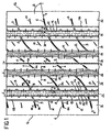
- Fig. 1 is a plan view showing a portion of the tread band of a tyre in accordance with the invention;
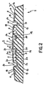
- Fig. 2 is a sectional view of the tread band taken along line II-II in Fig. 1;
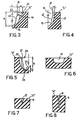
- Fig. 3 shows a fragmentary sectional view to an enlarged scale relative to the preceding figures, taken along line III-III in Fig. 1;
- Fig. 4 shows a fragmentary sectional view on an enlarged scale taken along line IV-IV in Fig. 1;
- Fig. 5 is an enlarged and fragmentary sectional view taken along line V-V in Fig. 1;
- Fig. 6 is a sectional view taken along line VI-VI in Fig. 1, still to an enlarged scale;
- Fig. 7 is an enlarged fragmentary sectional view taken along line VII-VII in Fig. 1;
- Fig. 8 is an enlarged and fragmentary sectional view taken along line VIII-VIII in Fig. 1;
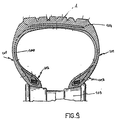
- Fig. 9 shows the section of a tyre provided with a tread band in accordance with the present invention.
- To the ends of the present description, by groove having an undulated course it is intended any groove that does not extend straight, a groove having a sinusoidal or zigzag extension, for example.
- The particular example embodying the invention, as hereinafter described, refers to a tyre having size 315/80 R 22.5 to which all punctual values of the cited critical quantities refer, whereas the variability ranges of said quantities generally refer to the wide variety of tyre sizes for medium/heavy duty.
- It is pointed out that all values cited in the progress of the present description are intended measured on a new tyre, mounted on the prescribed rim, inflated to the rated operating pressure but not loaded.
- It is also to note that tyres to which the invention is referred are usual tyres of the traditional type, commonly known to those skilled in the art, depicted in right section in the accompanying Fig. 9: they comprise a
carcass 100, of toroidal conformation, having a pair of axially-opposite sidewalls 101, terminating withbeads 102 intended for the anchoring of the tyre to acorresponding mounting rim 103, and a tread band 1 intended for the rolling contact of the tyre on the ground, disposed crownwise to said carcass, provided with a raised pattern defined by cuts and grooves formed in the thickness of said band, in this case in accordance with the present invention. - If the carcass is of the radial type, the tyres also comprise a
belt structure 104 disposed crown-wise to the carcass, interposed between the carcass and tread band, substantially extending from one tyre sidewall to the other tyre sidewall, that is as wide as the tread band. - With reference to the drawings, a tread band for tyres, in particular for lorries and the like, in accordance with the present invention has been generally identified by reference numeral 1.
- The tread band 1 has a plurality of
longitudinal grooves 2a, 2b, disposed symmetrically to the equatorial plane X-X of the tyre to which the tread band itself is applied in a raw state, before vulcanization, or already pre-moulded as in the case of covering a worn tyre by the well-known "cold" process. - The presence of the
circumferential grooves 2a, 2b defines a plurality ofcircumferential land portions 3a, 3b, 3c on the tread band 1. In more detail, in a preferential solution the presence of two circumferential central grooves 2a and twocircumferential shoulder grooves 2b is provided. - On the tread band 1 are accordingly defined a circumferential central land portion 3a, confined between the two central grooves 2a, a pair of circumferential shoulder land portions 3c extending at the side edges 1a of the tread band 1 and a pair of circumferential
intermediate land portions 3b each confined between one of the central grooves 2a and one of theshoulder grooves 2b. - Preferably, each of the central grooves 2a and
shoulder grooves 2b has a maximum width "L" included between 9 and 18 mm, preferably equal to 13 mm as regards thecentral grooves 2a and 14 mm as regards theshoulder grooves 2b, and a depth "H" included between 10 and 18 mm, preferably equal to 13.5 mm for both central 2a andshoulder 2b grooves. - In addition, the tread band 1 is provided with a plurality of transverse cuts of reduced width, usually referred to as "narrow cuts" 4, 5, 6, extending transversely in the
circumferential land portions 3a, 3b, 3c. - In accordance with a preferential feature of the present invention, the longitudinal extension of each of the
narrow cuts circumferential land portion 3a, 3b, 3c for an amount of lower width than the overall width of the land portion itself. - In other words, each
narrow cut respective ends respective land portion 3a, 3b, 3c, without opening into the adjacentcircumferential grooves 2a, 2b. - This expedient is advantageous for the tyre to reach a good steering property and therefore guide precision, and also for resistance to tearing and, more generally, for an even wear of the tread band.
- For further emphasizing these advantageous aspects the
narrow cuts - Still in Fig. 1, it can be easily noticed that, in accordance with a further preferential feature of the invention, the
narrow cuts circumferential land portions 3a, 3b, 3c are respectively disposed following a substantially undulated trend, preferably symmetrically to the equatorial plane X-X. In other words, thenarrow cuts - As clearly shown in Fig. 1,
transverse depressions - As shown in Fig. 1, the transverse depressions may extend beyond the
ends circumferential grooves 2a, 2b. - This situation is exemplified in Fig. 1, with reference to
transverse depressions - In a preferential embodiment, the circumferential central land portion 3a is provided with two series of central narrow cuts 4, located on opposite sides relative to the equatorial plane X-X, each of which has a longitudinal extension preferably included between 5 and 25 mm, more preferably of 10 mm, and a depth included between 3 and 12 mm, more preferably of 5 mm.
- The geometrical and size features of each of the
narrow cuts 6 located on the circumferential shoulder land portions 3c can be substantially identical with those of the central narrow cuts 4. - In a different embodiment the central narrow cuts 4 can extend beyond the ends 4a until they open into the adjacent circumferential grooves 2a and/or into a circumferential hollow 2, preferably disposed at the equatorial plane and preferably having a width and depth included between 1 and 5 mm and/or substantially equal to that of the
transverse depressions - The circumferential
intermediate land portions 3b, in turn, have intermediatenarrow cuts 5, each of which terminates with itsends 5a at a distance included between 1 and 6 mm, preferably of 3.5 mm, from the adjacent edge of thecircumferential groove 2a, 2b. Each intermediatenarrow cut 5 further has a maximum depth included between 6 and 16 mm, preferably of 12 mm, and is advantageously provided with a raisedcentral portion 5b (Fig. 2). Close to thiscentral portion 5b, the depth of the intermediatenarrow cut 5 is included between 1/3 and 2/3, preferably corresponding to about 1/2 of the depth detectable at theadjacent side portions 5c of the narrow cut itself. - Advantageously, the presence of the raised
portions 5b in the centralnarrow cuts 5 prevents the opposite longitudinal edges of the correspondingtransverse depression 8 and/or of the narrow cut itself from opening out too much, thereby incorporating small stones or giving rise to initiation of uneven wear. - Advantageously, the intermediate
narrow cuts 5, as well as the shouldernarrow cuts 6, can be alternated with auxiliary intermediatenarrow cuts 10 and shouldernarrow cuts 11 respectively, the geometrical and dimensional features of which may substantially correspond to those described with reference to the central 4 andshoulder 6 narrow cuts. - As clearly viewed from Figs. 2, 3 and 4, it is provided that one or more of the
circumferential grooves 2a, 2b and more specifically at least theshoulder grooves 2b, should be delimited by steppedside walls 12 the cross-section outline of which substantially extends following a broken line. - In this way, the stepped
side walls 12 define in the correspondingcircumferential groove 2b at least one radially inner portion, denoted by 13 in Figs. 3 and 4, and one radiallyouter portion 14 the width "L" of which corresponding to the maximum width of the groove itself, is greater than the width "1" of the radiallyinner portion 13. At the transition area between the radiallyinner portion 13 and the radiallyouter portion 14, the cross-sectional outline of each of theside walls 12 defines astep 15 projecting inwardly of the groove itself. Thisstep 15 is preferably oriented parallelly to the outer rolling surface of the tread band. - The presence of the
steps 15, preferably spaced apart from the outer rolling surface "S" by a distance included between 1 and 5 mm, more preferably of 3 mm, enables possible phenomena of uneven wear that may initiate along the opposite side edges of theshoulder grooves 2b to be halted. - Actually, due to the geometrical configuration of the stepped
walls 12, when the tread band is worn out as much as about 3 mm in thickness, a possible initiation of uneven wear along the edges of theshoulder grooves 2b is opposed by the emerging ofsteps 15 projecting inwardly of the groove preferably by a value m' substantially equal to 2 mm and in any case included between 1 and 4 mm. - In accordance with a further preferential feature of the present invention, each of the stepped
side walls 12 has circumferentially-distributedauxiliary cuts - In particular, provision is made for first
auxiliary cuts 16 opening onto the outer rolling surface "S" of the tread band. These firstauxiliary cuts 16 preferably have a transverse length "m" substantially corresponding to 3 mm, and extend following an outline parallel to the outline of the corresponding stepped side wall, as clearly shown in Fig. 3. - Each stepped
side wall 12 also has secondauxiliary cuts 17 penetrating the wall itself exclusively at the radiallyinner portion 13 of thegroove 2b, by a transverse length "m"' substantially corresponding to thestep 15 width. - The presence of the
auxiliary cuts 17 reveals to be advantageous for the purpose of reducing initiation of uneven-wear phenomena along the edges of the corresponding grooves 1b. - Advantageously, the second auxiliary cuts are suitable for performing their function concurrently with emerging of
steps 15 on the partly worn tread band surface, so as to offer a further hindrance to progressing of possible uneven-wear phenomena. - As viewed from Fig. 1, the first and second
auxiliary cuts grooves 2b have a series of notches k along their longitudinal extension, the notches of one edge being circumferentially graded down with those of the faced edge; every two successive notches, the edge preferably has a pair ofauxiliary cuts 17 and one auxiliary cut 16 interposed between said pair. - Third
auxiliary cuts 22 are circumferentially distributed along the opposite edges of each of the central grooves 2a. - Still for the purpose of reducing possible uneven-wear phenomena as much as possible, along the opposite side edges of one or more of the
circumferential grooves 2a, 2b, along theshoulder grooves 2b in the embodiment herein shown, provision may be advantageously made for auxiliarycircumferential hollows 18 preferably having a width and depth included between 1 and 5 mm and/or substantially equal to that of thetransverse cuts - Preferably the auxiliary circumferential hollows are arranged spaced apart from the edge of the axially adjacent groove by a distance included between 4 and 10 mm, more preferably of about 7 mm.
- Yet according to the present invention, one or more of the
circumferential grooves 2a, 2b has abottom surface 19 provided with acentral projection 20 extending longitudinally in the circumferential groove itself. Thecentral projection 20 preferably has a height "h" included between 2 and 7 mm, preferably of 3 mm, and it prevents small stones possibly captured in the groove 2a from damaging the bottom of the groove itself and/or penetrating into the tread band 1 thereby damaging the underlying belt structures. - Since the applicant has found that the possibility of stones to be entrapped is higher in the central areas of the tread, in the preferential embodiment shown the presence of central projections is provided in the central grooves 2a alone.
- For the purpose of keeping a good adhesion, even on a wet road surface as well, it is advantageously provided that, as the tyre wear increases, the
bottom surface 19 of one or more of thecircumferential grooves 2a, 2b, both central grooves 2a in the example herein shown, should extend following an undulated trend along the longitudinal extension of the groove itself.Side walls 21, having undulated trend too in the longitudinal extension of the corresponding groove 2a, connect thebottom surface 19 with the upper groove edges of the groove itself preferably having a circumferential extension. Therefore, when a tyre is new, the central grooves 2a will have a quite straight extension on the ground-contacting area. As the tyre wear goes on, extension of the central grooves 2a at the ground-contacting area will take an increasingly more marked undulation, so as to compensate for the tread band 1 wear with increasing roadholding, above all in connection with tangential forces generated on braking. - From repeated tests carried out by the applicant it has been found that the tyres of the invention efficiently solve the problem of achieving a low rolling resistance, good evenness in wear and high output per kilometre, while at the same time keeping the other performances to the highest level, particularly in terms of steering behaviour and roadholding both on a dry and a wet road.
Claims (24)
- A tyre for vehicle wheels, in particular for lorries and the like, comprising a carcass of toroidal conformation, having a pair of axially opposite sidewalls terminating with beads intended for anchoring of the tyre to a corresponding mounting rim and a tread band for rolling contact of the tyre on the ground, disposed crown-wise to said carcass and provided with a raised pattern formed in the tread thickness, comprising :a plurality of circumferential grooves (2a, 2b), disposed symmetrically to an equatorial plane (X-X) of the tyre, and defining respective circumferential land portions (3a, 3b, 3c); anda plurality of narrow cuts (4, 5, 6) transversely extending in the circumferential land portions (3a, 3b, 3c), each of said narrow cuts (4, 5, 6) having its respective ends (4a, 5a, 6a) spaced apart from the side edges of the respective circumferential land portion (3a, 3b, 3c) and having a progressively increasing inclination relative to the circumferential-extension direction parallel to the equatorial plane (X-X), on moving away from the equatorial plane itself characterized in that: at least one of said circumferential grooves (2a, 2b) has a bottom surface (19) provided with a central projection (20) extending longitudinally in the circumferential groove itself.
- A tyre according to claim 1, characterized in that at least one of said circumferential grooves (2b) is confined by stepped side walls (12) the cross-section outline of which substantially extends along a broken line to define, in the respective circumferential groove (2b), at least one radially inner portion (13) and one radially outer portion (14) of greater width (L) than the width (1) of the radially inner portion (13).
- A tyre according to claim 1, characterized in that the inclination of said narrow cuts (4, 5, 6) is included between 20 and 60° at the equatorial plane (X-X).
- A tyre according to claim 1, characterized in that the inclination of said narrow cuts (4, 5, 6) is included between 60° and 90° at the side edges of the tread band.
- A tyre according to claim 1, characterized in that each narrow cut (4, 5, 6) is substantially such arranged relative to the narrow cuts of the adjacent circumferential land portions (3a, 3b, 3c) that a substantially wavelike line is defined, as a whole, on the transverse extension of the tread band (1).
- A tyre according to claim 2, characterized in that the cross-section outline of each of said side walls (12) defines a step (15) projecting inwardly of the groove at the transition area between the radially inner portion (13) and radially outer portion (14) thereof.
- A tyre according to claim 6, characterized in that each of said steps (15) is spaced apart from the outer rolling surface (S) of the tread band (1), by an amount included between 1 and 5 mm.
- A tyre according to claim 6, characterized in that each of said steps projects inwardly of the respective circumferential groove (2b) by an amount (m') included between 1 and 4 mm.
- A tyre according to claim 1, characterized in that at least one of said circumferential grooves (2a, 2b) is confined by side walls (12, 21) having circumferentially-distributed auxiliary cuts (16, 17, 22), extending in the adjacent circumferential land portions (3a, 3b, 3c) the transverse length of which, measured perpendicularly to the equatorial plane (X-X), is included between 1 and 5 mm.
- A tyre according to claim 6, characterized in that each of said stepped side walls has first auxiliary cuts (16) opening onto the outer rolling surface (S) of the tread band (1), and second auxiliary cuts (17) the transverse length of which substantially corresponds to the width of said step (15).
- A tyre according to claim 10, characterized in that the first and second auxiliary cuts (16, 17) are intercalated following an alternated sequence.
- A tyre according to claim 1, characterized in that at least one of said narrow cuts (5) has a raised central portion (5b) on its longitudinal extension, which is interposed between two side portions (5c) of greater depth.
- A tyre according to claim 12, characterized in that at said raised central portion (5b) the narrow cut (5) has a depth included between 1/3 and 2/3 of the depth measured on the side portions (5c) of the narrow cut itself.
- A tyre according to claim 1, characterized in that at least one of said circumferential grooves (2a, 2b) has upper edges of straight extension and a bottom surface (19) extending in an undulated trend along the longitudinal extension of the groove itself.
- A tyre according to claim 1, characterized by further comprising auxiliary circumferential hollows (18) formed close to the opposite side edges of at least one of said circumferential grooves (2a, 2b).
- A tyre according to claim 15, characterized in that said circumferential hollows (18) have a width included between 1 and 5 mm and a depth included between 1 and 5 mm.
- A tyre according to claim 1, characterized by comprising two central grooves (2a) and two shoulder grooves (2b) defining a central land portion (3a) disposed symmetrically to the equatorial plane (X-X), two shoulder land portions (3c) disposed at the opposite side edges (1a) of the tread band (1) and two intermediate land portions (3b) each interposed between the central land portion (3a) and the respective shoulder land portion (3c).
- A tyre according to claim 17, characterized in that said stepped walls (12) are arranged at least on the shoulder grooves (2b).
- A tyre according to claim 1, characterized in that said central projection (20) is arranged at least in the circumferential central grooves (2a).
- A tyre according to claim 14, characterized in that said bottom surface (19) of undulated trend is arranged at least on the circumferential central grooves (2a).
- A tyre according to claim 15, characterized in that said circumferential hollows (18) are associated with at least the opposite side edges of the circumferential shoulder grooves (2b).
- A tread band, in particular for re-capping worn tyres, especially tyres for lorries and the like, pre-moulded with a raised pattern, comprising;a plurality of circumferential grooves (2a, 2b) disposed symmetrically to an equatorial plane (X-X) of the tyre and defining respective circumferential land portions (3a, 3b, 3c); anda plurality of narrow cuts (4, 5, 6) transversely extending in the circumferential land portions (3a, 3b, 3c), each of said narrow cuts (4, 5, 6) having its respective ends (4a, 5a, 6a) spaced apart from the side edges of the respective circumferential land portion (3a, 3b, 3c), said narrow cuts (4, 5, 6) having a progressively increasing inclination relative to the circumferential-extension direction parallel to the equatorial plane (X-X), on moving away from the equatorial plane itself characterized in that at least one of said circumferential grooves (2a, 2b) has a bottom surface (19) provided with a central projection (20) extending longitudinally in the circumferential groove itself.
- A tread band, according to claim 22, characterized in that - at least one of said circumferential grooves (2b) is confined by stepped side walls (12) the cross-section outline of which substantially extends following a broken line in order to define, in the respective circumferential groove (2b), - at least one radially inner portion (13) and one radially outer portion (14) having greater width (L) than the width (1) of the radially inner portion (13).
- A tread band according to claim 22, characterized in that at least one of said circumferential grooves (2a) has upper edges of straight extension and a bottom surface (19) extending in an undulated trend along the longitudinal extension of the groove itself.
Applications Claiming Priority (2)
| Application Number | Priority Date | Filing Date | Title |
|---|---|---|---|
| ITMI970150 | 1997-01-28 | ||
| IT97MI000150A IT1288435B1 (en) | 1997-01-28 | 1997-01-28 | TIRE AND TREAD BAND FOR TIRES PARTICULARLY FOR TRUCKS AND SIMILAR |
Publications (2)
| Publication Number | Publication Date |
|---|---|
| EP0855292A1 EP0855292A1 (en) | 1998-07-29 |
| EP0855292B1 true EP0855292B1 (en) | 2002-11-13 |
Family
ID=11375757
Family Applications (1)
| Application Number | Title | Priority Date | Filing Date |
|---|---|---|---|
| EP98101268A Expired - Lifetime EP0855292B1 (en) | 1997-01-28 | 1998-01-26 | Tyre and tread band for tyres, in particular for lorries and the like |
Country Status (8)
| Country | Link |
|---|---|
| EP (1) | EP0855292B1 (en) |
| JP (1) | JPH10211805A (en) |
| AR (1) | AR011778A1 (en) |
| AT (1) | ATE227655T1 (en) |
| BR (1) | BR9800497A (en) |
| DE (1) | DE69809305T2 (en) |
| ES (1) | ES2187838T3 (en) |
| IT (1) | IT1288435B1 (en) |
Cited By (1)
| Publication number | Priority date | Publication date | Assignee | Title |
|---|---|---|---|---|
| US10933697B2 (en) * | 2015-07-27 | 2021-03-02 | The Yokohama Rubber Co., Ltd. | Pneumatic tire |
Families Citing this family (31)
| Publication number | Priority date | Publication date | Assignee | Title |
|---|---|---|---|---|
| US5957180A (en) * | 1996-03-05 | 1999-09-28 | The Yokohama Rubber Co., Ltd. | Pneumatic tire including kerfs |
| JP4267735B2 (en) * | 1998-12-14 | 2009-05-27 | 株式会社ブリヂストン | Pneumatic tire |
| JP4518657B2 (en) * | 2000-09-28 | 2010-08-04 | 株式会社ブリヂストン | Pneumatic tires for left-hand traffic vehicles and pneumatic tires for right-hand traffic vehicles |
| JP4707861B2 (en) * | 2001-04-02 | 2011-06-22 | 株式会社ブリヂストン | Heavy duty tire |
| JP4530407B2 (en) * | 2004-07-20 | 2010-08-25 | 東洋ゴム工業株式会社 | Pneumatic tire |
| KR100622592B1 (en) | 2004-11-17 | 2006-09-19 | 한국타이어 주식회사 | Heavy Duty Pneumatic Tire |
| JP4586537B2 (en) * | 2004-12-28 | 2010-11-24 | 横浜ゴム株式会社 | Pneumatic tire |
| US8820373B2 (en) * | 2005-12-30 | 2014-09-02 | Continental Reifen Deutschland Gmbh | Tire having ribs, circumferential grooves and sipe pairs |
| JP4189009B2 (en) * | 2007-03-15 | 2008-12-03 | 横浜ゴム株式会社 | Pneumatic tire |
| DE102007022351A1 (en) * | 2007-05-12 | 2008-11-13 | Continental Aktiengesellschaft | Vehicle tires |
| JP4488055B2 (en) | 2007-11-02 | 2010-06-23 | 横浜ゴム株式会社 | Pneumatic tire |
| JP5160870B2 (en) | 2007-12-10 | 2013-03-13 | 東洋ゴム工業株式会社 | Pneumatic tire |
| JP2010105591A (en) * | 2008-10-31 | 2010-05-13 | Bridgestone Corp | Pneumatic tire |
| JP5210334B2 (en) * | 2010-02-05 | 2013-06-12 | 住友ゴム工業株式会社 | Heavy duty tire |
| JP5366852B2 (en) * | 2010-02-09 | 2013-12-11 | 株式会社ブリヂストン | tire |
| DE102011001295A1 (en) * | 2011-03-15 | 2012-09-20 | Continental Reifen Deutschland Gmbh | Vehicle tires |
| JP5994527B2 (en) * | 2012-09-25 | 2016-09-21 | 横浜ゴム株式会社 | Heavy duty pneumatic tire |
| CN105324253B (en) * | 2013-07-05 | 2018-08-28 | 住友橡胶工业株式会社 | Pneumatic tire |
| JP2017024662A (en) * | 2015-07-27 | 2017-02-02 | 横浜ゴム株式会社 | Pneumatic tire |
| JP6790496B2 (en) * | 2016-06-24 | 2020-11-25 | 住友ゴム工業株式会社 | Pneumatic tires |
| US10814675B2 (en) * | 2016-07-12 | 2020-10-27 | Sumitomo Rubber Industries, Ltd. | Tire |
| JP6888366B2 (en) * | 2016-07-12 | 2021-06-16 | 住友ゴム工業株式会社 | tire |
| JP6759929B2 (en) * | 2016-09-26 | 2020-09-23 | 住友ゴム工業株式会社 | Pneumatic tires |
| JP6790663B2 (en) * | 2016-09-26 | 2020-11-25 | 住友ゴム工業株式会社 | tire |
| EP3323639B1 (en) * | 2016-11-17 | 2020-05-06 | Aeolus Tyre Co., Ltd. | Tire tread |
| JP6819251B2 (en) * | 2016-12-02 | 2021-01-27 | 住友ゴム工業株式会社 | tire |
| JP6844377B2 (en) * | 2017-03-30 | 2021-03-17 | 住友ゴム工業株式会社 | tire |
| JP2019131081A (en) * | 2018-01-31 | 2019-08-08 | Toyo Tire株式会社 | Pneumatic tire |
| DE102018218084A1 (en) * | 2018-10-23 | 2020-04-23 | Continental Reifen Deutschland Gmbh | Pneumatic vehicle tires |
| JP7121695B2 (en) * | 2019-06-19 | 2022-08-18 | 株式会社ブリヂストン | tire |
| JP7629727B2 (en) * | 2020-12-23 | 2025-02-14 | Toyo Tire株式会社 | Pneumatic tires |
Family Cites Families (28)
| Publication number | Priority date | Publication date | Assignee | Title |
|---|---|---|---|---|
| DE1480889A1 (en) * | 1960-02-11 | 1969-02-06 | Continental Gummi Werke Ag | Vehicle tires, in particular pneumatic tires |
| GB1101135A (en) * | 1964-04-21 | 1968-01-31 | Dunlop Co Ltd | Improvements in or relating to pneumatic tyres |
| CA1198043A (en) * | 1981-06-12 | 1985-12-17 | Barry W. Treves | Tyre treads |
| DE3202803A1 (en) * | 1982-01-28 | 1983-08-18 | Continental Gummi-Werke Ag, 3000 Hannover | Tread design for pneumatic vehicle tyres |
| US4484610A (en) * | 1982-09-17 | 1984-11-27 | The Firestone Tire & Rubber Company | Heavy duty pneumatic tire tread |
| JPS6068803U (en) * | 1983-10-19 | 1985-05-16 | 住友ゴム工業株式会社 | Heavy load tires |
| JPS6192902A (en) * | 1984-10-13 | 1986-05-10 | Sumitomo Rubber Ind Ltd | Pneumatic radial tyre for heavy loading |
| US4854358A (en) * | 1985-06-26 | 1989-08-08 | Sumitomo Rubber Industries, Ltd. | Tread pattern for a heavy load pneumatic tire which changes from a block pattern to a rib pattern with wear |
| ES2011773B3 (en) * | 1985-10-16 | 1990-02-16 | British Telecomm | WAVE LENGTH SELECTOR |
| ZA868894B (en) * | 1985-11-30 | 1987-07-29 | Sumitomo Rubber Ind | Heavy duty pneumatic tire |
| JPH07115571B2 (en) * | 1986-04-22 | 1995-12-13 | 横浜ゴム株式会社 | Pneumatic radial tires for heavy loads |
| JPS62196705U (en) * | 1986-06-06 | 1987-12-14 | ||
| JPS63134313A (en) * | 1986-11-25 | 1988-06-06 | Yokohama Rubber Co Ltd:The | Pnermatic radial tire |
| US4936363A (en) * | 1988-08-15 | 1990-06-26 | The Goodyear Tire & Rubber Company | Tread for a pneumatic tire with circumferential slot to prevent the spread of river wear |
| JPH03132403A (en) * | 1989-10-18 | 1991-06-05 | Bridgestone Corp | Radial tire for heavy load |
| US5154216A (en) * | 1990-01-05 | 1992-10-13 | Sumitomo Rubber Industries, Ltd. | Radial tire for heavy duty vehicles |
| JPH03253408A (en) * | 1990-03-01 | 1991-11-12 | Toyo Tire & Rubber Co Ltd | Pneumatic radial tire |
| JPH0487808A (en) * | 1990-08-01 | 1992-03-19 | Bridgestone Corp | Pneumatic tire for heavy load |
| JP3076089B2 (en) * | 1991-06-25 | 2000-08-14 | 株式会社ブリヂストン | Heavy duty pneumatic tires |
| JPH05278414A (en) * | 1992-03-30 | 1993-10-26 | Bridgestone Corp | Pneumatic tire |
| JP3095301B2 (en) * | 1992-11-09 | 2000-10-03 | 東洋ゴム工業株式会社 | Radial tires for heavy loads |
| JP3193169B2 (en) * | 1992-12-22 | 2001-07-30 | 住友ゴム工業株式会社 | Pneumatic tires for heavy vehicles |
| DE4302364A1 (en) * | 1993-01-28 | 1994-08-04 | Continental Ag | Vehicle tires |
| JPH06344727A (en) * | 1993-06-04 | 1994-12-20 | Bridgestone Corp | Pneumatic tire for heavy load |
| JP2763066B2 (en) * | 1993-12-29 | 1998-06-11 | 住友ゴム工業株式会社 | Pneumatic tire |
| JPH08142610A (en) * | 1994-11-22 | 1996-06-04 | Bridgestone Corp | Pneumatic radial tire for heavy load |
| JPH08150812A (en) * | 1994-11-30 | 1996-06-11 | Bridgestone Corp | Pneumatic tire |
| JPH0911708A (en) * | 1995-06-27 | 1997-01-14 | Yokohama Rubber Co Ltd:The | Pneumatic tire |
-
1997
- 1997-01-28 IT IT97MI000150A patent/IT1288435B1/en active IP Right Grant
-
1998
- 1998-01-26 EP EP98101268A patent/EP0855292B1/en not_active Expired - Lifetime
- 1998-01-26 DE DE69809305T patent/DE69809305T2/en not_active Expired - Fee Related
- 1998-01-26 AT AT98101268T patent/ATE227655T1/en not_active IP Right Cessation
- 1998-01-26 ES ES98101268T patent/ES2187838T3/en not_active Expired - Lifetime
- 1998-01-28 JP JP10015855A patent/JPH10211805A/en active Pending
- 1998-01-28 AR ARP980100366A patent/AR011778A1/en active IP Right Grant
- 1998-01-28 BR BR9800497A patent/BR9800497A/en not_active IP Right Cessation
Cited By (1)
| Publication number | Priority date | Publication date | Assignee | Title |
|---|---|---|---|---|
| US10933697B2 (en) * | 2015-07-27 | 2021-03-02 | The Yokohama Rubber Co., Ltd. | Pneumatic tire |
Also Published As
| Publication number | Publication date |
|---|---|
| ATE227655T1 (en) | 2002-11-15 |
| ES2187838T3 (en) | 2003-06-16 |
| EP0855292A1 (en) | 1998-07-29 |
| JPH10211805A (en) | 1998-08-11 |
| DE69809305T2 (en) | 2003-07-24 |
| AR011778A1 (en) | 2000-09-13 |
| BR9800497A (en) | 1999-06-01 |
| DE69809305D1 (en) | 2002-12-19 |
| ITMI970150A1 (en) | 1998-07-28 |
| IT1288435B1 (en) | 1998-09-22 |
Similar Documents
| Publication | Publication Date | Title |
|---|---|---|
| EP0855292A1 (en) | Tyre and tread band for tyres, in particular for lorries and the like | |
| EP0841199B1 (en) | Pneumatic tyre | |
| EP0428472B1 (en) | Asymmetric tire | |
| EP1473176B1 (en) | Pneumatic tire for motorcycle | |
| EP2196332B1 (en) | Pneumatic tire | |
| US5198047A (en) | Winter type tire tread | |
| EP0904960B1 (en) | Studless tyre | |
| EP2570271B1 (en) | High mileage tire tread | |
| EP1124698B1 (en) | Tyre and tread thereof | |
| US4977942A (en) | Pneumatic tire having defined lug groove configuration | |
| JP7577569B2 (en) | Pneumatic tires | |
| EP0912355B1 (en) | A convertible tread for a radial truck or trailer tire | |
| EP3820719B1 (en) | Tyre for vehicle wheels | |
| US20030094227A1 (en) | Tyre for vehicle wheels, particularly for heavy duty vehicles such as lorries and the like | |
| JP7577570B2 (en) | Pneumatic tires | |
| EP4480718A1 (en) | Tire tread with circumferential tread groove | |
| EP2265450B1 (en) | Heavy- load vehicle tire | |
| EP1021306B1 (en) | Tread for a pneumatic tire | |
| EP0778162B1 (en) | Pneumatic tyre | |
| CA2084741C (en) | Block pattern tire with optimized groove depth ratios, sipe depth and length ratios | |
| EP1233871B1 (en) | Tyre for vehicle wheels, particularly for heavy duty vehicles such as lorries and the like | |
| JP3002402B2 (en) | Pneumatic tire | |
| US20260097611A1 (en) | Vehicle wheel tyre | |
| JP2004066837A (en) | Pneumatic tire |
Legal Events
| Date | Code | Title | Description |
|---|---|---|---|
| PUAI | Public reference made under article 153(3) epc to a published international application that has entered the european phase |
Free format text: ORIGINAL CODE: 0009012 |
|
| AK | Designated contracting states |
Kind code of ref document: A1 Designated state(s): AT DE ES FR GB IT SE |
|
| AX | Request for extension of the european patent |
Free format text: AL;LT;LV;MK;RO;SI |
|
| RAP1 | Party data changed (applicant data changed or rights of an application transferred) |
Owner name: PIRELLI PNEUMATICI SOCIETA PER AZIONI |
|
| 17P | Request for examination filed |
Effective date: 19990118 |
|
| AKX | Designation fees paid |
Free format text: AT DE ES FR GB IT SE |
|
| RBV | Designated contracting states (corrected) |
Designated state(s): AT DE ES FR GB IT SE |
|
| 17Q | First examination report despatched |
Effective date: 20000814 |
|
| GRAG | Despatch of communication of intention to grant |
Free format text: ORIGINAL CODE: EPIDOS AGRA |
|
| GRAG | Despatch of communication of intention to grant |
Free format text: ORIGINAL CODE: EPIDOS AGRA |
|
| GRAH | Despatch of communication of intention to grant a patent |
Free format text: ORIGINAL CODE: EPIDOS IGRA |
|
| GRAH | Despatch of communication of intention to grant a patent |
Free format text: ORIGINAL CODE: EPIDOS IGRA |
|
| GRAA | (expected) grant |
Free format text: ORIGINAL CODE: 0009210 |
|
| AK | Designated contracting states |
Kind code of ref document: B1 Designated state(s): AT DE ES FR GB IT SE |
|
| PG25 | Lapsed in a contracting state [announced via postgrant information from national office to epo] |
Ref country code: AT Free format text: LAPSE BECAUSE OF FAILURE TO SUBMIT A TRANSLATION OF THE DESCRIPTION OR TO PAY THE FEE WITHIN THE PRESCRIBED TIME-LIMIT Effective date: 20021113 |
|
| REF | Corresponds to: |
Ref document number: 227655 Country of ref document: AT Date of ref document: 20021115 Kind code of ref document: T |
|
| REG | Reference to a national code |
Ref country code: GB Ref legal event code: FG4D |
|
| REF | Corresponds to: |
Ref document number: 69809305 Country of ref document: DE Date of ref document: 20021219 |
|
| PG25 | Lapsed in a contracting state [announced via postgrant information from national office to epo] |
Ref country code: SE Free format text: LAPSE BECAUSE OF FAILURE TO SUBMIT A TRANSLATION OF THE DESCRIPTION OR TO PAY THE FEE WITHIN THE PRESCRIBED TIME-LIMIT Effective date: 20030213 |
|
| REG | Reference to a national code |
Ref country code: ES Ref legal event code: FG2A Ref document number: 2187838 Country of ref document: ES Kind code of ref document: T3 |
|
| ET | Fr: translation filed | ||
| PLBE | No opposition filed within time limit |
Free format text: ORIGINAL CODE: 0009261 |
|
| STAA | Information on the status of an ep patent application or granted ep patent |
Free format text: STATUS: NO OPPOSITION FILED WITHIN TIME LIMIT |
|
| 26N | No opposition filed |
Effective date: 20030814 |
|
| PGFP | Annual fee paid to national office [announced via postgrant information from national office to epo] |
Ref country code: ES Payment date: 20080128 Year of fee payment: 11 |
|
| PGFP | Annual fee paid to national office [announced via postgrant information from national office to epo] |
Ref country code: IT Payment date: 20080129 Year of fee payment: 11 Ref country code: GB Payment date: 20080129 Year of fee payment: 11 |
|
| PGFP | Annual fee paid to national office [announced via postgrant information from national office to epo] |
Ref country code: FR Payment date: 20080117 Year of fee payment: 11 Ref country code: DE Payment date: 20080229 Year of fee payment: 11 |
|
| GBPC | Gb: european patent ceased through non-payment of renewal fee |
Effective date: 20090126 |
|
| PG25 | Lapsed in a contracting state [announced via postgrant information from national office to epo] |
Ref country code: DE Free format text: LAPSE BECAUSE OF NON-PAYMENT OF DUE FEES Effective date: 20090801 |
|
| REG | Reference to a national code |
Ref country code: FR Ref legal event code: ST Effective date: 20091030 |
|
| PG25 | Lapsed in a contracting state [announced via postgrant information from national office to epo] |
Ref country code: GB Free format text: LAPSE BECAUSE OF NON-PAYMENT OF DUE FEES Effective date: 20090126 |
|
| REG | Reference to a national code |
Ref country code: ES Ref legal event code: FD2A Effective date: 20090127 |
|
| PG25 | Lapsed in a contracting state [announced via postgrant information from national office to epo] |
Ref country code: FR Free format text: LAPSE BECAUSE OF NON-PAYMENT OF DUE FEES Effective date: 20090202 Ref country code: ES Free format text: LAPSE BECAUSE OF NON-PAYMENT OF DUE FEES Effective date: 20090127 |
|
| PG25 | Lapsed in a contracting state [announced via postgrant information from national office to epo] |
Ref country code: IT Free format text: LAPSE BECAUSE OF NON-PAYMENT OF DUE FEES Effective date: 20090126 |