EP0854673B1 - Accumulator-powered lawn-mower - Google Patents
Accumulator-powered lawn-mower Download PDFInfo
- Publication number
- EP0854673B1 EP0854673B1 EP96928393A EP96928393A EP0854673B1 EP 0854673 B1 EP0854673 B1 EP 0854673B1 EP 96928393 A EP96928393 A EP 96928393A EP 96928393 A EP96928393 A EP 96928393A EP 0854673 B1 EP0854673 B1 EP 0854673B1
- Authority
- EP
- European Patent Office
- Prior art keywords
- battery
- lawnmower
- contacts
- handle
- compartment
- Prior art date
- Legal status (The legal status is an assumption and is not a legal conclusion. Google has not performed a legal analysis and makes no representation as to the accuracy of the status listed.)
- Expired - Lifetime
Links
Images

Classifications
-
- A—HUMAN NECESSITIES
- A01—AGRICULTURE; FORESTRY; ANIMAL HUSBANDRY; HUNTING; TRAPPING; FISHING
- A01D—HARVESTING; MOWING
- A01D69/00—Driving mechanisms or parts thereof for harvesters or mowers
- A01D69/02—Driving mechanisms or parts thereof for harvesters or mowers electric
Definitions
- the invention relates to a lawn mower with a electric motor powered by a rechargeable battery Drive the cutting tools with the in the preamble of the claim 1 specified characteristics.
- a lawn mower is known from WO 95/08 256.
- connection contacts formed as plug contacts between the battery and the chassis, and these plug contacts simultaneously form the mechanical locking device that holds the battery in a holder of the lawn mower chassis.
- the contact sockets fixed to the battery cover in this cover floating, i.e. laterally displaceable, stored, so too if it is not placed precisely on the pin connector in the lawn mower chassis contact can be made.
- floating storage is a mechanical fixation of the Battery in the chassis is only possible to a limited extent. Also is special safe contact cannot be guaranteed if vibrations occur, especially considering the high currents, that flow in the operation of such a lawnmower.
- the invention is therefore based on the problem of storage to improve the battery in the chassis bracket. Solved is the task set by the in the labeling part of claim 1 specified features. Through the locking bolts the battery is positively secured in the battery compartment, and even then it cannot come out of its holder fall out if the lawn mower for any reason is tipped or turned over. The locking means are coming automatically engages when the one attached to the battery housing Handle is flipped. There is also an automatic release, when the handle is raised to the battery grasp the handle and take it out so that it can be can be loaded elsewhere.
- the electrical contacting is from the mechanical fixing means completely separate. Since these contacting means according to claims 10 and 11 are designed as sliding contacts, is not a big one when removing or inserting the battery Overcoming force because the contacts are designed as sliding contacts are. On the other hand, considerable forces have to be exerted if, as in the prior art, the same time mechanically fixing plug contacts inserted into each other or must be torn apart because the plug contacts the displacement a much higher resistance oppose.
- the formation of the sliding contacts according to the invention also a self-cleaning of the contact surfaces, so that always a safe contact is guaranteed.
- the lawnmower who has the slot on his chassis for inserting the Has battery can be designed in various ways. He has an electric motor in a known manner, which by Battery 10 fed via connecting cables, not shown becomes.
- the battery 10 is an electrochemical secondary element, and this comes primarily from nickel-cadmium batteries or Lead batteries into consideration.
- the battery is in one Housing, and reference numeral 10 designates the housing built-in battery.
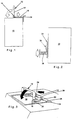
- the battery case carries a handle 12, the side legs 14 are pivotable about an axis 16.
- This bracket 18 has one or more, e.g. two, locking latch 22 on the standby of The mower engages in form-fitting recesses 24 which are in a Wall 26 of a battery well 28 are arranged, in which the Battery with housing can be used.
- the locking bolt 22 by flipping of the handle 12 inserted into the form-fitting recesses 24, whereby the battery is positively secured in the vertical direction becomes.
- the battery can the shaft removed and reinstalled in this.
- the battery 10 rests on the bottom of the shaft on elastic support means.
- These can be made of elastic material, for example be made of foam, or have springs.
- Support means from compression coil springs 30. These elastic Support means prevent abrupt placement on the Manhole bottom when the battery is moving. To ensure, that the battery is always inserted correctly in the battery compartment is, are not shown in the drawing guide means in Vertical ribs and grooves are provided. Is also one Corresponding corner design of battery housing and battery bay conceivable.
- the support means clamp the battery or its housing against the locking means in front so that the battery is in operation remains securely fixed.
- the battery or its housing For contacting, the battery or its housing carries in one Sidewall several contact tabs 32, which are in the vertical direction are provided running parallel to each other. In the battery compartment is a corresponding number of contact springs 34 arranged. These contact springs are designed as leaf springs 34 are clamped at their upper end and lie on the contact tabs 32 of the battery used under pre-tension. This preload is increased by compression springs 36 which the contact springs act and safe contacting also guarantee with the high currents flowing during operation.
- the contacting means 32, 34, 36 of the mechanical locking means 18, 22, 24 separately.
- the Sliding contact formation ensures each time it is inserted and when removing the battery self-cleaning Contacts. Even if in operation for some reason one Movement between the battery or battery housing and battery compartment takes place, so the electricity transmission not disturbed because the contacts 32 may be grinding and 34 takes place on top of each other.
- the support springs 30 can on a Carrier plate 38 act, which forms the battery compartment floor and supports the battery or its housing.
- the battery well is provided in a vertical arrangement in the lawn mower chassis.
- the shaft horizontally, the support means, the locking means and the contact means are to be designed in a corresponding manner, that a side insertion with a sliding contact connection and a side locking occurs.
Landscapes
- Life Sciences & Earth Sciences (AREA)
- Environmental Sciences (AREA)
- Harvester Elements (AREA)
- Battery Mounting, Suspending (AREA)
- Battery Electrode And Active Subsutance (AREA)
Abstract
Description
Die Erfindung bezieht sich auf einen Rasenmäher mit einem durch eine aufladbare Batterie gespeisten Elektromotor zum Antrieb der Schneidwerkzeuge mit den im Oberbegriff des Patentanspruchs 1 angegebenen Merkmalen. Ein solcher Rasenmäher ist aus der WO 95/08 256 bekannt. Hierbei sind die Verbindungskontakte zwischen Batterie und Chassis als Steckkontakte ausgebildet, und diese Steckkontakte bilden gleichzeitig die mechanischen Festlegemittel, die die Batterie in einer Halterung des Rasenmäherchassis festlegen sollen. Dabei sind die am Batteriedeckel festgelegten Kontaktbuchsen in diesem Deckel schwimmend, d.h. seitlich verschiebbar, gelagert, damit auch bei nicht zielgenauem Aufsetzen auf die Stiftstecker im Rasenmäherchassis eine Kontaktierung erfolgen kann. Infolge der schwimmenden Lagerung ist eine mechanische Festlegung der Batterie im Chassis nur begrenzt möglich. Auch ist insbesondere bei auftretenden Vibrationen eine sichere Kontaktgabe nicht gewährleistet, insbesondere wenn man die hohen Ströme berücksichtigt, die im Betrieb eines solchen Rasenmähers fließen.The invention relates to a lawn mower with a electric motor powered by a rechargeable battery Drive the cutting tools with the in the preamble of the claim 1 specified characteristics. Such a lawn mower is known from WO 95/08 256. Here are the connection contacts formed as plug contacts between the battery and the chassis, and these plug contacts simultaneously form the mechanical locking device that holds the battery in a holder of the lawn mower chassis. Here are the contact sockets fixed to the battery cover in this cover floating, i.e. laterally displaceable, stored, so too if it is not placed precisely on the pin connector in the lawn mower chassis contact can be made. As a result of floating storage is a mechanical fixation of the Battery in the chassis is only possible to a limited extent. Also is special safe contact cannot be guaranteed if vibrations occur, especially considering the high currents, that flow in the operation of such a lawnmower.
Der Erfindung liegt daher die Aufgabe zugrunde, die Lagerung der Batterie in der Chassishalterung zu verbessern. Gelöst wird die gestellte Aufgabe durch die im Kennzeichnungsteil des Patentanspruchs 1 angegebenen Merkmale. Durch die Sperrriegel wird die Batterie im Batterieschacht formschlüssig gesichert, und sie kann auch dann nicht aus ihrer Halterung herausfallen, wenn der Rasenmäher aus irgendwelchen Gründen gekippt oder umgewendet wird. Die Verriegelungsmittel kommen automatisch in Eingriff, wenn der am Batteriegehäuse ansetzende Handgriff umgelegt wird. Ebenso erfolgt eine automatische Entriegelung, wenn der Handgriff hochgeklappt wird, um die Batterie am Griff zu erfassen und herauszunehmen, damit sie an einer anderen Stelle geladen werden kann. The invention is therefore based on the problem of storage to improve the battery in the chassis bracket. Solved is the task set by the in the labeling part of claim 1 specified features. Through the locking bolts the battery is positively secured in the battery compartment, and even then it cannot come out of its holder fall out if the lawn mower for any reason is tipped or turned over. The locking means are coming automatically engages when the one attached to the battery housing Handle is flipped. There is also an automatic release, when the handle is raised to the battery grasp the handle and take it out so that it can be can be loaded elsewhere.
Die elektrische Kontaktgabe ist von den mechanischen Festlegemitteln
völlig getrennt. Da diese Kontaktierungsmittel gemäß
den Ansprüchen 10 und 11 als Schleifkontakte ausgebildet sind,
ist beim Herausnehmen oder Einführen der Batterie keine große
Kraft zu überwinden, weil die Kontakte als Schleifkontakte ausgebildet
sind. Dagegen müssen erhebliche Kräfte ausgeübt werden,
wenn, wie beim Stande der Technik, die gleichzeitig die
mechanische Festlegung bewirkenden Steckkontakte ineinandergesteckt
bzw. auseinandergerissen werden müssen, weil die Steckkontakte
der Verschiebung einen ungleich höheren Widerstand
entgegensetzen.The electrical contacting is from the mechanical fixing means
completely separate. Since these contacting means according to
Die Ausbildung der Schleifkontakte gemäß der Erfindung bewirkt auch eine Selbstreinigung der Kontaktflächen, so daß stets eine sichere Kontaktgabe gewährleistet ist.The formation of the sliding contacts according to the invention also a self-cleaning of the contact surfaces, so that always a safe contact is guaranteed.
Weitere Ausgestaltungen der Erfindung ergeben sich aus den Unteransprüchen.Further refinements of the invention result from the Subclaims.
Nachstehend wird ein Ausführungsbeispiel der Erfindung anhand
der Zeichnung beschrieben. In der Zeichnung zeigen:
In der Zeichnung sind nur die erfindungswesentlichen Teile dargestellt,
nämlich die Batterie, die Batteriehalterung und -verriegelung
sowie die Kontaktierung, während die Einzelteile des
Rasenmähers lediglich andeutungsweise angegeben sind. Der Rasenmäher,
der auf seinem Chassis den Schacht zum Einsetzen der
Batterie aufweist, kann in verschiedener Weise ausgebildet sein.
Er besitzt in bekannter Weise einen Elektromotor, der durch die
Batterie 10 über nicht dargestellte Verbindungskabel gespeist
wird. Die Batterie 10 ist ein elektrochemisches Sekundärelement,
und hierfür kommen in erster Linie Nickelcadmiumbatterien oder
Bleibatterien in Betracht. Die Batterie befindet sich in einem
Gehäuse, und das Bezugszeichen 10 bezeichnet das Gehäuse mit
eingebauter Batterie.In the drawing, only the parts essential to the invention are shown,
namely the battery, the battery holder and lock
as well as the contacting, while the individual parts of the
Lawnmower are only indicated. The lawnmower,
who has the slot on his chassis for inserting the
Has battery can be designed in various ways.
He has an electric motor in a known manner, which by
Das Batteriegehäuse trägt einen Handgriff 12, dessen Seitenschenkel
14 um eine Achse 16 schwenkbar sind. An dem unter
der Schwenkachse 16 liegenden Teil der Schenkel 14 sind die
Schenkel eines Bügels 18 um eine Achse 20 angelenkt, die unter
der Achse 16 liegt. Dieser Bügel 18 weist einen oder mehrere,
z.B. zwei, Sperriegel 22 auf, die in Bereitschaftsstellung des
Mähers in Formschlußausnehmungen 24 eingreifen, die in einer
Wand 26 eines Batterieschachtes 28 angeordnet sind, in den die
Batterie mit Gehäuse einsetzbar ist. Wie insbesondere aus den
Fig. 1 und 3 ersichtlich, werden die Sperriegel 22 durch Umlegen
des Handgriffs 12 in die Formschlußausnehmungen 24 eingeschoben,
wodurch die Batterie in vertikaler Richtung formschlüssig gesichert
wird. Nach Hochkippen des Handgriffs 12 in die aus
Fig. 1 und 2 ersichtliche Lage kann die Batterie dem Schacht
entnommen und in diesen wieder eingesetzt werden. Die Batterie
10 ruht auf dem Boden des Schachtes auf elastischen Stützmitteln.
Diese können aus elastischem Material, beispielsweise
aus Schaumstoff, ausgebildet sein oder Federn aufweisen. Gemäß
dem in Fig. 4 dargestellten Ausführungsbeispiel bestehen die
Stützmittel aus Druckschraubenfedern 30. Diese elastischen
Stützmittel verhindern ein schlagartiges Aufsetzen auf den
Schachtboden bei Bewegung der Batterie. Um zu gewährleisten,
daß die Batterie immer richtig in den Batterieschacht eingesetzt
wird, sind in der Zeichnung nicht dargestellte Führungsmittel in
Gestalt vertikaler Rippen und Nuten vorgesehen. Auch ist eine
entsprechende Eckausbildung von Batteriegehäuse und Batterieschacht
denkbar.The battery case carries a
Die Stützmittel spannen die Batterie bzw. ihr Gehäuse gegen die Verriegelungsmittel vor, so daß die Batterie im Betrieb sicher fixiert bleibt.The support means clamp the battery or its housing against the locking means in front so that the battery is in operation remains securely fixed.
Zur Kontaktierung trägt die Batterie bzw. ihr Gehäuse in einer
Seitenwand mehrere Kontaktfahnen 32, die in Vertikalrichtung
parallel zueinander verlaufend vorgesehen sind. Im Batterieschacht
ist eine entsprechende Anzahl von Kontaktfedern 34
angeordnet. Diese als Blattfedern ausgebildeten Kontaktfedern
34 sind an ihrem oberen Ende eingespannt und liegen den Kontaktfahnen
32 der eingesetzten Batterie unter Vorspannung an.
Diese Vorspannung wird durch Druckfedern 36 erhöht, die auf
die Kontaktfedern einwirken und eine sichere Kontaktgabe auch
bei den hohen im Betrieb fließenden Strömen gewährleisten.For contacting, the battery or its housing carries in one
Sidewall
Wie ersichtlich, sind die Kontaktierungsmittel 32, 34, 36 von
den mechanischen Verriegelungsmitteln 18, 22, 24 getrennt. Die
Schleifkontaktausbildung gewährleistet jeweils beim Einsetzen
und beim Herausnehmen der Batterie eine Selbstreinigung der
Kontakte. Selbst wenn im Betrieb aus irgendwelchen Gründen eine
Bewegung zwischen Batterie bzw. Batteriegehäuse und Batterieschacht
stattfindet, so wird dadurch die Stromübertragung
nicht gestört, weil allenfalls ein Schleifen der Kontakte 32
und 34 aufeinander erfolgt.As can be seen, the contacting means 32, 34, 36 of
the mechanical locking means 18, 22, 24 separately. The
Sliding contact formation ensures each time it is inserted
and when removing the battery self-cleaning
Contacts. Even if in operation for some reason one
Movement between the battery or battery housing and battery compartment
takes place, so the electricity transmission
not disturbed because the
Wie aus Fig. 5 ersichtlich, können die Stützfedern 30 auf eine
Trägerplatte 38 wirken, die den Batterieschachtboden bildet
und die Batterie bzw. deren Gehäuse abstützt.5, the
Gemäß dem dargestellten Ausführungsbeispiel ist der Batterieschacht im Rasenmäherchassis in vertikaler Anordnung vorgesehen. Es ist jedoch auch denkbar, den Schacht horizontal auszubilden, wobei die Stützmittel, die Verriegelungsmittel und die Kontaktmittel in entsprechender Weise so auszubilden sind, daß ein seitliches Einschieben mit einer Schleifkontaktverbindung und einer seitlichen Verriegelung zustandekommt. According to the illustrated embodiment, the battery well is provided in a vertical arrangement in the lawn mower chassis. However, it is also conceivable to design the shaft horizontally, the support means, the locking means and the contact means are to be designed in a corresponding manner, that a side insertion with a sliding contact connection and a side locking occurs.
- 1010th
- Batterie(gehäuse)Battery (housing)
- 1212th
- HandgriffHandle
- 1414
- SeitenschenkelSide thighs
- 1616
- Achseaxis
- 1818th
- Bügelhanger
- 2020th
- Achseaxis
- 2222
- SperriegelLocking bolt
- 2424th
- FormschlußausnehmungenForm-fit recesses
- 2626
- Wandwall
- 2828
- BatterieschachtBattery bay
- 3030th
- DruckschraubenfedernCompression coil springs
- 3232
- KontaktfahnenContact flags
- 3434
- KontaktfedernContact springs
- 3636
- DruckschraubenfedernCompression coil springs
- 3838
- TrägerplatteCarrier plate
Claims (15)
- Lawnmower with an electric motor powered by a rechargeable battery for driving the cutting tools, comprising the following features:a mounting (28) is provided for the battery (10) on the chassis;the battery is provided with a handle (12) by means of which it can be removed from the mounting and inserted thereinto;the battery incorporates electrical contacts (32) which touch and create a contact with mating contacts (34) on the drive circuit as the battery is being inserted into the mounting;the battery is secured mechanically in the mounting by locating means (22);
characterised in thatthe locating means are separate from the contact means and consist of a form-closure interlocking device;the mounting (28) incorporates form-closure rebates (24) andthe handle (12) is swivel-mounted and coupled to safety catches (22) which engage the form-closure rebates when the handle (12) is folded down and released when it is raised. - Lawnmower as claimed in claim 1,
characterised in that the mounting is configured as a well (28) which incorporates the form-closure rebates (24) in the upper portion of a wall. - Lawnmower as claimed in claim 1,
characterised in that the safety catches (22) are hinged on the side-pieces (14) of the handle, adjacent to the swivelling axis. - Lawnmower as claimed in claim 3,
characterised in that the safety catches (22) are attached to the centre arm of a bracket (18) which is hinged at the two handle side-pieces (14). - Lawnmower as claimed in claims 1 to 4,
characterised in that the safety catches (22) are positioned horizontally on the upper part of the battery. - Lawnmower as claimed in any of claims 1 to 5,
characterised in that flexible support means (30) are arranged on the floor of the battery well (28). - Lawnmower as claimed in claim 6,
characterised in that the support means (30) pretension the safety catches (22) against the rim of the form-closure rebates (24). - Lawnmower as claimed in claims 6 and 7,
characterised in that the support means are in the form of springs, e.g. pressing screw springs (30), which act directly or indirectly on the battery floor. - Lawnmower as claimed in claim 1,
characterised in that contact is made with the battery contacts independently of the locating means. - Lawnmower as claimed in claims 1 and 9,
characterised in that the battery contacts are arranged in a side wall of the battery (10) and are in the form of sliding-action contacts which cooperate with the mating contacts of the chassis which are in the form of sliding-action contacts. - Lawnmower as claimed in claim 10,
characterised in that the mating contacts are leaf springs (34) which are individually supported by pressing screw springs (36). - Lawnmower as claimed in any of claims 1 to 11,
characterised in that the battery (10) is surrounded by an enclosure which carries the handle, the locating means and the contacts. - Lawnmower as claimed in claim 1,
characterised in that the battery (10) optionally also powers a drive propulsion motor. - Lawnmower as claimed in claim 1, characterised in that associated with the battery (10) is
a charger, the contacts of which are configured in accordance with Claims 10 and 11. - Lawnmower as claimed in any of claims 1 to 14,
characterised in that the battery enclosure and the battery well (28) are equipped with mutually corresponding fit alignment surfaces.
Applications Claiming Priority (3)
| Application Number | Priority Date | Filing Date | Title |
|---|---|---|---|
| DE19528167A DE19528167C1 (en) | 1995-08-01 | 1995-08-01 | Lawn mower with battery charged electric motor |
| DE19528167 | 1995-08-01 | ||
| PCT/EP1996/003350 WO1997004638A1 (en) | 1995-08-01 | 1996-07-30 | Accumulator-powered lawn-mower |
Publications (2)
| Publication Number | Publication Date |
|---|---|
| EP0854673A1 EP0854673A1 (en) | 1998-07-29 |
| EP0854673B1 true EP0854673B1 (en) | 1999-03-24 |
Family
ID=7768365
Family Applications (1)
| Application Number | Title | Priority Date | Filing Date |
|---|---|---|---|
| EP96928393A Expired - Lifetime EP0854673B1 (en) | 1995-08-01 | 1996-07-30 | Accumulator-powered lawn-mower |
Country Status (6)
| Country | Link |
|---|---|
| US (1) | US5937623A (en) |
| EP (1) | EP0854673B1 (en) |
| AT (1) | ATE177898T1 (en) |
| DE (2) | DE19528167C1 (en) |
| ES (1) | ES2129985T3 (en) |
| WO (1) | WO1997004638A1 (en) |
Cited By (2)
| Publication number | Priority date | Publication date | Assignee | Title |
|---|---|---|---|---|
| DE102009041397A1 (en) | 2009-08-24 | 2011-03-03 | Gardena Manufacturing Gmbh | Battery operated device and battery for it |
| EP3217780B1 (en) | 2014-11-14 | 2019-09-18 | Techtronic Industries Company Limited | Electric lawn mower |
Families Citing this family (30)
| Publication number | Priority date | Publication date | Assignee | Title |
|---|---|---|---|---|
| US5819513A (en) * | 1993-09-22 | 1998-10-13 | Briggs & Stratton Corporation | Power head assembly for electric grass cutting device |
| DE19528166C1 (en) * | 1995-08-01 | 1996-08-01 | Wolf Geraete Gmbh Vertrieb | Battery driven lawn mower |
| FR2768298B1 (en) * | 1997-09-12 | 1999-11-12 | Wolf Outils | LAWNMOWER WITH ELECTRIC MOTOR |
| US7007446B2 (en) * | 2000-10-26 | 2006-03-07 | Textron Inc. | Battery-powered walk-behind greensmower |
| US8267210B2 (en) * | 2003-10-08 | 2012-09-18 | Pride Mobility Products Corporation | Power supply assembly for motorized vehicles |
| US7967095B2 (en) | 2003-10-08 | 2011-06-28 | Pride Mobility Products Corporation | Collapsible vehicle |
| US7413045B2 (en) * | 2005-11-30 | 2008-08-19 | Karma Medical Products Co., Ltd. | Battery quick-release structure for an electric mobility scooter |
| GB0615241D0 (en) | 2006-08-01 | 2006-09-06 | Bosch Gmbh Robert | Lawn-care apparatus |
| WO2008048618A2 (en) | 2006-10-17 | 2008-04-24 | Desa Ip. Llc | Hybrid electric device |
| US7728534B2 (en) | 2006-10-17 | 2010-06-01 | Mtd Products Inc | Hybrid electric lawnmower |
| US8732896B2 (en) | 2006-10-17 | 2014-05-27 | Mtd Products Inc | Hybrid electric cleaning device |
| US8076873B1 (en) | 2007-06-01 | 2011-12-13 | Mtd Products Inc | Hybrid outdoor power equipment |
| US8653786B2 (en) * | 2008-04-25 | 2014-02-18 | Black & Decker Inc. | Cordless mower including battery with two charging connectors |
| DE202009015277U1 (en) * | 2009-11-11 | 2010-04-08 | Ze-Mobility Gmbh & Co. Kg | Battery with holding device |
| CN103402710B (en) | 2011-03-03 | 2015-10-07 | 胡斯华纳有限公司 | Battery-powered tools and the battery pack for battery-powered tools |
| ITMI20111511A1 (en) * | 2011-08-08 | 2013-02-09 | Ggp Italy Spa | ELECTRICAL BATTERY CONNECTION DEVICE. |
| US8727233B2 (en) | 2011-10-17 | 2014-05-20 | Champion Power Equipment, Inc. | Pressure spray washer and control |
| US8733072B2 (en) | 2011-11-04 | 2014-05-27 | Briggs & Stratton Corporation | Starter system for an engine |
| US9127658B2 (en) | 2011-11-04 | 2015-09-08 | Briggs & Stratton Corporation | Internal combustion engine including starting system powered by lithium-ion battery |
| US8857138B2 (en) | 2011-11-04 | 2014-10-14 | Briggs & Stratton Corporation | Starter system for an engine |
| EP2636295B1 (en) * | 2012-03-07 | 2014-09-10 | Robert Bosch GmbH | Lawn-care apparatus |
| US10130962B2 (en) | 2013-10-10 | 2018-11-20 | Briggs & Stratton Corporation | Wirelessly controlled trigger start and chemical tank change-over for pressure washers |
| AU2015226967A1 (en) | 2014-03-06 | 2016-09-22 | Briggs & Stratton Corporation | Rechargeable battery system for replacement of lead-acid battery |
| US9991825B1 (en) | 2014-11-24 | 2018-06-05 | The Toro Company | Outdoor power equipment system with modular motor and modular battery |
| USD795181S1 (en) | 2016-06-15 | 2017-08-22 | Briggs & Stratton Corporation | Battery |
| JP2018092746A (en) | 2016-11-30 | 2018-06-14 | 本田技研工業株式会社 | Battery attachment structure |
| CN110381726B (en) * | 2016-11-30 | 2022-05-06 | 本田技研工业株式会社 | Electric working machine |
| CN111067423B (en) * | 2018-10-19 | 2022-07-19 | 德国福维克控股公司 | Replaceable accumulator |
| KR102204986B1 (en) * | 2019-07-09 | 2021-01-19 | 주식회사 한국아트라스비엑스 | Automotive Lead-acid batteries with fold-down hold down structure |
| DE102020206984A1 (en) | 2020-06-04 | 2021-12-09 | Robert Bosch Gesellschaft mit beschränkter Haftung | Battery, vehicle and method of making one |
Family Cites Families (20)
| Publication number | Priority date | Publication date | Assignee | Title |
|---|---|---|---|---|
| GB188355A (en) * | 1921-07-05 | 1922-11-06 | Samuel Trench | A shock proof accumulator case |
| US2909885A (en) * | 1958-05-21 | 1959-10-27 | Smith Philip | Battery powered disk type lawn mower |
| DE2210557A1 (en) * | 1972-03-04 | 1973-09-06 | Gutbrod Werke Gmbh | MOVABLE BASE PLATE AS A CHASSIS FOR THE COMMON ENERGY DISPENSER OF SEVERAL GAERTNICAL OR AGRICULTURAL WORK TOOLS |
| US3999110A (en) * | 1975-02-06 | 1976-12-21 | The Black And Decker Manufacturing Company | Battery pack and latch |
| US3973378A (en) * | 1975-03-18 | 1976-08-10 | Disston, Inc. | Cordless grass trimmer having removable battery pack |
| US4031696A (en) * | 1975-08-08 | 1977-06-28 | The Black And Decker Manufacturing Company | Blade configuration for cordless lawnmower |
| US4064680A (en) * | 1975-08-08 | 1977-12-27 | The Black And Decker Manufacturing Company | Cordless twin blade lawnmower construction |
| US4333302A (en) * | 1981-03-13 | 1982-06-08 | Ronald Thomas | Combined A.C./D.C. electric lawn mower |
| US4446680A (en) * | 1982-04-26 | 1984-05-08 | Alessandro Thomas C D | Battery powered lawn edger |
| US4508794A (en) * | 1984-01-25 | 1985-04-02 | Wright Anthony A | Security battery holder |
| ES8609823A1 (en) * | 1985-07-22 | 1986-09-01 | Tudor Acumulador | Electric accumulator battery. |
| US4847170A (en) * | 1988-09-09 | 1989-07-11 | Pulse Electronics, Inc. | Battery container and adapter |
| US4930300A (en) * | 1989-06-02 | 1990-06-05 | Deere & Company | Lawn mower battery mounting |
| US4983473A (en) * | 1989-06-16 | 1991-01-08 | Smith James L | Auxiliary power source with charger and integral light source |
| FR2661066B1 (en) * | 1990-04-18 | 1992-06-12 | Balva Brigitte | LAWN MOWER DEVICE WITH ELECTRIC MOTOR POWERED BY A BATTERY. |
| US5085043A (en) * | 1990-06-01 | 1992-02-04 | Black & Decker Inc. | Electro-mechanical interlock and module system for lawn mower or other electrical device |
| DE9313032U1 (en) * | 1993-08-31 | 1993-12-02 | Al Ko Geraete Gmbh | Mobile working device |
| AU7600894A (en) * | 1993-09-22 | 1995-04-10 | Briggs & Stratton Corporation | Battery-powered vegetation cutting system and method of using same |
| US5606851A (en) * | 1993-09-22 | 1997-03-04 | Briggs & Stratton Corporation | Battery-powered lawn cutting system |
| EP0777410A2 (en) * | 1994-08-22 | 1997-06-11 | BRIGGS & STRATTON CORPORATION | Improved battery-powered lawn cutting system |
-
1995
- 1995-08-01 DE DE19528167A patent/DE19528167C1/en not_active Expired - Fee Related
-
1996
- 1996-07-30 EP EP96928393A patent/EP0854673B1/en not_active Expired - Lifetime
- 1996-07-30 WO PCT/EP1996/003350 patent/WO1997004638A1/en active IP Right Grant
- 1996-07-30 DE DE59601521T patent/DE59601521D1/en not_active Expired - Fee Related
- 1996-07-30 AT AT96928393T patent/ATE177898T1/en not_active IP Right Cessation
- 1996-07-30 US US09/011,163 patent/US5937623A/en not_active Expired - Fee Related
- 1996-07-30 ES ES96928393T patent/ES2129985T3/en not_active Expired - Lifetime
Cited By (3)
| Publication number | Priority date | Publication date | Assignee | Title |
|---|---|---|---|---|
| DE102009041397A1 (en) | 2009-08-24 | 2011-03-03 | Gardena Manufacturing Gmbh | Battery operated device and battery for it |
| EP2299516A1 (en) | 2009-08-24 | 2011-03-23 | GARDENA Manufacturing GmbH | Battery-operated device and battery for same |
| EP3217780B1 (en) | 2014-11-14 | 2019-09-18 | Techtronic Industries Company Limited | Electric lawn mower |
Also Published As
| Publication number | Publication date |
|---|---|
| DE59601521D1 (en) | 1999-04-29 |
| ATE177898T1 (en) | 1999-04-15 |
| DE19528167C1 (en) | 1996-08-29 |
| EP0854673A1 (en) | 1998-07-29 |
| ES2129985T3 (en) | 1999-06-16 |
| WO1997004638A1 (en) | 1997-02-13 |
| US5937623A (en) | 1999-08-17 |
Similar Documents
| Publication | Publication Date | Title |
|---|---|---|
| EP0854673B1 (en) | Accumulator-powered lawn-mower | |
| EP2223779B1 (en) | Portable, hand-held electric device with a battery pack | |
| EP1620233B1 (en) | Electrical hand tool machine with an accumulator pack | |
| DE102005032210B4 (en) | Isolating device for a circuit | |
| DE69737858T2 (en) | SELF-LOCKING BATTERY FOR PORTABLE DEFIBRILLATOR | |
| EP2431134B1 (en) | Handheld tool with an electric drive motor | |
| DE602004013398T2 (en) | battery ejection mechanism | |
| DE10051754A1 (en) | Battery charger with protective device for a connection point | |
| DE19604648A1 (en) | Battery-powered grass cutting device e.g. lawnmower or shears | |
| DE102007046565A1 (en) | Power generating device such as a generator | |
| EP1794463A1 (en) | Device for locking electric appliances in particular electric tools with battery packs for power supply | |
| DE1928081U (en) | HOLDING AND CHARGING DEVICE FOR AN ELECTRIC KNIFE. | |
| EP2886006B1 (en) | Support system for modular battery unit | |
| DE112011101612B4 (en) | Safety device for high voltage components | |
| DE202017006868U1 (en) | Battery pack, electrical appliance using the battery pack and electrical appliance system | |
| EP0499838B1 (en) | Electric apparatus | |
| DE19931368A1 (en) | A circular saw table with vertically moveable saw unit for cutting workpieces held on the table in which the saw blade is driven by a battery operated DC motor | |
| DE102006042602A1 (en) | Battery pack, power tool and charger with inductive coupling | |
| DE19614199C1 (en) | Tool with a battery-operated electric motor | |
| DE3150652A1 (en) | Vehicle with an electrical drive motor | |
| EP3451888B1 (en) | Floor treatment system | |
| EP0548575B1 (en) | Holder for battery powered electric device with connection to a power source | |
| EP0841847B1 (en) | Accumulator-powered lawn mower | |
| DE102007042398A1 (en) | charger | |
| DE102022000205A1 (en) | working machine |
Legal Events
| Date | Code | Title | Description |
|---|---|---|---|
| PUAI | Public reference made under article 153(3) epc to a published international application that has entered the european phase |
Free format text: ORIGINAL CODE: 0009012 |
|
| 17P | Request for examination filed |
Effective date: 19980429 |
|
| AK | Designated contracting states |
Kind code of ref document: A1 Designated state(s): AT BE CH DE ES FR GB IT LI NL SE |
|
| GRAG | Despatch of communication of intention to grant |
Free format text: ORIGINAL CODE: EPIDOS AGRA |
|
| GRAG | Despatch of communication of intention to grant |
Free format text: ORIGINAL CODE: EPIDOS AGRA |
|
| GRAH | Despatch of communication of intention to grant a patent |
Free format text: ORIGINAL CODE: EPIDOS IGRA |
|
| 17Q | First examination report despatched |
Effective date: 19980818 |
|
| GRAH | Despatch of communication of intention to grant a patent |
Free format text: ORIGINAL CODE: EPIDOS IGRA |
|
| GRAA | (expected) grant |
Free format text: ORIGINAL CODE: 0009210 |
|
| ITF | It: translation for a ep patent filed |
Owner name: BARZANO' E ZANARDO MILANO S.P.A. |
|
| AK | Designated contracting states |
Kind code of ref document: B1 Designated state(s): AT BE CH DE ES FR GB IT LI NL SE |
|
| PG25 | Lapsed in a contracting state [announced via postgrant information from national office to epo] |
Ref country code: FR Free format text: THE PATENT HAS BEEN ANNULLED BY A DECISION OF A NATIONAL AUTHORITY Effective date: 19990324 |
|
| REF | Corresponds to: |
Ref document number: 177898 Country of ref document: AT Date of ref document: 19990415 Kind code of ref document: T |
|
| REG | Reference to a national code |
Ref country code: CH Ref legal event code: NV Representative=s name: KIRKER & CIE SA Ref country code: CH Ref legal event code: EP |
|
| ET | Fr: translation filed | ||
| GBT | Gb: translation of ep patent filed (gb section 77(6)(a)/1977) |
Effective date: 19990325 |
|
| REF | Corresponds to: |
Ref document number: 59601521 Country of ref document: DE Date of ref document: 19990429 |
|
| REG | Reference to a national code |
Ref country code: ES Ref legal event code: FG2A Ref document number: 2129985 Country of ref document: ES Kind code of ref document: T3 |
|
| PG25 | Lapsed in a contracting state [announced via postgrant information from national office to epo] |
Ref country code: ES Free format text: LAPSE BECAUSE OF NON-PAYMENT OF DUE FEES Effective date: 19990731 |
|
| PLBE | No opposition filed within time limit |
Free format text: ORIGINAL CODE: 0009261 |
|
| STAA | Information on the status of an ep patent application or granted ep patent |
Free format text: STATUS: NO OPPOSITION FILED WITHIN TIME LIMIT |
|
| 26N | No opposition filed | ||
| REG | Reference to a national code |
Ref country code: FR Ref legal event code: ST |
|
| PG25 | Lapsed in a contracting state [announced via postgrant information from national office to epo] |
Ref country code: LI Free format text: LAPSE BECAUSE OF NON-PAYMENT OF DUE FEES Effective date: 20000731 Ref country code: CH Free format text: LAPSE BECAUSE OF NON-PAYMENT OF DUE FEES Effective date: 20000731 |
|
| REG | Reference to a national code |
Ref country code: CH Ref legal event code: PL |
|
| PGFP | Annual fee paid to national office [announced via postgrant information from national office to epo] |
Ref country code: NL Payment date: 20010606 Year of fee payment: 6 |
|
| PGFP | Annual fee paid to national office [announced via postgrant information from national office to epo] |
Ref country code: DE Payment date: 20010607 Year of fee payment: 6 |
|
| PGFP | Annual fee paid to national office [announced via postgrant information from national office to epo] |
Ref country code: SE Payment date: 20010608 Year of fee payment: 6 Ref country code: AT Payment date: 20010608 Year of fee payment: 6 |
|
| PGFP | Annual fee paid to national office [announced via postgrant information from national office to epo] |
Ref country code: BE Payment date: 20010629 Year of fee payment: 6 |
|
| PGFP | Annual fee paid to national office [announced via postgrant information from national office to epo] |
Ref country code: GB Payment date: 20010718 Year of fee payment: 6 |
|
| REG | Reference to a national code |
Ref country code: GB Ref legal event code: IF02 |
|
| PG25 | Lapsed in a contracting state [announced via postgrant information from national office to epo] |
Ref country code: GB Free format text: LAPSE BECAUSE OF NON-PAYMENT OF DUE FEES Effective date: 20020730 Ref country code: AT Free format text: LAPSE BECAUSE OF NON-PAYMENT OF DUE FEES Effective date: 20020730 |
|
| PG25 | Lapsed in a contracting state [announced via postgrant information from national office to epo] |
Ref country code: SE Free format text: LAPSE BECAUSE OF NON-PAYMENT OF DUE FEES Effective date: 20020731 Ref country code: BE Free format text: LAPSE BECAUSE OF NON-PAYMENT OF DUE FEES Effective date: 20020731 |
|
| BERE | Be: lapsed |
Owner name: *WOLF-GERATE G.M.B.H. VERTRIEBSGESELLSCHAFT K.G. Effective date: 20020731 |
|
| PG25 | Lapsed in a contracting state [announced via postgrant information from national office to epo] |
Ref country code: NL Free format text: LAPSE BECAUSE OF NON-PAYMENT OF DUE FEES Effective date: 20030201 Ref country code: DE Free format text: LAPSE BECAUSE OF NON-PAYMENT OF DUE FEES Effective date: 20030201 |
|
| EUG | Se: european patent has lapsed | ||
| GBPC | Gb: european patent ceased through non-payment of renewal fee |
Effective date: 20020730 |
|
| NLV4 | Nl: lapsed or anulled due to non-payment of the annual fee |
Effective date: 20030201 |
|
| REG | Reference to a national code |
Ref country code: ES Ref legal event code: FD2A Effective date: 20000810 |
|
| PG25 | Lapsed in a contracting state [announced via postgrant information from national office to epo] |
Ref country code: IT Free format text: LAPSE BECAUSE OF NON-PAYMENT OF DUE FEES;WARNING: LAPSES OF ITALIAN PATENTS WITH EFFECTIVE DATE BEFORE 2007 MAY HAVE OCCURRED AT ANY TIME BEFORE 2007. THE CORRECT EFFECTIVE DATE MAY BE DIFFERENT FROM THE ONE RECORDED. Effective date: 20050730 |