EP0854661A2 - Microwave oven with safety system - Google Patents

Microwave oven with safety system Download PDF

Info

Publication number
EP0854661A2
EP0854661A2 EP97309544A EP97309544A EP0854661A2 EP 0854661 A2 EP0854661 A2 EP 0854661A2 EP 97309544 A EP97309544 A EP 97309544A EP 97309544 A EP97309544 A EP 97309544A EP 0854661 A2 EP0854661 A2 EP 0854661A2
Authority
EP
European Patent Office
Prior art keywords
heater
temperature
door
microwave oven
cooking chamber
Prior art date
Legal status (The legal status is an assumption and is not a legal conclusion. Google has not performed a legal analysis and makes no representation as to the accuracy of the status listed.)
Withdrawn
Application number
EP97309544A
Other languages
German (de)
French (fr)
Other versions
EP0854661A3 (en
Inventor
Gi-Hun Lee
Current Assignee (The listed assignees may be inaccurate. Google has not performed a legal analysis and makes no representation or warranty as to the accuracy of the list.)
Samsung Electronics Co Ltd
Original Assignee
Samsung Electronics Co Ltd
Priority date (The priority date is an assumption and is not a legal conclusion. Google has not performed a legal analysis and makes no representation as to the accuracy of the date listed.)
Filing date
Publication date
Application filed by Samsung Electronics Co Ltd filed Critical Samsung Electronics Co Ltd
Publication of EP0854661A2 publication Critical patent/EP0854661A2/en
Publication of EP0854661A3 publication Critical patent/EP0854661A3/en
Withdrawn legal-status Critical Current

Links

Images

Classifications

    • HELECTRICITY
    • H05ELECTRIC TECHNIQUES NOT OTHERWISE PROVIDED FOR
    • H05BELECTRIC HEATING; ELECTRIC LIGHT SOURCES NOT OTHERWISE PROVIDED FOR; CIRCUIT ARRANGEMENTS FOR ELECTRIC LIGHT SOURCES, IN GENERAL
    • H05B6/00Heating by electric, magnetic or electromagnetic fields
    • H05B6/64Heating using microwaves
    • H05B6/6447Method of operation or details of the microwave heating apparatus related to the use of detectors or sensors
    • H05B6/645Method of operation or details of the microwave heating apparatus related to the use of detectors or sensors using temperature sensors
    • HELECTRICITY
    • H05ELECTRIC TECHNIQUES NOT OTHERWISE PROVIDED FOR
    • H05BELECTRIC HEATING; ELECTRIC LIGHT SOURCES NOT OTHERWISE PROVIDED FOR; CIRCUIT ARRANGEMENTS FOR ELECTRIC LIGHT SOURCES, IN GENERAL
    • H05B6/00Heating by electric, magnetic or electromagnetic fields
    • H05B6/64Heating using microwaves
    • H05B6/6414Aspects relating to the door of the microwave heating apparatus
    • HELECTRICITY
    • H05ELECTRIC TECHNIQUES NOT OTHERWISE PROVIDED FOR
    • H05BELECTRIC HEATING; ELECTRIC LIGHT SOURCES NOT OTHERWISE PROVIDED FOR; CIRCUIT ARRANGEMENTS FOR ELECTRIC LIGHT SOURCES, IN GENERAL
    • H05B6/00Heating by electric, magnetic or electromagnetic fields
    • H05B6/64Heating using microwaves
    • H05B6/647Aspects related to microwave heating combined with other heating techniques
    • H05B6/6482Aspects related to microwave heating combined with other heating techniques combined with radiant heating, e.g. infrared heating
    • HELECTRICITY
    • H05ELECTRIC TECHNIQUES NOT OTHERWISE PROVIDED FOR
    • H05BELECTRIC HEATING; ELECTRIC LIGHT SOURCES NOT OTHERWISE PROVIDED FOR; CIRCUIT ARRANGEMENTS FOR ELECTRIC LIGHT SOURCES, IN GENERAL
    • H05B6/00Heating by electric, magnetic or electromagnetic fields
    • H05B6/64Heating using microwaves
    • H05B6/66Circuits
    • H05B6/666Safety circuits

Definitions

  • the present invention a microwave oven having a radiant heater element located in a cooking chamber and a door to the cooking chamber.
  • a microwave oven is a cooking appliance which cooks food with rf energy at 2450MHz. Water molecules in food to be cooked oscillate in sympathy with the rf field in the cooking chamber of the oven generating heat. Microwave ovens are often provided with a heating element in their cooking chambers for grilling food.
  • FIG 1 is a front view of a known microwave oven.
  • the known microwave oven includes a cooking chamber 10 in which food is cooked, a cooking chamber door 20 for providing access to the cooking chamber 10, a rotary motor (not illustrated), a rotary stand 11 connected with the rotary motor, and a tray 12 positioned on the rotary stand 11, and on which the food is placed for cooking.
  • the known microwave oven also includes a heater 13 for grilling food, a thermistor 14 which senses the temperature of the cooking chamber 10, a control panel having a display 30 showing operational information of the microwave oven and a function selection part 40, a magnetron antenna (not shown) for supplying microwave energy to the cooking chamber 10 and which is mounted to an upper portion of a sidewall of the cooking chamber 10, and a magnetron (not shown) installed in a space at the rear of the display 30 for generating microwave energy and supplying it to the magnetron antenna.
  • the heater 13 is mounted at the rear of the upper portion of the cooking chamber 10.
  • the heater 13 is rotatable and is held in place by supporting members provided on the side walls of the cooking chamber 10.
  • a cooking chamber lamp (not shown) is switched on to illuminate the cooking chamber 10, and the tray 11 rotates. Heat is produced when electricity is applied to the heater 13.
  • the electricity applied to the heater 13 is shut off, and the heater 13 stops producing heat.
  • the microwave oven informs the user.
  • the know microwave oven with the heater 13 maintains a high temperature for a predetermined period of time even after the cooking time has finished. Since the known microwave oven has no means to measure the temperature of the heater 13, which falls slowly when power is removed, a user does not know how much hotter than the air in the cooking chamber 10 the heater 13 is. Thus, when a user tries to cook food with the known microwave oven before the heater 13 cools, he may touch the hot heater 13 as he either puts food into or takes food out of the cooking chamber 10. If his or her hand touches the heater 13, he or she may get burnt and instantaneously drop the food that he or she is holding, thus making the cooking chamber 10 dirty.
  • a microwave oven according to the present invention is characterised by a temperature sensor for sensing the temperature of the heater element and alarm means responsive to opening of the door and the temperature sensor to produce an alarm signal if the temperature sensor indicates that the heater element is above a predetermined temperature when the door is being opened.
  • a switch is used for detecting opening of the door.
  • a piezoelectric element could be used instead.
  • the temperature sensor preferably comprises a bimetal temperature sensor or a thermistor. If a thermistor is being used, the temperature sensor outputs a voltage related to the surface temperature of the heater element, a control unit compares this voltage with a reference voltage corresponding to a reference temperature, and controls the generation of the alarm.
  • a microwave oven includes a heater temperature sensor 15 for checking the temperature of a heater 13, and this heater temperature sensor 15 is disposed on the cooking chamber 10's ceiling close to the heater 13.
  • a function selection part 40 and display 30 are provided at the front of the microwave oven to allow a user to control the oven and confirm its operation with ease.
  • the function selection part 40 has a cooking selection switch, a grill mode selection switch, and a power switch.
  • the display 30 shows a user the control information programmed using the function selection part 40, and includes a visual alarm 50-1 which gives a user a warning if the temperature of the heater 13 is high when he or she opens a door 20 of the microwave oven.
  • An audio alarm 50-2 such as a buzzer is provided at the bottom righthand corner of the display 30.
  • Figure 3 is a circuit diagram of the inventive safety system, including the heater temperature sensor 15 for checking the temperature of the heater 13, and visual and audio alarms 50-1 and 50-2.
  • the safety system includes a control unit 90 to which the heater temperature sensor 15 is coupled in series with a resistor R therebetween, and an alarm device 50 that is operated by an output signal of the control unit 90.
  • the control unit 90 controls the alarm device 50 according to the value of the voltage output by the heater temperature sensor 15 that checks the temperature of the heater.
  • a reference temperature for the heater temperature sensor 15 is set to 50°C.
  • the reference temperature of the heater temperature sensor 15 is set to a value that will avoid a user from getting a burn when he or she touches the heater 13.
  • the alarm device 50 consists of the visual alarm 50-1 and the audio alarm 50-2.
  • the heater temperature sensor 15 is provided to the inside of the cooking chamber 10 for measuring the temperature of the heater 13. This is done with a thermistor, a temperature sensitive resistor.
  • the thermistor has a high negative temperature coefficient of resistance, so that its resistance decreases as the temperature increases.
  • the control unit 90 sounds the alarm device 50. If the temperature of the heater 13 drops to 50°C or less, the control unit 90 stops the alarm device 50. For example, once a constant voltage of 5V is applied across the heater temperature sensor 15 of 50°C, the control unit 90 detects a value of 2.5V or less. Accordingly, the control unit 90 compares the applied voltage with the preset voltage of 2.5V. If it determines that the applied voltage is lower than the preset voltage, it interprets that the temperature of the heater 13 is higher than the reference temperature, 50°C, and applies a driving signal to the alarm device 50.
  • the heater temperature sensor's temperature If the temperature of the heater 13 decreases below the reference temperature, the heater temperature sensor's temperature also drops. Thus, the sensor's resistance decreases according to the drop in the heater temperature sensor's temperature, and the control unit 90 detects a voltage of 2.5V or over. The control unit 90 compares the applied voltage with the preset voltage of 2.5V, and if it determines that the applied voltage is higher than the preset voltage, it decides that the temperature of the heater 13 is lower than the reference temperature, 50°C, and does not operate the alarm device 50.
  • the control unit 90 controls the power applied to the heater 13 so that the heater 13 produces heat.
  • the display 30 shows the user the programmed control information on the function selection part 40.
  • the power applied to the heater 13 is shut off so that the heater 13 and the user is informed that cooking has been completed. The user then removes the cooked food from the cooking chamber 10.
  • the user may open the door 20 during cooking in order to inspect the cooking process or to bring the food out of the cooking chamber 10.
  • control unit 90 detects the voltage of 2.5V or less, it determines (Step 300) that the temperature of the heater 13 is higher than the preset reference temperature (50°C) and sets the alarm device 50 off (Step 400). More specifically, the lamp of the display 30, the visual alarm device 50-1, is switched on, and the audio alarm device 50-1, the buzzer, is turned on. If a user puts his or her hand in the cooking chamber 10 in order to either take the food out of the cooking chamber 10 or put food in the cooking chamber 10, the alarm device 50 lets the user know that the heater 13 is still hot, thus preventing him or her from being burnt.
  • control unit 90 it detects a voltage of greater than 2.5V, it determines that the temperature of the heater 13 is lower than the preset reference temperature (50°C) at Step 300, maintains the alarm device 50 in its off condition (Step 500), and then returns to the initial stage.
  • control unit 90 determines that the temperature of the heater 13 is higher than the preset reference temperature (50′′C) at Step 300, and then returns to the initial stage with the alarm device turned on at Step 400, it continuously checks (Step 200) the temperature of the heater 13 periodically.
  • the control unit 90 also compares (Step 300) the detected temperature with the preset reference temperature. if the control unit 90 determines that the detected temperature is lower than the preset reference temperature, it controls the power applied to the alarm device 50, thus stopping its operation (Step 500). In case that the control unit 90 determines that the detected temperature is higher than or equal to the preset reference temperature, it keeps operating the alarm device 50 (Step 400). As the control unit 90 senses that the door 20 is closed by the user, it controls the power applied across the alarm device 50, thus stopping its operation.
  • a driver circuit for the safety system includes a bimetal sensor 151 serving to open and close its contact at a given point of temperature, and a door switch 70 sensing the opening and closing of the door 20, and an alarm device 50.
  • the bimetal sensor 151 made of two laminas with different coefficients of thermal expansion, closes its contact to turn on the driver circuit for the safety system. If the temperature of the heater 13 goes down to a predetermined point and downward, the bimetal sensor 151 opens its contact to turn off the driver circuit.
  • the door switch 70 is operated by a push button, and opening and closing the door 20 turns the driver circuit on and off.
  • control unit 90 when the control unit 90 senses that the temperature of the heater 13 increases to a predetermined point and the door 20 is opened, it closes the'driver circuit to drive the alarm device 50. If the user opens the door 20 when the temperature of the heater 13 is higher than the predetermined point, the control unit 90 drives the alarm device 50 so that a warning is given to him or her.
  • the extra heater temperature sensor is provided to a microwave oven for measuring the temperature of the heater only.
  • the heater temperature sensor measures the temperature of the heater. If the measured heater temperature is high enough to burn the user if he or she touches the heater, the alarm device gives a warning to him or her when he or she puts a foodstuff in the cooking chamber or takes it out. In such a manner, the present invention prevents the user from being burnt by the hot heater.

Abstract

A safety system for a microwave oven includes a heater temperature sensor (15; 15') for measuring a surface temperature of the heater (13); a door switch (70; 70') for sensing the opening and closing of the door (20); a control unit (90) receiving a signal output from each of the door switch (70; 70') and the heater temperature sensor (15; 15'), and determining if the surface temperature of the heater (15; 15') is higher than a preset reference temperature and the door switch (70; 70') is closed; and an alarm device (50, 50-1, 50-2) giving a warning to a user if the control unit (90) determines that the surface temperature of the heater (13) is higher than a preset reference temperature and the door switch (70;70') is closed as the door (20) is opened.

Description

The present invention a microwave oven having a radiant heater element located in a cooking chamber and a door to the cooking chamber.
A microwave oven is a cooking appliance which cooks food with rf energy at 2450MHz. Water molecules in food to be cooked oscillate in sympathy with the rf field in the cooking chamber of the oven generating heat. Microwave ovens are often provided with a heating element in their cooking chambers for grilling food.
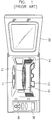
Figure 1 is a front view of a known microwave oven. As shown in Figure 1, the known microwave oven includes a cooking chamber 10 in which food is cooked, a cooking chamber door 20 for providing access to the cooking chamber 10, a rotary motor (not illustrated), a rotary stand 11 connected with the rotary motor, and a tray 12 positioned on the rotary stand 11, and on which the food is placed for cooking.
The known microwave oven also includes a heater 13 for grilling food, a thermistor 14 which senses the temperature of the cooking chamber 10, a control panel having a display 30 showing operational information of the microwave oven and a function selection part 40, a magnetron antenna (not shown) for supplying microwave energy to the cooking chamber 10 and which is mounted to an upper portion of a sidewall of the cooking chamber 10, and a magnetron (not shown) installed in a space at the rear of the display 30 for generating microwave energy and supplying it to the magnetron antenna.
The heater 13 is mounted at the rear of the upper portion of the cooking chamber 10. The heater 13 is rotatable and is held in place by supporting members provided on the side walls of the cooking chamber 10. When a user cooks with the heater 13, a cooking chamber lamp (not shown) is switched on to illuminate the cooking chamber 10, and the tray 11 rotates. Heat is produced when electricity is applied to the heater 13. When the programmed cooking time is complete, the electricity applied to the heater 13 is shut off, and the heater 13 stops producing heat. When the cooking operation is complete, the microwave oven informs the user.
The know microwave oven with the heater 13 maintains a high temperature for a predetermined period of time even after the cooking time has finished. Since the known microwave oven has no means to measure the temperature of the heater 13, which falls slowly when power is removed, a user does not know how much hotter than the air in the cooking chamber 10 the heater 13 is. Thus, when a user tries to cook food with the known microwave oven before the heater 13 cools, he may touch the hot heater 13 as he either puts food into or takes food out of the cooking chamber 10. If his or her hand touches the heater 13, he or she may get burnt and instantaneously drop the food that he or she is holding, thus making the cooking chamber 10 dirty.
It is an aim of the present invention to ameliorate the aforementioned problem.
A microwave oven according to the present invention is characterised by a temperature sensor for sensing the temperature of the heater element and alarm means responsive to opening of the door and the temperature sensor to produce an alarm signal if the temperature sensor indicates that the heater element is above a predetermined temperature when the door is being opened.
Preferably, a switch is used for detecting opening of the door. However, a piezoelectric element could be used instead.
The temperature sensor preferably comprises a bimetal temperature sensor or a thermistor. If a thermistor is being used, the temperature sensor outputs a voltage related to the surface temperature of the heater element, a control unit compares this voltage with a reference voltage corresponding to a reference temperature, and controls the generation of the alarm.
Embodiments of the present invention will now be described, by way of example, with reference to Figures 2 to 5 of the accompanying drawings, in which:
  • Figure 1 is a front view of a prior art microwave oven;
  • Figure 2 is a front view of a microwave oven in accordance with the present invention;
  • Figure 3 is a circuit diagram of a driver circuit for a safety system of a microwave oven in accordance with the present invention;
  • Figure 4 depicts the control sequence of the driver circuit of Figure 3; and
  • Figure 5 is a circuit diagram of a microwave oven in accordance with the present invention.
  • In the following description, parts described above with reference to a prior art microwave oven will not be described again. However, the same reference numerals will be used.
    Referring first to Figure 2, a microwave oven includes a heater temperature sensor 15 for checking the temperature of a heater 13, and this heater temperature sensor 15 is disposed on the cooking chamber 10's ceiling close to the heater 13.
    A function selection part 40 and display 30 are provided at the front of the microwave oven to allow a user to control the oven and confirm its operation with ease. The function selection part 40 has a cooking selection switch, a grill mode selection switch, and a power switch.
    The display 30 shows a user the control information programmed using the function selection part 40, and includes a visual alarm 50-1 which gives a user a warning if the temperature of the heater 13 is high when he or she opens a door 20 of the microwave oven. An audio alarm 50-2 such as a buzzer is provided at the bottom righthand corner of the display 30.
    Figure 3 is a circuit diagram of the inventive safety system, including the heater temperature sensor 15 for checking the temperature of the heater 13, and visual and audio alarms 50-1 and 50-2.
    As shown in Figure 3, the safety system includes a control unit 90 to which the heater temperature sensor 15 is coupled in series with a resistor R therebetween, and an alarm device 50 that is operated by an output signal of the control unit 90. The control unit 90 controls the alarm device 50 according to the value of the voltage output by the heater temperature sensor 15 that checks the temperature of the heater. A reference temperature for the heater temperature sensor 15 is set to 50°C. The reference temperature of the heater temperature sensor 15 is set to a value that will avoid a user from getting a burn when he or she touches the heater 13.
    As shown in Figure 3, the alarm device 50 consists of the visual alarm 50-1 and the audio alarm 50-2. The heater temperature sensor 15 is provided to the inside of the cooking chamber 10 for measuring the temperature of the heater 13. This is done with a thermistor, a temperature sensitive resistor. The thermistor has a high negative temperature coefficient of resistance, so that its resistance decreases as the temperature increases.
    In case that the heater 13 of the heater temperature sensor 15 is set to 50°C, if the temperature of the heater 13 is higher than the reference temperature, 50°C, the control unit 90 sounds the alarm device 50. If the temperature of the heater 13 drops to 50°C or less, the control unit 90 stops the alarm device 50. For example, once a constant voltage of 5V is applied across the heater temperature sensor 15 of 50°C, the control unit 90 detects a value of 2.5V or less. Accordingly, the control unit 90 compares the applied voltage with the preset voltage of 2.5V. If it determines that the applied voltage is lower than the preset voltage, it interprets that the temperature of the heater 13 is higher than the reference temperature, 50°C, and applies a driving signal to the alarm device 50.
    If the temperature of the heater 13 decreases below the reference temperature, the heater temperature sensor's temperature also drops. Thus, the sensor's resistance decreases according to the drop in the heater temperature sensor's temperature, and the control unit 90 detects a voltage of 2.5V or over. The control unit 90 compares the applied voltage with the preset voltage of 2.5V, and if it determines that the applied voltage is higher than the preset voltage, it decides that the temperature of the heater 13 is lower than the reference temperature, 50°C, and does not operate the alarm device 50.
    The operation of the above-described apparatus will now be described.
    Referring to Figure 4, if a user selects cooking using the heater 13, by means of the function selection part 40, the control unit 90 controls the power applied to the heater 13 so that the heater 13 produces heat. The display 30 then shows the user the programmed control information on the function selection part 40. When the programmed cooking time is over, the power applied to the heater 13 is shut off so that the heater 13 and the user is informed that cooking has been completed. The user then removes the cooked food from the cooking chamber 10.
    The user may open the door 20 during cooking in order to inspect the cooking process or to bring the food out of the cooking chamber 10.
    If the door 20 is opened, the control unit 90 senses it (Step 100). Once the control unit 90 senses (Step 100) that the door 20 is being opened, it detects (Step 200) the temperature of the heater 13 periodically using the heater temperature sensor 15. If the control unit 90 does not sense the door 20 continuing to be opened, it returns to the initial stage. The control unit 90 then determines (Step 300) if the temperature of the heater 13 that it measured at Step 200 is higher than the preset reference temperature (50°C). As described above with reference to Figure 3, the control unit 90 checks if a voltage of 2.5V or less is detected when a voltage of 5V is applied to the heater temperature sensor 15.
    If the control unit 90 detects the voltage of 2.5V or less, it determines (Step 300) that the temperature of the heater 13 is higher than the preset reference temperature (50°C) and sets the alarm device 50 off (Step 400). More specifically, the lamp of the display 30, the visual alarm device 50-1, is switched on, and the audio alarm device 50-1, the buzzer, is turned on. If a user puts his or her hand in the cooking chamber 10 in order to either take the food out of the cooking chamber 10 or put food in the cooking chamber 10, the alarm device 50 lets the user know that the heater 13 is still hot, thus preventing him or her from being burnt. If, on the other hand, the control unit 90 it detects a voltage of greater than 2.5V, it determines that the temperature of the heater 13 is lower than the preset reference temperature (50°C) at Step 300, maintains the alarm device 50 in its off condition (Step 500), and then returns to the initial stage.
    If the control unit 90 determines that the temperature of the heater 13 is higher than the preset reference temperature (50′′C) at Step 300, and then returns to the initial stage with the alarm device turned on at Step 400, it continuously checks (Step 200) the temperature of the heater 13 periodically. The control unit 90 also compares (Step 300) the detected temperature with the preset reference temperature. if the control unit 90 determines that the detected temperature is lower than the preset reference temperature, it controls the power applied to the alarm device 50, thus stopping its operation (Step 500). In case that the control unit 90 determines that the detected temperature is higher than or equal to the preset reference temperature, it keeps operating the alarm device 50 (Step 400). As the control unit 90 senses that the door 20 is closed by the user, it controls the power applied across the alarm device 50, thus stopping its operation.
    Another preferred embodiment of the present invention is now described referring to Figure 5.
    A driver circuit for the safety system includes a bimetal sensor 151 serving to open and close its contact at a given point of temperature, and a door switch 70 sensing the opening and closing of the door 20, and an alarm device 50. Once the temperature of the heater 13 within the cooking chamber 10 increases to a predetermined point or over, the bimetal sensor 151, made of two laminas with different coefficients of thermal expansion, closes its contact to turn on the driver circuit for the safety system. If the temperature of the heater 13 goes down to a predetermined point and downward, the bimetal sensor 151 opens its contact to turn off the driver circuit. The door switch 70 is operated by a push button, and opening and closing the door 20 turns the driver circuit on and off.
    Thus, when the control unit 90 senses that the temperature of the heater 13 increases to a predetermined point and the door 20 is opened, it closes the'driver circuit to drive the alarm device 50. If the user opens the door 20 when the temperature of the heater 13 is higher than the predetermined point, the control unit 90 drives the alarm device 50 so that a warning is given to him or her.
    As described above, the extra heater temperature sensor is provided to a microwave oven for measuring the temperature of the heater only. When the door of the microwave oven is opened, the heater temperature sensor measures the temperature of the heater. If the measured heater temperature is high enough to burn the user if he or she touches the heater, the alarm device gives a warning to him or her when he or she puts a foodstuff in the cooking chamber or takes it out. In such a manner, the present invention prevents the user from being burnt by the hot heater.

    Claims (8)

    1. A microwave oven having a radiant heater element (13) located in a cooking chamber (10) and a door (20) to the cooking chamber, characterised by a temperature sensor (15; 15') for sensing the temperature of the heater element (13) and alarm means (50, 50-1, 50-2) responsive to opening of the door (20) and the temperature sensor (15; 15') to produce an alarm signal if the temperature sensor (15; 15') indicates that the heater element (13) is above a predetermined temperature when the door (20) is being opened.
    2. An oven according to claim 1, including a switch (70; 70') for detecting opening of the door (20).
    3. An oven according to claim 1 or 2, wherein the temperature sensor (15; 15') comprises a bimetal temperature sensor (15').
    4. An oven according to claim 1 or 2, wherein the temperature sensor (15; 15') comprises a thermistor (15).
    5. In a microwave oven having a main body, a cooking chamber provided to the main body, a door for opening and closing the cooking chamber, a heater located on an upper portion of the cooking chamber for cooking a foodstuff utilizing direct heat, and a temperature sensor sensing the overall internal temperature of the cooking chamber, a safety system for the microwave oven comprising:
      heater temperature sensing means for measuring a surface temperature of the heater;
      a door switch for sensing the opening and closing of the door;
      control means receiving a signal output from each of the door switch and the heater temperature sensing means, and determining if the surface temperature of the heater is higher than a preset reference temperature and the door switch is turned on; and
      alarm means giving a warning to a user if the control means determines that the surface temperature of the heater is higher than a preset reference temperature and the door switch is turned on as the door is opened.
    6. A safety system for a microwave oven with a heater as set forth in claim 5, wherein the heater temperature sensing means is made of a bimetal of two metals, having different thermal expansion coefficients that curved by a difference in the thermal expansion coefficients if a temperature increases.
    7. A safety system for a microwave oven with a heater as set forth in claim 5, wherein the heater temperature sensing means is made of a thermistor, a temperature-sensitive resistor whose resistance decreases as the temperature increases.
    8. A safety system for a microwave oven with a heater as set forth in claim 5, wherein if the heater temperature sensing means outputs a value of voltage corresponding to the surface temperature of the heater, the control means compares said value of voltage with a value of voltage corresponding to the preset reference temperature, and controls the alarm means.
    EP97309544A 1997-01-11 1997-11-26 Microwave oven with safety system Withdrawn EP0854661A3 (en)

    Applications Claiming Priority (2)

    Application Number Priority Date Filing Date Title
    KR9700602 1997-01-11
    KR1019970000602A KR19980065545A (en) 1997-01-11 1997-01-11 Safety device for cooker with heater

    Publications (2)

    Publication Number Publication Date
    EP0854661A2 true EP0854661A2 (en) 1998-07-22
    EP0854661A3 EP0854661A3 (en) 1999-01-07

    Family

    ID=19494488

    Family Applications (1)

    Application Number Title Priority Date Filing Date
    EP97309544A Withdrawn EP0854661A3 (en) 1997-01-11 1997-11-26 Microwave oven with safety system

    Country Status (4)

    Country Link
    US (1) US5968402A (en)
    EP (1) EP0854661A3 (en)
    JP (1) JPH10205771A (en)
    KR (1) KR19980065545A (en)

    Cited By (3)

    * Cited by examiner, † Cited by third party
    Publication number Priority date Publication date Assignee Title
    WO2002056640A2 (en) * 2001-01-11 2002-07-18 General Electric Company Thermal/convection oven including halogen lamps
    EP1635616A1 (en) * 2004-09-13 2006-03-15 LG Electronics Inc. Microwave oven comprising a pivotable radiant heater
    CN105351983A (en) * 2015-12-15 2016-02-24 镇江市京口润明微波器械厂 Anti-scalding microwave oven

    Families Citing this family (13)

    * Cited by examiner, † Cited by third party
    Publication number Priority date Publication date Assignee Title
    US6677562B2 (en) * 2001-03-13 2004-01-13 Matsushita Electric Industrial Co., Ltd. High-frequency heating apparatus and cooling system for magnetron-driving power supply utilized in the apparatus
    KR100478455B1 (en) 2002-08-19 2005-03-22 삼성전자주식회사 Microwave Oven
    KR20040017188A (en) * 2002-08-20 2004-02-26 삼성전자주식회사 Cooking apparatus having heater
    KR20040017186A (en) 2002-08-20 2004-02-26 삼성전자주식회사 Cooking apparatus having heater
    CN100433944C (en) * 2003-02-21 2008-11-12 乐金电子(天津)电器有限公司 Temperature and door induction circuit for microwave oven
    KR100823296B1 (en) * 2003-03-28 2008-04-18 삼성전자주식회사 Display apparatus
    KR20040096201A (en) * 2003-05-07 2004-11-16 삼성전자주식회사 Baking machine and method of controlling the same
    US7244916B2 (en) 2004-01-14 2007-07-17 Sharp Kabushiki Kaisha Microwave heating and cooking apparatus including drawer body
    US7321309B2 (en) * 2005-04-26 2008-01-22 Kimberly-Clark Worldwide, Inc. System for delivering pain without causing physiological damage
    EP1754862A1 (en) * 2005-08-17 2007-02-21 ABB Turbo Systems AG Compressor, compressor wheel, washing attachment and exhaust turbocharger
    US20110095016A1 (en) * 2009-10-23 2011-04-28 Standex International Corporation Safe product transfer apparatus
    KR101552888B1 (en) * 2013-12-19 2015-09-14 동부대우전자 주식회사 Method and apparatus for controlling state of cooking device
    US11744956B2 (en) 2017-07-07 2023-09-05 Becton, Dickinson And Company Medical sharp removal and storage device

    Citations (3)

    * Cited by examiner, † Cited by third party
    Publication number Priority date Publication date Assignee Title
    JPH03144217A (en) * 1989-10-27 1991-06-19 Toshiba Corp Heater-cooker
    JPH0571745A (en) * 1991-09-10 1993-03-23 Toshiba Corp Cooking oven
    JPH08261479A (en) * 1995-03-22 1996-10-11 Sanyo Electric Co Ltd Cooking device

    Family Cites Families (3)

    * Cited by examiner, † Cited by third party
    Publication number Priority date Publication date Assignee Title
    NL165838C (en) * 1976-02-06 1981-05-15 Haarlem Keramisch Inst CERAMIC COOKING.
    JPS55119391A (en) * 1979-03-06 1980-09-13 Sharp Kk Cooking oven
    US5528018A (en) * 1991-08-19 1996-06-18 Henny Penny Corporation Programmable load compensation method and apparatus for use in a food

    Patent Citations (3)

    * Cited by examiner, † Cited by third party
    Publication number Priority date Publication date Assignee Title
    JPH03144217A (en) * 1989-10-27 1991-06-19 Toshiba Corp Heater-cooker
    JPH0571745A (en) * 1991-09-10 1993-03-23 Toshiba Corp Cooking oven
    JPH08261479A (en) * 1995-03-22 1996-10-11 Sanyo Electric Co Ltd Cooking device

    Non-Patent Citations (3)

    * Cited by examiner, † Cited by third party
    Title
    PATENT ABSTRACTS OF JAPAN vol. 015, no. 366 (M-1158), 13 September 1991 & JP 03 144217 A (TOSHIBA CORP), 19 June 1991 *
    PATENT ABSTRACTS OF JAPAN vol. 017, no. 395 (M-1451), 23 July 1993 & JP 05 071745 A (TOSHIBA CORP), 23 March 1993 *
    PATENT ABSTRACTS OF JAPAN vol. 097, no. 002, 28 February 1997 & JP 08 261479 A (SANYO ELECTRIC CO LTD), 11 October 1996 *

    Cited By (4)

    * Cited by examiner, † Cited by third party
    Publication number Priority date Publication date Assignee Title
    WO2002056640A2 (en) * 2001-01-11 2002-07-18 General Electric Company Thermal/convection oven including halogen lamps
    WO2002056640A3 (en) * 2001-01-11 2003-04-17 Gen Electric Thermal/convection oven including halogen lamps
    EP1635616A1 (en) * 2004-09-13 2006-03-15 LG Electronics Inc. Microwave oven comprising a pivotable radiant heater
    CN105351983A (en) * 2015-12-15 2016-02-24 镇江市京口润明微波器械厂 Anti-scalding microwave oven

    Also Published As

    Publication number Publication date
    JPH10205771A (en) 1998-08-04
    KR19980065545A (en) 1998-10-15
    EP0854661A3 (en) 1999-01-07
    US5968402A (en) 1999-10-19

    Similar Documents

    Publication Publication Date Title
    EP0854661A2 (en) Microwave oven with safety system
    US4874928A (en) A heating apparatus for automatically distinguishing the condition of food to be reheated
    KR100306552B1 (en) Cooking device with demonstration mode
    US5545880A (en) Method for automatic control of a microwave oven
    JPH0781713B2 (en) microwave
    JP4735276B2 (en) High frequency heating device
    US5595673A (en) Microwave oven with microwave-actuable bottom and temperature sensor
    CN1188212A (en) Safety system for microwave oven with heater
    CN103080655A (en) Radio frequency heating apparatus
    JPH08312966A (en) Cooking heater
    JP3022338B2 (en) Electric rice cooker
    JPS5828499B2 (en) Microwave oven with heater
    KR0154646B1 (en) Alarm method of door open for microwave oven
    JPS61262526A (en) Heating equipment
    KR0146131B1 (en) Automatic cooking device of microwave oven
    JP2518127B2 (en) High frequency heating cooker
    JP2570061B2 (en) High frequency heating equipment
    KR970006078B1 (en) Auto cooking control method of microwave oven
    JPH06338388A (en) Microwave oven
    JP2024022270A (en) microwave oven
    KR100499478B1 (en) Microwave oven having toaster function and method for controlling the same
    JP3008389B2 (en) Cooking device
    JP3246202B2 (en) High frequency heater
    KR100939719B1 (en) Method for Controlling Cook of Toaster
    JP2004242882A (en) Grill device

    Legal Events

    Date Code Title Description
    PUAI Public reference made under article 153(3) epc to a published international application that has entered the european phase

    Free format text: ORIGINAL CODE: 0009012

    AK Designated contracting states

    Kind code of ref document: A2

    Designated state(s): AT BE CH DE DK ES FI FR GB GR IE IT LI LU MC NL PT SE

    AX Request for extension of the european patent

    Free format text: AL;LT;LV;MK;RO;SI

    PUAL Search report despatched

    Free format text: ORIGINAL CODE: 0009013

    AK Designated contracting states

    Kind code of ref document: A3

    Designated state(s): AT BE CH DE DK ES FI FR GB GR IE IT LI LU MC NL PT SE

    AX Request for extension of the european patent

    Free format text: AL;LT;LV;MK;RO;SI

    AKX Designation fees paid
    STAA Information on the status of an ep patent application or granted ep patent

    Free format text: STATUS: THE APPLICATION IS DEEMED TO BE WITHDRAWN

    18D Application deemed to be withdrawn

    Effective date: 19990708

    REG Reference to a national code

    Ref country code: DE

    Ref legal event code: 8566