EP0854551A2 - Système laser à trois niveaux - Google Patents
Système laser à trois niveaux Download PDFInfo
- Publication number
- EP0854551A2 EP0854551A2 EP98100548A EP98100548A EP0854551A2 EP 0854551 A2 EP0854551 A2 EP 0854551A2 EP 98100548 A EP98100548 A EP 98100548A EP 98100548 A EP98100548 A EP 98100548A EP 0854551 A2 EP0854551 A2 EP 0854551A2
- Authority
- EP
- European Patent Office
- Prior art keywords
- laser
- gain
- gain medium
- layer
- radiation
- Prior art date
- Legal status (The legal status is an assumption and is not a legal conclusion. Google has not performed a legal analysis and makes no representation as to the accuracy of the status listed.)
- Granted
Links
Images


Classifications
-
- H—ELECTRICITY
- H01—ELECTRIC ELEMENTS
- H01S—DEVICES USING THE PROCESS OF LIGHT AMPLIFICATION BY STIMULATED EMISSION OF RADIATION [LASER] TO AMPLIFY OR GENERATE LIGHT; DEVICES USING STIMULATED EMISSION OF ELECTROMAGNETIC RADIATION IN WAVE RANGES OTHER THAN OPTICAL
- H01S3/00—Lasers, i.e. devices using stimulated emission of electromagnetic radiation in the infrared, visible or ultraviolet wave range
- H01S3/05—Construction or shape of optical resonators; Accommodation of active medium therein; Shape of active medium
- H01S3/06—Construction or shape of active medium
- H01S3/0602—Crystal lasers or glass lasers
- H01S3/0617—Crystal lasers or glass lasers having a varying composition or cross-section in a specific direction
-
- H—ELECTRICITY
- H01—ELECTRIC ELEMENTS
- H01S—DEVICES USING THE PROCESS OF LIGHT AMPLIFICATION BY STIMULATED EMISSION OF RADIATION [LASER] TO AMPLIFY OR GENERATE LIGHT; DEVICES USING STIMULATED EMISSION OF ELECTROMAGNETIC RADIATION IN WAVE RANGES OTHER THAN OPTICAL
- H01S3/00—Lasers, i.e. devices using stimulated emission of electromagnetic radiation in the infrared, visible or ultraviolet wave range
- H01S3/09—Processes or apparatus for excitation, e.g. pumping
- H01S3/091—Processes or apparatus for excitation, e.g. pumping using optical pumping
- H01S3/094—Processes or apparatus for excitation, e.g. pumping using optical pumping by coherent light
- H01S3/0941—Processes or apparatus for excitation, e.g. pumping using optical pumping by coherent light of a laser diode
-
- H—ELECTRICITY
- H01—ELECTRIC ELEMENTS
- H01S—DEVICES USING THE PROCESS OF LIGHT AMPLIFICATION BY STIMULATED EMISSION OF RADIATION [LASER] TO AMPLIFY OR GENERATE LIGHT; DEVICES USING STIMULATED EMISSION OF ELECTROMAGNETIC RADIATION IN WAVE RANGES OTHER THAN OPTICAL
- H01S3/00—Lasers, i.e. devices using stimulated emission of electromagnetic radiation in the infrared, visible or ultraviolet wave range
- H01S3/02—Constructional details
- H01S3/04—Arrangements for thermal management
- H01S3/042—Arrangements for thermal management for solid state lasers
-
- H—ELECTRICITY
- H01—ELECTRIC ELEMENTS
- H01S—DEVICES USING THE PROCESS OF LIGHT AMPLIFICATION BY STIMULATED EMISSION OF RADIATION [LASER] TO AMPLIFY OR GENERATE LIGHT; DEVICES USING STIMULATED EMISSION OF ELECTROMAGNETIC RADIATION IN WAVE RANGES OTHER THAN OPTICAL
- H01S3/00—Lasers, i.e. devices using stimulated emission of electromagnetic radiation in the infrared, visible or ultraviolet wave range
- H01S3/05—Construction or shape of optical resonators; Accommodation of active medium therein; Shape of active medium
- H01S3/06—Construction or shape of active medium
- H01S3/0602—Crystal lasers or glass lasers
- H01S3/0606—Crystal lasers or glass lasers with polygonal cross-section, e.g. slab, prism
-
- H—ELECTRICITY
- H01—ELECTRIC ELEMENTS
- H01S—DEVICES USING THE PROCESS OF LIGHT AMPLIFICATION BY STIMULATED EMISSION OF RADIATION [LASER] TO AMPLIFY OR GENERATE LIGHT; DEVICES USING STIMULATED EMISSION OF ELECTROMAGNETIC RADIATION IN WAVE RANGES OTHER THAN OPTICAL
- H01S3/00—Lasers, i.e. devices using stimulated emission of electromagnetic radiation in the infrared, visible or ultraviolet wave range
- H01S3/10—Controlling the intensity, frequency, phase, polarisation or direction of the emitted radiation, e.g. switching, gating, modulating or demodulating
- H01S3/105—Controlling the intensity, frequency, phase, polarisation or direction of the emitted radiation, e.g. switching, gating, modulating or demodulating by controlling the mutual position or the reflecting properties of the reflectors of the cavity, e.g. by controlling the cavity length
- H01S3/1053—Control by pressure or deformation
-
- H—ELECTRICITY
- H01—ELECTRIC ELEMENTS
- H01S—DEVICES USING THE PROCESS OF LIGHT AMPLIFICATION BY STIMULATED EMISSION OF RADIATION [LASER] TO AMPLIFY OR GENERATE LIGHT; DEVICES USING STIMULATED EMISSION OF ELECTROMAGNETIC RADIATION IN WAVE RANGES OTHER THAN OPTICAL
- H01S5/00—Semiconductor lasers
- H01S5/06—Arrangements for controlling the laser output parameters, e.g. by operating on the active medium
- H01S5/068—Stabilisation of laser output parameters
- H01S5/0683—Stabilisation of laser output parameters by monitoring the optical output parameters
-
- H—ELECTRICITY
- H01—ELECTRIC ELEMENTS
- H01S—DEVICES USING THE PROCESS OF LIGHT AMPLIFICATION BY STIMULATED EMISSION OF RADIATION [LASER] TO AMPLIFY OR GENERATE LIGHT; DEVICES USING STIMULATED EMISSION OF ELECTROMAGNETIC RADIATION IN WAVE RANGES OTHER THAN OPTICAL
- H01S3/00—Lasers, i.e. devices using stimulated emission of electromagnetic radiation in the infrared, visible or ultraviolet wave range
- H01S3/02—Constructional details
- H01S3/025—Constructional details of solid state lasers, e.g. housings or mountings
-
- H—ELECTRICITY
- H01—ELECTRIC ELEMENTS
- H01S—DEVICES USING THE PROCESS OF LIGHT AMPLIFICATION BY STIMULATED EMISSION OF RADIATION [LASER] TO AMPLIFY OR GENERATE LIGHT; DEVICES USING STIMULATED EMISSION OF ELECTROMAGNETIC RADIATION IN WAVE RANGES OTHER THAN OPTICAL
- H01S3/00—Lasers, i.e. devices using stimulated emission of electromagnetic radiation in the infrared, visible or ultraviolet wave range
- H01S3/02—Constructional details
- H01S3/04—Arrangements for thermal management
- H01S3/0407—Liquid cooling, e.g. by water
-
- H—ELECTRICITY
- H01—ELECTRIC ELEMENTS
- H01S—DEVICES USING THE PROCESS OF LIGHT AMPLIFICATION BY STIMULATED EMISSION OF RADIATION [LASER] TO AMPLIFY OR GENERATE LIGHT; DEVICES USING STIMULATED EMISSION OF ELECTROMAGNETIC RADIATION IN WAVE RANGES OTHER THAN OPTICAL
- H01S3/00—Lasers, i.e. devices using stimulated emission of electromagnetic radiation in the infrared, visible or ultraviolet wave range
- H01S3/05—Construction or shape of optical resonators; Accommodation of active medium therein; Shape of active medium
- H01S3/06—Construction or shape of active medium
- H01S3/0602—Crystal lasers or glass lasers
- H01S3/0612—Non-homogeneous structure
-
- H—ELECTRICITY
- H01—ELECTRIC ELEMENTS
- H01S—DEVICES USING THE PROCESS OF LIGHT AMPLIFICATION BY STIMULATED EMISSION OF RADIATION [LASER] TO AMPLIFY OR GENERATE LIGHT; DEVICES USING STIMULATED EMISSION OF ELECTROMAGNETIC RADIATION IN WAVE RANGES OTHER THAN OPTICAL
- H01S3/00—Lasers, i.e. devices using stimulated emission of electromagnetic radiation in the infrared, visible or ultraviolet wave range
- H01S3/05—Construction or shape of optical resonators; Accommodation of active medium therein; Shape of active medium
- H01S3/08—Construction or shape of optical resonators or components thereof
- H01S3/08095—Zig-zag travelling beam through the active medium
-
- H—ELECTRICITY
- H01—ELECTRIC ELEMENTS
- H01S—DEVICES USING THE PROCESS OF LIGHT AMPLIFICATION BY STIMULATED EMISSION OF RADIATION [LASER] TO AMPLIFY OR GENERATE LIGHT; DEVICES USING STIMULATED EMISSION OF ELECTROMAGNETIC RADIATION IN WAVE RANGES OTHER THAN OPTICAL
- H01S3/00—Lasers, i.e. devices using stimulated emission of electromagnetic radiation in the infrared, visible or ultraviolet wave range
- H01S3/10—Controlling the intensity, frequency, phase, polarisation or direction of the emitted radiation, e.g. switching, gating, modulating or demodulating
- H01S3/10076—Controlling the intensity, frequency, phase, polarisation or direction of the emitted radiation, e.g. switching, gating, modulating or demodulating using optical phase conjugation, e.g. phase conjugate reflection
-
- H—ELECTRICITY
- H01—ELECTRIC ELEMENTS
- H01S—DEVICES USING THE PROCESS OF LIGHT AMPLIFICATION BY STIMULATED EMISSION OF RADIATION [LASER] TO AMPLIFY OR GENERATE LIGHT; DEVICES USING STIMULATED EMISSION OF ELECTROMAGNETIC RADIATION IN WAVE RANGES OTHER THAN OPTICAL
- H01S3/00—Lasers, i.e. devices using stimulated emission of electromagnetic radiation in the infrared, visible or ultraviolet wave range
- H01S3/23—Arrangements of two or more lasers not provided for in groups H01S3/02 - H01S3/22, e.g. tandem arrangements of separate active media
- H01S3/2308—Amplifier arrangements, e.g. MOPA
- H01S3/2325—Multi-pass amplifiers, e.g. regenerative amplifiers
- H01S3/2333—Double-pass amplifiers
Definitions
- the present invention relates to solid state lasers and, more particularly, to high energy, long coherence length eyesafe lasers.
- Solid state laser gain modules comprise a housing enclosing a solid state laser gain medium such as neodymium yttrium aluminum garnet (Nd:YAG) or neodymium glass, and an optical pumping source for pumping species in the laser gain medium to produce a population inversion.
- the laser gain medium includes optical pump regions for receiving radiation from the optical pumping source.
- the optical pumping source is typically a light source which emits over a broad spectrum of wavelengths. Since optical pumping generates a large amount of heat within the laser gain medium and increases the medium's temperature, a cooling system is utilized to control the temperature in the pump regions of the laser gain medium.
- the laser gain medium typically has a slab configuration and a rectangular cross-section, and includes optically polished major side and end faces, and lateral pump faces perpendicular to the major side faces.
- An input light wave impinges on an edge face of the laser gain medium and the electromagnetic radiation emitted by the pumping source impinges upon the pump faces of the laser gain medium to excite the active species to create a population inversion.
- the interaction of the input light wave with excited atoms amplifies the light wave.
- the light wave is passed generally along the longitudinal axis of the gain medium by multiple internal zig-zag reflections from the major side faces. These internal reflections average out thermal gradients in the laser gain medium.
- the light wave is amplified each time it passes through the gain medium to increase gain.
- the laser gain medium is typically retained in the gain module using holders which contact the pump faces of the gain medium. Further, sealing means are used to seal coolant flowing across the pump faces of the gain medium.
- the holders and the sealing means block the pump faces from receiving radiation from the optical pump source. The blocked areas form unpumped regions which cause significant losses in laser energy only for 3-level lasers. This is not true for 4-level lasers such as Nd:YAG.
- Diode lasers provide much closer matching of the absorption peak of the laser gain medium than is possible with broadband lamps. This improved wavelength matching increases the efficiency of solid state laser gain mediums and reduces detrimental heating effects.
- the orientation of the diodes with respect to the crystal axis has a direct effect on the absorption of the pumping radiation by the gain medium.
- a uni-axial crystal typically has a principal radiation absorption axis along which the crystal displays significantly higher absorption of pumping radiation than along other axis of the crystal.
- a disadvantage of some conventional gain modules using uniaxial crystals is that the light emitting diodes are not optimally oriented with respect to the principal absorption axis of the uni-axial gain medium crystal to maximize absorption of pumping radiation by the gain medium crystal.
- Another disadvantage of conventional gain modules is loss of laser energy due to absorption of laser emissions in the cooling system.
- water has been utilized as a coolant to control the temperature of the gain medium.
- the pumping faces of the gain medium are cooled by flowing water over the pumping faces.
- the laser emissions are strongly absorbed by the cooling water. This causes substantial losses in the zig-zag slab, reducing the efficiency of the gain medium.
- zig-zag slabs generate evanescent waves which penetrate a short distance into the water coolant flowing across the pumping faces of the slab. Absorption of the evanescent waves by the cooling water attenuates the laser beam.
- the present invention satisfies these needs.
- the present invention provides a 3-level solid state laser gain medium for use in a laser gain module, wherein the gain medium comprises: (a) a gain layer having pump regions and a first and a second contact region, the gain layer generating laser radiation at a lasing wavelength in response to pumping radiation pulses at the pump regions; (b) a first transparent layer optically connected to the first contact region of the gain layer by diffusion bonding; and (c) a second transparent layer optically connected to the second contact region of the gain layer by diffusion bonding.
- the transparent layers are transparent to the lasing wavelength to reduce absorption of the laser radiation by the transparent layers.
- the transparent regions are sized to be retained by a retainer in the gain module or to cooperate with a sealing means for sealing coolants. As such, the retainer or sealing means do not block the pump regions of the gain layer and formation of lossy unpumped regions is prevented.
- the present invention also provides an apparatus for amplifying laser light, comprising: (a) a solid state, slab geometry gain medium having lateral pump faces and a principal radiation absorption axis; and (b) an excitation mechanism located along the pump faces of the gain medium to generate radiation polarized in parallel with the principal absorption axis of the gain medium for increased radiation absorption.
- the excitation mechanism comprises a set of laser diodes oriented to generate radiation intensity polarized in parallel with the principal absorption axis of the gain medium.
- the gain medium can be a uni-axial birefringent crystal having a c-axis, and wherein the principal radiation absorption axis is along the c-axis.
- the present invent on also provides an apparatus for amplifying laser light, comprising: (a) a solid state laser gain medium; (b) an excitation mechanism located proximate the solid state laser gain medium for producing radiation intensity to the gain medium, whereby the gain medium generates laser output laser emission at a wavelength from about 2 ⁇ m to about 3 ⁇ m; and (c) a cooling system located proximate the solid state laser gain medium to provide cooling of the gain medium, the cooling system including a coolant material for reducing absorption of the laser emission by the coolant at said wavelengths.
- the gain medium is a slab geometry solid state gain medium having pump faces, with the coolant flowing across the pump faces, wherein evanescent waves from the gain medium penetrating the coolant are substantially unabsorbed by the coolant.
- the coolant consists essentially of D 2 O.
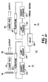
- a schematic diagram of a conventional laser oscillator-amplifier system 10 is shown.
- Laser energy is generated by gain in energy of a light beam making passes through an optically active material.
- the generation of high-energy pulses is based on the combination of a laser oscillator 12 and a laser amplifier 14.
- the amplifier 14 is driven by the oscillator 12 which generates an initial light pulse of moderate power and energy.
- the oscillator 12 includes a laser gain medium 16 such as a laser rod placed between two mirrors 18 one of which provides full reflection and the other partial reflection and partial transmission of light therethrough.
- a pumping source 20 such as a flash tube generates radiation pulses which are absorbed by the oscillator gain medium 16.
- the system further includes energy storage means 22, lamp triggers 24 and a delay means 26 for controlling the energy and firing sequence of the flash lamps for the oscillator 12 and the amplifier 14.
- the laser light energy is produced in the gain medium 16 by photonic emission from active or high energy level ions in the body of the gain medium 16, with the pump light increasing the number of ions from a lower energy level to an upper energy level.
- the pumping light energy abnormally increases the upper level population of ions and concomitantly depletes the lower level population of ions creating an inversion of energy states.
- Some of the ions in the upper energy level undergo a spontaneous light emissive transmission to the lower level, and the spontaneously emissive light reflects back and forth between the mirrored surfaces simulating similar light emissive transmissions from other upper level ions.
- the stimulated emission reflects back and forth repeatedly through the rod a sufficiently high intensity pulse of laser light energy is emitted by transmission through the partially reflective surface.
- the laser light pulse is directed to the amplifier 14 to significantly increase the power and energy of the laser light.
- the amplifier 14 incudes a gain medium 16 such as a laser rod which is exposed to the pumping radiation energy of a pumping source 20 such as a flash tube.
- the amplifier gain medium 16 is an optically active material in which the power of the pulse generated by the oscillator 12 can grow significantly as a result of the pumping radiation from the pumping source 20.
- the gain medium 16 includes pumping regions for receiving radiation energy from the pump source 20.
- the gain medium 16 is disposed in the oscillator 12 or the amplifier 14 gain module via holders which are in contact with the pump regions of the gain medium 16.
- the pump regions are also in contact with sealing means utilized to seal coolants flowing across the pump regions of the gain medium 16.
- the pump regions of the gain medium 16 are blocked from the pumping radiation of the pumping source 20, forming unpumped regions on the gain medium 16.
- the unpumped regions cause significant laser energy loss from the gain medium 16 at the unpumped region in 3-level lasers.
- the present invention provides a solid state laser gain, medium for use in a laser gain module with reduced laser energy loss.
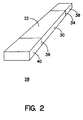
- Figs. 2 and 3 illustrate different views of an embodiment of a laser gain medium 28 according to the present invention.
- the laser gain medium 28 is illustrated in slab geometry form, the present invention contemplates other geometries such as rod or disk. As such, the gain medium 28 of the present invention is not limited to slab geometry in form.
- the laser gain medium 28 comprises: (a) a gain layer 30 having pump regions 32 and first and second contact regions 34 and 36, respectively, the gain layer 30 generating laser radiation at a lasing wavelength in response to pumping radiation pulses at the pump regions 32; (b) a first transparent layer 38 optically connected to the first contact region 34 of the gain layer 30 by diffusion bonding; and (c) a second transparent layer 40 optically connected to the second contact region 36 of the gain layer 30 by diffusion bonding.
- the transparent layers 38 and 40 are transparent to the lasing wavelength to reduce absorption of the laser radiation by the transparent layers 38 and 40.
- the transparent layers 38 and 40 can be sized to be retained by a retainer or to cooperate with a sealing means for sealing coolants. As such, the retainer or sealing means do not block the pump regions 32 of the gain layer 30 and prevent formation of lossy unpumped regions.
- the pumping regions 32 include lateral pumping faces and the contact regions 34 and 36 are substantially transverse to the lateral pumping faces.
- the gain layer 30 and the transparent layers 38 and 40 are of the same crystalline material.
- the crystal material can be selected from the group consisting essentially of YLF, YAG, YAP, YSGG, YSAG, GSGG, GGG, LiSAF, LiCAF, SFAP and glass.
- the gain layer 30 is ion doped and the transparent layers 38 and 40 are undoped.
- the dopant material can be selected from the group consisting essentially of holmium, thulium, chromium, erbium, and ytterbium.
- the doped regions are subjected to pump radiation from a pump source and the undoped regions are unpumped. As such the undoped regions can be utilized for holding the gain medium 28 and provide coolant sealing.
- Diffusion bonding provides optical homogeneity between the gain layer 30 and the transparent layers 38 and 40.
- the diffusion bonding process for the gain layer 30 and each of the transparent layers 38 and 40 can include: optically contacting the contact regions 34 and 36 of the gain layer 30 to the transparent layers 38 and 40, respectively, to form an assembly; bonding the optically contacted regions by gradually heating the regions to a temperature below the fusion temperature of the regions, but at a temperature and for a time sufficient to diffusion bond the regions; and cooling the bonded structure at a rate which allows the removal of stress by annealing.
- there is no bonding agent or bonding film is utilized between the bonded layers. Examples of diffusion bonding are described in U.S. Patent No. 5,441,803 which is Incorporated herein by reference.
- a laser gain medium 28 according to the present invention is particularly useful for zig-zag slab geometry gain mediums for three-level lasers.
- a three-level laser system initially, all atoms of the gain medium are in a lowest level. Excitation is provided by optical pumping radiation of frequencies which produce absorption into a broad band. Thus, the pump light raises atoms from the ground state to a pump band.
- the "pumping" band is made up of a number of bands, so that the optical pumping can be accomplished over a broad spectral range.
- the excited atoms are transferred by fast radiationless transitions into an intermediate sharp level. In this process the energy lost by an electron is transferred to the gain medium lattice. Finally, the excited atom returns to the ground level by the emission of a photon. This last transition that is responsible for the laser action. If pumping intensity is below laser threshold, atoms in the intermediate level predominantly return to the ground state by spontaneous emission. After the pump radiation is extinguished, the intermediate level is emptied at a rate that varies from material to material. When the pump intensity is above laser threshold, the decay from fluorescent level consists of stimulated as well as spontaneous radiation; the stimulated radiation produces the laser output beam.
- the transparent layers 38 and 40 of the gain medium 28 of the present invention advantageously provide transparent layers 38 and 40 of the gain medium 28 that are not pumped and can be utilized for holding and sealing.
- the transparent layers 38 and 40 eliminate ground state absorption and the associated laser energy loss.
- Example specification of a slab configuration gain medium 28 according to the present invention for use in a laser amplifier include:
- gain mediums often include uni-axial birefringent crystals.
- Many uni-axial crystals have a principal radiation absorption axis along which the crystal displays significantly higher absorption of pumping radiation than along other axis of the crystal.
- An example of such a crystal is Tm:Ho:YLF with significantly higher absorption of pumping radiation polarized along the c-axis of the crystal.
- Tm:Ho:YLF is a preferred host material for two-micron lasers because of its high gain per stored energy than other hosts such as Tm:Ho:YAG.
- YLF is a uni-axial birefringent crystal, it has specific crystal orientations. Therefore, diode emission polarization oriented along the c-axis of the crystal provides higher absorption than along the a-axis. As such, the orientation of optical pumping sources such as laser diodes with respect to the crystal axis has a direct effect on the absorption of the pumping radiation by the gain medium crystal.
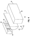
- the present invention provides an apparatus for amplifying laser light including an excitation mechanism optimally oriented with respect to the principal absorption axis of a uni-axial gain crystal to maximize absorption of pumping radiation by the crystal.
- an apparatus 40 comprises: (a) a solid state, slab geometry gain medium 44 having lateral pump faces 46 and a principal radiation absorption axis C; and (b) an excitation mechanism 48 located along the pump faces 46 of the gain medium 44 for generating polarized light along a polarization axis 52 wherein the polarization axis 52 is parallel with the principal absorption axis C of the gain medium 44 to provide increased radiation absorption.
- the excitation mechanism 48 preferably comprises set of diode arrays 50 oriented to generate radiation energy polarized along the axis 52.
- the gain medium 44 can be a uni-axial birefringent crystal having a c-axis, wherein the principal radiation absorption axis is along the c-axis.
- the crystal can be selected from the group consisting essentially of Tm:Ho:YLF, Yb:SFAP, Cr:LiSAF.
- the diodes 50 are vertically oriented and the radiation from the diodes 50 is polarized along the polarization axis 52, parallel to the c-axis of the crystal to yield maximum absorption.
- a cylindrical lens 54 can be used to focus the diode light in the vertical dimension to confine the pump beam to a smaller volume in the gain medium 44.
- An example specification for the diodes 50 shown in Fig. 4 includes:
- a substantial amount of pump light energy is necessary to produce laser light.
- the amount of pumping illumination required to produce laser action in ruby is approximately 500 watts per cubic centimeter of laser rod, and the amount required in neodymium glass is about 50 watts per cubic centimeters.
- the energy absorbed produces a considerable quantity of heat in the gain medium, and unless special precautions are taken for removal of this heat, deleterious temperature rises will result.
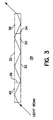
- Fig. 5 illustrates the end view of a zig-zag slab 56 with pump face cooling.
- zig-zag slabs are face-cooled with water to minimize temperature gradients as shown in Fig. 5.
- laser emissions from about 2 ⁇ m to about 3 ⁇ m are strongly absorbed by water.
- holmium and thulium emission at 2 ⁇ m and Erbium emission at 2.8 ⁇ m are strongly absorbed by water, causing substantial losses in the zig-zag slab.
- zig-zag slabs generate evanescent waves which penetrate a short distance into the coolant. The presence of a strong absorber at the surfaces of the slabs can attenuate the beam.
- the present invention provides a cooling system 58 for a solid state gain medium 60 generating laser output laser emission at a wavelength from about 2 ⁇ m to about 3 ⁇ m.
- the cooling system 58 is located proximate the gain medium 60 to provide cooling of the gain medium 60.
- the cooling system 58 of the present invention includes a coolant material for reducing absorption of laser emissions by the coolant at wavelengths from about 2 ⁇ m to about 3
- the gain medium 60 is a slab geometry solid state gain medium having pump faces, with the coolant flowing across the pump faces, wherein evanescent waves from the gain medium penetrating the coolant are substantially unabsorbed by the coolant.
- the coolant can be any material with minimal absorption of laser energy from about 2 ⁇ m to about 3 ⁇ m.
- the coolant consists essentially of D 2 O or liquid fluorocarbons. D 2 O is advantageous in that it has the good thermal properties of water, making it an ideal coolant, and yet with minimal absorption of evanescent waves at the above lasing wavelengths.
- the embodiment of the cooling system 58 of the present invention shown in Fig. 6 includes a pair of generally rectangular shaped windows 64, 66 disposed on opposite sides of the laser gain medium 60.
- the windows 64, 66 are adjacent and parallel to the laser gain medium 60 so as to define coolant flow channels 68, 70, through which a coolant is flowed longitudinally over major side faces 72, 74 of the laser gain medium 60.
- the windows 64, 66 are preferably composed of sapphire. Other suitable materials having thermal expansion properties close to those of sapphire may optionally be used.
- Seals 76, 78 are positioned at the upper and lower faces of the windows 64, 66, respectively, to seal the laser gain medium 60 as coolant is passed through the flow channels 68, 70.
- the seals 76, 78 are preferably composed of a pure silicone rubber material.
- the seals 76, 78 may optionally be formed of other suitable light transmitting materials.
- the seals 76, 78 are carefully positioned with respect to the laser gain medium 60 to minimize thermal gradients in the laser gain medium 60 that degrade optical performance.
- the gain medium 60 can be a gain medium according to present invention described above. In that case, the seals and any necessary holders can be positioned to be in contact with the transparent layers instead of the gain layer of the gain medium 60. As such, the seals or holders do not block pumping radiation.
- a coolant distribution system can be utilized to distribute coolant to the coolant flow channels 68, 70 between the respective windows 64, 66 and the laser gain medium 60.
- the coolant is preferably D 2 O or other equivalent coolants according to the present invention.
- the present invention contemplates other embodiments of a cooling system for cooling a solid state gain medium utilizing a coolant with reduced absorption of laser energy from about 2 ⁇ m to about 3 ⁇ m.
- Fig. 7 illustrates the cooling system of Fig. 6 including an excitation mechanism 62 located proximate a uni-axial birefringent crustal gain medium 60 for producing radiation intensity to the gain medium 60.
- the excitation mechanism 62 can comprise a set of diodes vertically oriented to generate radiation polarized along the c-axis of the crystal as described above.
- Fig. 8 illustrates a block diagram of a phase conjugated MOPA architecture laser system.
- the laser system includes a Master Oscillator (MO), a Faraday Rotator (FR), an amplifier or gain medium, an SBS cell and two image relay telescopes assembled as shown.
- the gain medium is a birefringent crystalline host material according to the present invention.
- the master oscillator provides a source of radiation that is injected into the amplifier where it is amplified to provide desired higher power output laser radiation.
- the master oscillator comprises a low energy, high phase front quality, and high spectral purity laser oscillator which provides pulses of laser radiation.
- the pulses have a duration and wavelength determined by the desired laser application as well as the type of oscillator medium used.
- the gain medium element is disposed along an optical path extending between a phase conjugate reflector (SBS cell) disposed on one end and an optical coupler on the other.
- SBS cell phase conjugate reflector
- the energy from the master oscillator is coupled into the gain medium using an optical coupler (Faraday Isolator) to selectively couple the output from the master oscillator along the optical path through the gain medium.
- the coupling means is also configured to prevent all but a very small percentage of radiation exiting the amplifier stage from re-entering the master oscillator.
- a pulse traversing the gain medium is amplified by creating emissions from energetically pumped atoms or molecules present. A similar process occurs for the reflected pulse.
- Gain in general is proportional to the stored energy in an amplifier gain medium.
- the extraction geometry of the amplifier is:
- the SBS cell specification includes:
- the gain medium is a slab having a rectangular cross-section, and includes optically polished major side and end faces, and lateral pump faces perpendicular to-the major side faces.
- the input light wave impinges on an edge face of the laser gain medium and the electromagnetic radiation emitted by a pumping source impinges upon the pump faces of the laser gain medium to excite the active species to create a population inversion.
- the pumping source includes laser diodes oriented as discussed above.
- the interaction of the light wave with the excited atoms amplifies the light wave.
- Coolant consisting essentially of D 2 O, is flowed across the faces of the slab by a cooling system described above.
Landscapes
- Physics & Mathematics (AREA)
- Electromagnetism (AREA)
- Optics & Photonics (AREA)
- Engineering & Computer Science (AREA)
- Plasma & Fusion (AREA)
- Chemical & Material Sciences (AREA)
- Crystallography & Structural Chemistry (AREA)
- Condensed Matter Physics & Semiconductors (AREA)
- General Physics & Mathematics (AREA)
- Lasers (AREA)
Applications Claiming Priority (2)
| Application Number | Priority Date | Filing Date | Title |
|---|---|---|---|
| US08/783,646 US5841805A (en) | 1997-01-14 | 1997-01-14 | Three-level laser system |
| US783646 | 1997-01-14 |
Publications (3)
| Publication Number | Publication Date |
|---|---|
| EP0854551A2 true EP0854551A2 (fr) | 1998-07-22 |
| EP0854551A3 EP0854551A3 (fr) | 1999-12-08 |
| EP0854551B1 EP0854551B1 (fr) | 2007-04-25 |
Family
ID=25129966
Family Applications (1)
| Application Number | Title | Priority Date | Filing Date |
|---|---|---|---|
| EP98100548A Expired - Lifetime EP0854551B1 (fr) | 1997-01-14 | 1998-01-14 | Système laser à trois niveaux |
Country Status (6)
| Country | Link |
|---|---|
| US (1) | US5841805A (fr) |
| EP (1) | EP0854551B1 (fr) |
| JP (1) | JP3234805B2 (fr) |
| KR (1) | KR19980070480A (fr) |
| CA (1) | CA2225982C (fr) |
| DE (1) | DE69837632T2 (fr) |
Cited By (7)
| Publication number | Priority date | Publication date | Assignee | Title |
|---|---|---|---|---|
| WO2003009440A2 (fr) * | 2001-07-20 | 2003-01-30 | Powerlase Limited | Appareil laser |
| US6956885B2 (en) | 2000-08-31 | 2005-10-18 | Powerlase Limited | Electromagnetic radiation generation using a laser produced plasma |
| EP1713149A1 (fr) * | 2005-04-12 | 2006-10-18 | Raython Company | Eléments laser soudés avec glaçure et leur procédé de fabrication |
| WO2007111794A2 (fr) * | 2006-03-23 | 2007-10-04 | Matsushita Electric Industrial Co., Ltd. | Système laser à oscillateur laser et à amplificateur laser pompés par une source unique |
| EP1864954A2 (fr) * | 2006-06-06 | 2007-12-12 | Kabushiki Kaisha Topcon | Procédé d'assemblage d'éléments optiques, structure d'intégration d'éléments optiques et dispositif d'oscillation laser |
| WO2007084111A3 (fr) * | 2005-01-12 | 2008-03-06 | Raytheon Co | Laser a semi-conducteurs a haute energie avec pompage deporte et geometrie d'extraction |
| CN111559048A (zh) * | 2020-04-25 | 2020-08-21 | 芜湖荣基实业有限公司 | 一种高分子塑料生产用熔接装置 |
Families Citing this family (10)
| Publication number | Priority date | Publication date | Assignee | Title |
|---|---|---|---|---|
| US6873639B2 (en) * | 1993-05-28 | 2005-03-29 | Tong Zhang | Multipass geometry and constructions for diode-pumped solid-state lasers and fiber lasers, and for optical amplifier and detector |
| US6134258A (en) * | 1998-03-25 | 2000-10-17 | The Board Of Trustees Of The Leland Stanford Junior University | Transverse-pumped sLAB laser/amplifier |
| JP2000082860A (ja) * | 1998-09-04 | 2000-03-21 | Toshiba Corp | 固体レーザ装置 |
| US6490081B1 (en) * | 2000-07-28 | 2002-12-03 | The Board Of Trustees Of The Leland Stanford Junior University | Method of amplifying optical signals using doped materials with extremely broad bandwidths |
| US7087447B2 (en) * | 2003-10-28 | 2006-08-08 | The Board Of Trustees Of The Leland Stanford Junior University | Method for fabricating zig-zag slabs for solid state lasers |
| US8702687B2 (en) * | 2005-11-03 | 2014-04-22 | Luxon, Inc. | Surgical laser systems for soft and hard tissue and methods of use thereof |
| JP5339172B2 (ja) * | 2006-11-15 | 2013-11-13 | 株式会社メガオプト | コヒーレントドップラーライダー |
| JP2010073936A (ja) * | 2008-09-19 | 2010-04-02 | Tokuyama Corp | 真空紫外発光素子 |
| JP2019186417A (ja) * | 2018-04-12 | 2019-10-24 | 大学共同利用機関法人自然科学研究機構 | レーザー装置 |
| US11349274B2 (en) | 2018-10-16 | 2022-05-31 | Lumentum Operations Llc | Amplifier assembly |
Citations (6)
| Publication number | Priority date | Publication date | Assignee | Title |
|---|---|---|---|---|
| US4233567A (en) * | 1978-12-13 | 1980-11-11 | General Electric Company | Face-cooled laser device having increased energy storage and output |
| US5394420A (en) * | 1994-01-27 | 1995-02-28 | Trw Inc. | Multiform crystal and apparatus for fabrication |
| EP0652616A1 (fr) * | 1993-11-05 | 1995-05-10 | Trw Inc. | Laser à matériau solide à haute brillance avec amplificateur à zig-zag |
| US5441803A (en) * | 1988-08-30 | 1995-08-15 | Onyx Optics | Composites made from single crystal substances |
| US5485482A (en) * | 1993-12-08 | 1996-01-16 | Selker; Mark D. | Method for design and construction of efficient, fundamental transverse mode selected, diode pumped, solid state lasers |
| WO1997017746A1 (fr) * | 1995-11-09 | 1997-05-15 | Barr & Stroud Limited | Laser a solide |
Family Cites Families (19)
| Publication number | Priority date | Publication date | Assignee | Title |
|---|---|---|---|---|
| US3611190A (en) * | 1969-10-16 | 1971-10-05 | American Optical Corp | Laser structure with a segmented laser rod |
| US5181223A (en) * | 1985-05-01 | 1993-01-19 | Spectra-Physics, Incorporated | High-efficiency mode-matched transversely-pumped solid state laser amplifier |
| US4713820A (en) * | 1985-08-02 | 1987-12-15 | Allied Corporation | Thermal lensing-compensated lanthanum beryllate laser |
| US4876694A (en) * | 1986-07-07 | 1989-10-24 | Advanced Lasers Limited | External cavity slab lasers |
| IL88722A (en) * | 1988-12-19 | 1993-03-15 | Israel State | Holmium laser |
| US5224116A (en) * | 1989-03-08 | 1993-06-29 | Bt&D Technologies Ltd. | Laser amplifier |
| US5148445A (en) * | 1989-04-24 | 1992-09-15 | Quantronix Corp. | High power Nd:YLF solid state lasers |
| US4949346A (en) * | 1989-08-14 | 1990-08-14 | Allied-Signal Inc. | Conductively cooled, diode-pumped solid-state slab laser |
| US5268920A (en) * | 1991-11-06 | 1993-12-07 | The United States Of America As Represented By The Secretary Of The Navy | System for end-pumping a solid state laser using a large aperture laser diode bar |
| US5299210A (en) * | 1992-04-28 | 1994-03-29 | Rutgers University | Four-level multiply doped rare earth laser system |
| US5299220A (en) * | 1992-09-08 | 1994-03-29 | Brown David C | Slab laser |
| US5305345A (en) * | 1992-09-25 | 1994-04-19 | The United States Of America As Represented By The United States Department Of Energy | Zigzag laser with reduced optical distortion |
| US5287378A (en) * | 1992-12-30 | 1994-02-15 | The United States Of America As Represented By The Secretary Of The Navy | Holmium quasi-two level laser |
| US5315612A (en) * | 1993-03-11 | 1994-05-24 | National Research Council Of Canada | High efficiency transversely pumped solid-state slab laser |
| US5355247A (en) * | 1993-03-30 | 1994-10-11 | The Board Of Trustees Of The Leland Stanford, Jr. University | Method using a monolithic crystalline material for producing radiation by quasi-phase-matching, diffusion bonded monolithic crystalline material for quasi-phase-matching, and method for fabricating same |
| US5381431A (en) * | 1993-08-13 | 1995-01-10 | Massachusetts Institute Of Technology | Picosecond Q-switched microlasers |
| US5394427A (en) * | 1994-04-29 | 1995-02-28 | Cutting Edge Optronics, Inc. | Housing for a slab laser pumped by a close-coupled light source |
| US5479430A (en) * | 1995-02-07 | 1995-12-26 | The Board Of Trustees Of The Leland Stanford Junior University | Protective coating for solid state slab lasers |
| US5692005A (en) * | 1995-03-04 | 1997-11-25 | Carl-Zeiss-Stiftung | Solid-state laser |
-
1997
- 1997-01-14 US US08/783,646 patent/US5841805A/en not_active Expired - Lifetime
- 1997-12-29 CA CA002225982A patent/CA2225982C/fr not_active Expired - Fee Related
-
1998
- 1998-01-13 KR KR1019980000713A patent/KR19980070480A/ko not_active Application Discontinuation
- 1998-01-13 JP JP00434498A patent/JP3234805B2/ja not_active Expired - Fee Related
- 1998-01-14 DE DE69837632T patent/DE69837632T2/de not_active Expired - Lifetime
- 1998-01-14 EP EP98100548A patent/EP0854551B1/fr not_active Expired - Lifetime
Patent Citations (6)
| Publication number | Priority date | Publication date | Assignee | Title |
|---|---|---|---|---|
| US4233567A (en) * | 1978-12-13 | 1980-11-11 | General Electric Company | Face-cooled laser device having increased energy storage and output |
| US5441803A (en) * | 1988-08-30 | 1995-08-15 | Onyx Optics | Composites made from single crystal substances |
| EP0652616A1 (fr) * | 1993-11-05 | 1995-05-10 | Trw Inc. | Laser à matériau solide à haute brillance avec amplificateur à zig-zag |
| US5485482A (en) * | 1993-12-08 | 1996-01-16 | Selker; Mark D. | Method for design and construction of efficient, fundamental transverse mode selected, diode pumped, solid state lasers |
| US5394420A (en) * | 1994-01-27 | 1995-02-28 | Trw Inc. | Multiform crystal and apparatus for fabrication |
| WO1997017746A1 (fr) * | 1995-11-09 | 1997-05-15 | Barr & Stroud Limited | Laser a solide |
Non-Patent Citations (1)
| Title |
|---|
| EGGLESTON J M ET AL: "A high average power dial slab Nd:glass zigzag laser system" IEEE JOURNAL OF QUANTUM ELECTRONICS, NOV. 1986, USA, vol. QE-22, no. 11, pages 2092-2098, XP000706060 * |
Cited By (14)
| Publication number | Priority date | Publication date | Assignee | Title |
|---|---|---|---|---|
| US6956885B2 (en) | 2000-08-31 | 2005-10-18 | Powerlase Limited | Electromagnetic radiation generation using a laser produced plasma |
| WO2003009433A2 (fr) * | 2001-07-20 | 2003-01-30 | Powerlase Limited | Appareil laser |
| WO2003009440A3 (fr) * | 2001-07-20 | 2004-02-12 | Powerlase Ltd | Appareil laser |
| WO2003009433A3 (fr) * | 2001-07-20 | 2004-02-26 | Powerlase Ltd | Appareil laser |
| WO2003009440A2 (fr) * | 2001-07-20 | 2003-01-30 | Powerlase Limited | Appareil laser |
| US7760789B2 (en) | 2005-01-12 | 2010-07-20 | Raytheon Company | High energy solid-state laser with offset pump and extraction geometry |
| WO2007084111A3 (fr) * | 2005-01-12 | 2008-03-06 | Raytheon Co | Laser a semi-conducteurs a haute energie avec pompage deporte et geometrie d'extraction |
| US7630423B2 (en) | 2005-04-12 | 2009-12-08 | Raytheon Company | Glaze soldered laser components and method of manufacturing |
| EP1713149A1 (fr) * | 2005-04-12 | 2006-10-18 | Raython Company | Eléments laser soudés avec glaçure et leur procédé de fabrication |
| WO2007111794A2 (fr) * | 2006-03-23 | 2007-10-04 | Matsushita Electric Industrial Co., Ltd. | Système laser à oscillateur laser et à amplificateur laser pompés par une source unique |
| WO2007111794A3 (fr) * | 2006-03-23 | 2009-03-26 | Matsushita Electric Ind Co Ltd | Système laser à oscillateur laser et à amplificateur laser pompés par une source unique |
| EP1864954A3 (fr) * | 2006-06-06 | 2009-11-11 | Kabushiki Kaisha Topcon | Procédé d'assemblage d'éléments optiques, structure d'intégration d'éléments optiques et dispositif d'oscillation laser |
| EP1864954A2 (fr) * | 2006-06-06 | 2007-12-12 | Kabushiki Kaisha Topcon | Procédé d'assemblage d'éléments optiques, structure d'intégration d'éléments optiques et dispositif d'oscillation laser |
| CN111559048A (zh) * | 2020-04-25 | 2020-08-21 | 芜湖荣基实业有限公司 | 一种高分子塑料生产用熔接装置 |
Also Published As
| Publication number | Publication date |
|---|---|
| KR19980070480A (ko) | 1998-10-26 |
| JPH10209549A (ja) | 1998-08-07 |
| CA2225982A1 (fr) | 1998-07-14 |
| US5841805A (en) | 1998-11-24 |
| JP3234805B2 (ja) | 2001-12-04 |
| DE69837632D1 (de) | 2007-06-06 |
| CA2225982C (fr) | 2001-06-26 |
| DE69837632T2 (de) | 2007-09-13 |
| EP0854551B1 (fr) | 2007-04-25 |
| EP0854551A3 (fr) | 1999-12-08 |
Similar Documents
| Publication | Publication Date | Title |
|---|---|---|
| US5351251A (en) | Laser apparatus | |
| US5841805A (en) | Three-level laser system | |
| US5182759A (en) | Apparatus and method for pumping of a weakly absorbing lasant material | |
| EP1454386B1 (fr) | Laser contenant un milieu de gain distribue | |
| Fan | Optimizing the efficiency and stored energy in quasi-three-level lasers | |
| US7200161B2 (en) | Side-pumped solid-state disk laser for high-average power | |
| US20060245460A1 (en) | Vertical cavity surface emitting laser (VCSEL) arrays pumped solid-state lasers | |
| US5708672A (en) | Dual wavelength solid state laser | |
| US7352790B2 (en) | Method and apparatus for producing an eye-safe laser | |
| EP0637408A1 (fr) | Procede et appareil pour generer et utiliser une densite elevee d'ions excites dans un milieu amplifiant | |
| US5280492A (en) | Yb:FAP and related materials, laser gain medium comprising same, and laser systems using same | |
| US4841530A (en) | Cr-doped scandium borate laser | |
| US4490822A (en) | Cr-Doped yttrium gallium garnet laser | |
| US11316319B2 (en) | High-power, rare-earth-doped crystal amplifier based on ultra-low-quantum-defect pumping scheme Utilizing single or low-mode fiber lasers | |
| EP0457523A2 (fr) | Dispositif et méthode de pompage d'un milieu laser faiblement absorbant | |
| CA1214251A (fr) | Laser a grenat de gadolinium et de gallium dope au chrome | |
| Mukhin et al. | One kilohertz cryogenic disk laser with high average power | |
| US6714578B2 (en) | Calcium gallium sulphide (CaGa2S4) as a high gain erbium host | |
| JP2007507084A (ja) | 固体レーザー媒質 | |
| EP1788672A2 (fr) | Laser contenant un milieu de gain distribué | |
| Bourdet et al. | Progress in the LUCIA project | |
| Huo et al. | Laser-diode-pumped Nd: YVO4 lasers | |
| Grabtchikov et al. | Yb: KYW microchip laser performance: fundamental frequency generation and Raman self-frequency conversion | |
| JPH0414518B2 (fr) |
Legal Events
| Date | Code | Title | Description |
|---|---|---|---|
| PUAI | Public reference made under article 153(3) epc to a published international application that has entered the european phase |
Free format text: ORIGINAL CODE: 0009012 |
|
| AK | Designated contracting states |
Kind code of ref document: A2 Designated state(s): DE FR GB |
|
| AX | Request for extension of the european patent |
Free format text: AL;LT;LV;MK;RO;SI |
|
| PUAL | Search report despatched |
Free format text: ORIGINAL CODE: 0009013 |
|
| AK | Designated contracting states |
Kind code of ref document: A3 Designated state(s): AT BE CH DE DK ES FI FR GB GR IE IT LI LU MC NL PT SE |
|
| AX | Request for extension of the european patent |
Free format text: AL;LT;LV;MK;RO;SI |
|
| 17P | Request for examination filed |
Effective date: 20000119 |
|
| AKX | Designation fees paid |
Free format text: DE FR GB |
|
| RAP1 | Party data changed (applicant data changed or rights of an application transferred) |
Owner name: NORTHROP GRUMMAN CORPORATION |
|
| RAP1 | Party data changed (applicant data changed or rights of an application transferred) |
Owner name: NORTHROP GRUMMAN CORPORATION |
|
| 17Q | First examination report despatched |
Effective date: 20040803 |
|
| GRAP | Despatch of communication of intention to grant a patent |
Free format text: ORIGINAL CODE: EPIDOSNIGR1 |
|
| GRAS | Grant fee paid |
Free format text: ORIGINAL CODE: EPIDOSNIGR3 |
|
| GRAA | (expected) grant |
Free format text: ORIGINAL CODE: 0009210 |
|
| AK | Designated contracting states |
Kind code of ref document: B1 Designated state(s): DE FR GB |
|
| REG | Reference to a national code |
Ref country code: GB Ref legal event code: FG4D |
|
| REF | Corresponds to: |
Ref document number: 69837632 Country of ref document: DE Date of ref document: 20070606 Kind code of ref document: P |
|
| EN | Fr: translation not filed | ||
| PLBE | No opposition filed within time limit |
Free format text: ORIGINAL CODE: 0009261 |
|
| STAA | Information on the status of an ep patent application or granted ep patent |
Free format text: STATUS: NO OPPOSITION FILED WITHIN TIME LIMIT |
|
| 26N | No opposition filed |
Effective date: 20080128 |
|
| PG25 | Lapsed in a contracting state [announced via postgrant information from national office to epo] |
Ref country code: FR Free format text: LAPSE BECAUSE OF FAILURE TO SUBMIT A TRANSLATION OF THE DESCRIPTION OR TO PAY THE FEE WITHIN THE PRESCRIBED TIME-LIMIT Effective date: 20071221 |
|
| PGFP | Annual fee paid to national office [announced via postgrant information from national office to epo] |
Ref country code: GB Payment date: 20080129 Year of fee payment: 11 |
|
| PG25 | Lapsed in a contracting state [announced via postgrant information from national office to epo] |
Ref country code: FR Free format text: LAPSE BECAUSE OF FAILURE TO SUBMIT A TRANSLATION OF THE DESCRIPTION OR TO PAY THE FEE WITHIN THE PRESCRIBED TIME-LIMIT Effective date: 20070425 |
|
| GBPC | Gb: european patent ceased through non-payment of renewal fee |
Effective date: 20090114 |
|
| PG25 | Lapsed in a contracting state [announced via postgrant information from national office to epo] |
Ref country code: GB Free format text: LAPSE BECAUSE OF NON-PAYMENT OF DUE FEES Effective date: 20090114 |
|
| PGFP | Annual fee paid to national office [announced via postgrant information from national office to epo] |
Ref country code: DE Payment date: 20100121 Year of fee payment: 13 |
|
| REG | Reference to a national code |
Ref country code: DE Ref legal event code: R119 Ref document number: 69837632 Country of ref document: DE Effective date: 20110802 |
|
| REG | Reference to a national code |
Ref country code: DE Ref legal event code: R082 Ref document number: 69837632 Country of ref document: DE Representative=s name: WUESTHOFF & WUESTHOFF PATENT- UND RECHTSANWAEL, DE |
|
| REG | Reference to a national code |
Ref country code: DE Ref legal event code: R082 Ref document number: 69837632 Country of ref document: DE Representative=s name: WUESTHOFF & WUESTHOFF, PATENTANWAELTE PARTG MB, DE Effective date: 20120814 Ref country code: DE Ref legal event code: R082 Ref document number: 69837632 Country of ref document: DE Representative=s name: WUESTHOFF & WUESTHOFF PATENT- UND RECHTSANWAEL, DE Effective date: 20120814 Ref country code: DE Ref legal event code: R081 Ref document number: 69837632 Country of ref document: DE Owner name: NORTHROP GRUMMAN SYSTEMS CORPORATION, LOS ANGE, US Free format text: FORMER OWNER: NORTHROP GRUMMAN CORP., LOS ANGELES, CALIF., US Effective date: 20120814 Ref country code: DE Ref legal event code: R081 Ref document number: 69837632 Country of ref document: DE Owner name: NORTHROP GRUMMAN SYSTEMS CORPORATION, US Free format text: FORMER OWNER: NORTHROP GRUMMAN CORP., LOS ANGELES, US Effective date: 20120814 |
|
| PG25 | Lapsed in a contracting state [announced via postgrant information from national office to epo] |
Ref country code: DE Free format text: LAPSE BECAUSE OF NON-PAYMENT OF DUE FEES Effective date: 20110802 |