EP0854102B1 - Container gripper, in particular for bottles - Google Patents
Container gripper, in particular for bottles Download PDFInfo
- Publication number
- EP0854102B1 EP0854102B1 EP98200048A EP98200048A EP0854102B1 EP 0854102 B1 EP0854102 B1 EP 0854102B1 EP 98200048 A EP98200048 A EP 98200048A EP 98200048 A EP98200048 A EP 98200048A EP 0854102 B1 EP0854102 B1 EP 0854102B1
- Authority
- EP
- European Patent Office
- Prior art keywords
- gripper
- arms
- block
- container
- seat
- Prior art date
- Legal status (The legal status is an assumption and is not a legal conclusion. Google has not performed a legal analysis and makes no representation as to the accuracy of the status listed.)
- Expired - Lifetime
Links
- 238000004140 cleaning Methods 0.000 description 1
- 238000000151 deposition Methods 0.000 description 1
- 230000003993 interaction Effects 0.000 description 1
- 238000004806 packaging method and process Methods 0.000 description 1
- 230000001954 sterilising effect Effects 0.000 description 1
- 238000005406 washing Methods 0.000 description 1
Images


Classifications
-
- B—PERFORMING OPERATIONS; TRANSPORTING
- B65—CONVEYING; PACKING; STORING; HANDLING THIN OR FILAMENTARY MATERIAL
- B65G—TRANSPORT OR STORAGE DEVICES, e.g. CONVEYORS FOR LOADING OR TIPPING, SHOP CONVEYOR SYSTEMS OR PNEUMATIC TUBE CONVEYORS
- B65G29/00—Rotary conveyors, e.g. rotating discs, arms, star-wheels or cones
-
- B—PERFORMING OPERATIONS; TRANSPORTING
- B08—CLEANING
- B08B—CLEANING IN GENERAL; PREVENTION OF FOULING IN GENERAL
- B08B9/00—Cleaning hollow articles by methods or apparatus specially adapted thereto
- B08B9/08—Cleaning containers, e.g. tanks
- B08B9/20—Cleaning containers, e.g. tanks by using apparatus into or on to which containers, e.g. bottles, jars, cans are brought
- B08B9/42—Cleaning containers, e.g. tanks by using apparatus into or on to which containers, e.g. bottles, jars, cans are brought the apparatus being characterised by means for conveying or carrying containers therethrough
- B08B9/426—Grippers for bottles
-
- B—PERFORMING OPERATIONS; TRANSPORTING
- B65—CONVEYING; PACKING; STORING; HANDLING THIN OR FILAMENTARY MATERIAL
- B65G—TRANSPORT OR STORAGE DEVICES, e.g. CONVEYORS FOR LOADING OR TIPPING, SHOP CONVEYOR SYSTEMS OR PNEUMATIC TUBE CONVEYORS
- B65G2201/00—Indexing codes relating to handling devices, e.g. conveyors, characterised by the type of product or load being conveyed or handled
- B65G2201/02—Articles
- B65G2201/0235—Containers
- B65G2201/0244—Bottles
- B65G2201/0247—Suspended bottles
Definitions
- This invention relates to a container gripper, in particular for bottles or the like.
- the container to be used must be washed, rinsed and finally sterilized.
- the containers such as bottles, are manipulated by a suitable conveyor which grips them, inverts them, and positions them in proximity to the stations dedicated to the various aforestated operations.
- This conveyor for example in the form of a carousel, comprises for this purpose a plurality of gripping elements which act on the container.
- the gripping elements become positioned about the bottle neck or about a part of small cross-section, and must be movable. In this respect, these gripping elements must be able to assume a position in which the container faces upwards (for gripping, washing and depositing) and a position in which the container faces downwards (for rinsing and sterilizing).
- the gripping elements used are similar to grippers comprising a pair of arms or jaws openable and closable by suitable means.
- a container gripper is generally known from document FR 2 489 802 A. interposed elastic elements.
- the elastic elements are usually intended to securely close the gripper arms about the container neck. A considerable force has consequently to be supported in opening them and securely maintaining them in that position, often resulting in breakage or poor operation.
- Some of these grippers are provided with pads located in the region of direct contact with the container in order to minimize or nullify the danger of its breaking. These pads have however the drawback of having to be changed to adapt to the size of the container or of its gripping region.
- An object of the invention is to provide a container gripper, in particular for bottles, which solves said problems and is of reliable and simple operation.
- a further object is to provide a container gripper, in particular for bottles, which can adapt to various container or bottle sizes, without it being necessary to change the pads provided in it.
- this shows a plurality of container grippers 11, formed in accordance with the invention, in particular for bottles 12 shown in Figure 3.
- the grippers 11 are arranged on a carousel, only partly shown at 13, of a manipulating machine for bottles or similar containers.
- the carousel 13 is rotated by a drive (not shown). In this manner the carousel 13 carries the grippers 11, or parts of them, one after another into engagement with a cam 14 which opens them to grasp the neck of the bottle 12 and/or releases them after the bottle has been grasped.
- each gripper 11 comprises essentially a support structure internally carrying a pair of arms 16 driven to rotate between a closed rest position in which they face each other, and an open position in which they are withdrawn from each other.
- the structure comprises a U-shaped bracket 15 which can be fixed in an intermediate region to the carousel 13 by bolts 17, between its open ends there being positioned a block 18. Via its cylindrical ends 19 of smaller cross-section, the block 18 can rotate about said U bracket 15. This is made possible by inserting the cylindrical ends 19 into sleeves 20 inserted into holes 21 in the free ends of the bracket 15. The parts are fixed together by a bolt 22 passing freely through a hole in the sleeve 20, such as to enable the block 18 to rotate.
- This rotation is used to invert the bottle 12 when necessary, by turning it through 180° by rotating the block 18 within the support bracket 15.
- the endless rod 24 surrounds the carousel and, by following a certain sinusoidal pattern, causes the movement of the shaft 23.
- the arms 16 are rotatable by being pivoted by pairs of pivoting bolts 28 located on opposite sides of the rotatable block 18 and only partially inserted into it in dead holes (not shown).
- Each arm 16 is of box form with a U cross-section and central lugs 44 for locating said bolts 28.
- a first end of the arms 16 carries a profiled portion 29 extending towards the facing arm and arranged to receive pads (not shown). In this manner pads of different sizes can be used, to make the gripper adaptable to bottles or containers 12 having different sized gripping regions.
- lateral slots 42 In an intermediate portion of the arms 16, between the central lugs 44, there are provided lateral slots 42 through which the sleeves 20 pass, together with the cylindrical ends 19 which rotatably support the block 18.
- Connecting rods 31 are pivoted at a first end to the second end of the arms 16 at 30, and are hinged together at their other end by a pivot 32.
- One of the connecting rods 31 extends into a right-angled lever 33 carrying an idle wheel 34 arranged to interact with the said fixed cam 14 positioned in a localized region of the manipulating machine.
- the right-angled lever 33 is in the gripper rest position aligned with the arms 16, the connecting rods 31 being perpendicular to it.
- the right-angled lever 33 is positioned at about 90° to the connecting rods 31.
- the right-angled lever 33 also carries a travel-limiting appendix 35 which acts as a stop for its rotation by abutting against the outside of the arm 16.
- the position of the stop appendix 35 can also be adjusted to a certain extent by a screw 36 which varies the abutment position.
- the pivot 32 is central between the sides of the U bracket 15, to it there also being fixed the end of a pin 37 which is inserted through a bush 38 inserted into a seat 39 provided in the block 18.
- a spring 41 interacts between a flange 40 rigid with the head of the pin 37, and an outwardly open seat 45 provided for the spring and and coaxial with the seat 39 for the bush 38.
- the spring 41 usually tends to urge the pin 37 at least partly away from its seat 45 or out of the seat 39 or bush 38. In this manner it closes the arms 16 of the gripper of the invention.
- the gripper of the invention opens symmetrically, although being controlled by a right-angled lever 33 acting directly on only one connecting rod 31. This is achieved by the interaction of the wheel 34 and the fixed cam 14, which rotates the right-angled lever 33. This causes the respective connecting rod 31 to rotate towards the interior of the U bracket 15, resulting in opening of the respective arm 16. However, at the same time the central pivot 32 also rotates the second connecting rod 31 involved with this pivot, to also rotate the second arm 16.
- the presence of the pin 37 perfectly correlates this simultaneous movement of the arms 16, which rotate about the pairs of bolts 28 acting as rotation pins. Maximum opening of the two arms is determined by the flange 40 of the pin 37, which as this retracts into its seat 39 abuts against the bush 38.
- Both the seat 45 for the spring 41, coaxial with the seat for the bush 38, and other elements of the gripper are open outwards to enable them to be cleaned. Generally there is therefore no element of the gripper of the invention which cannot be reached during cleaning.
- the opening of the gripper is determined by an external element, namely the cam, which acts on an opening mechanism which is totally internal and incorporated into the moving part of the gripper.
- the block 18 is rotatable about the sleeves 20 and about the cylindrical ends 19 which support it. The reason for this is to be able to also invert the bottle to enable it to be rinsed and/or sterilized by for example a suitable nozzle 43 provided in the machine.
- the geometry involved in arranging the various parts makes the gripper of the invention very compact and suitable for machines of small overall dimensions.
- this gripper compactness makes it possible to construct machines having a very small distance between one gripper and the next.
- profiled portions on the gripper arms enables pads of various types to be mounted, making it possible to manipulate bottles with different diameter gripping regions.
Landscapes
- Engineering & Computer Science (AREA)
- Mechanical Engineering (AREA)
- Specific Conveyance Elements (AREA)
- Filling Of Jars Or Cans And Processes For Cleaning And Sealing Jars (AREA)
- Wrapping Of Specific Fragile Articles (AREA)
- Supplying Of Containers To The Packaging Station (AREA)
- Manipulator (AREA)
Description
- This invention relates to a container gripper, in particular for bottles or the like.
- In the packaging industry, and in particular in the filling of bottles or similar containers, a series of operations is required before filling them with the product.
- Typically the container to be used must be washed, rinsed and finally sterilized. For these operations the containers, such as bottles, are manipulated by a suitable conveyor which grips them, inverts them, and positions them in proximity to the stations dedicated to the various aforestated operations.
- This conveyor, for example in the form of a carousel, comprises for this purpose a plurality of gripping elements which act on the container. In particular in the case of bottles, the gripping elements become positioned about the bottle neck or about a part of small cross-section, and must be movable. In this respect, these gripping elements must be able to assume a position in which the container faces upwards (for gripping, washing and depositing) and a position in which the container faces downwards (for rinsing and sterilizing). The gripping elements used are similar to grippers comprising a pair of arms or jaws openable and closable by suitable means.
- The arms of these known grippers are operated by suitable levers which act on cams and are made to assume a preselected position by A container gripper is generally known from document FR 2 489 802 A. interposed elastic elements.
- The elastic elements are usually intended to securely close the gripper arms about the container neck. A considerable force has consequently to be supported in opening them and securely maintaining them in that position, often resulting in breakage or poor operation.
- Some of these grippers are provided with pads located in the region of direct contact with the container in order to minimize or nullify the danger of its breaking. These pads have however the drawback of having to be changed to adapt to the size of the container or of its gripping region.
- An object of the invention is to provide a container gripper, in particular for bottles, which solves said problems and is of reliable and simple operation.
- A further object is to provide a container gripper, in particular for bottles, which can adapt to various container or bottle sizes, without it being necessary to change the pads provided in it.
- These objects are attained according to the invention by a container gripper, as defined by the features of claim 1.
- The characteristics and advantages of a container gripper, in particular for bottles, according to this invention will be more apparent from the ensuing description given by way of non-limiting example, with reference to the accompanying schematic drawings on which:
- Figure 1 is a partly sectional plan view from above showing a part of the carousel carrying a plurality of grippers for containers, particularly bottles, in accordance with the invention;
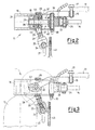
- Figure 2 is a first enlarged side elevation, with some elements shown in partial section, of a gripper closed about a container;
- Figure 3 is a second enlarged side elevation, with some elements shown in partial section, of the gripper of Figure 2 closed about a container;
- Figure 4 is an enlarged plan view from above showing an open gripper in partial section; and
- Figure 5 is a plan view from above showing the gripper of Figure 4 when inverted and closed.
-
- With reference to Figure 1, this shows a plurality of
container grippers 11, formed in accordance with the invention, in particular forbottles 12 shown in Figure 3. Thegrippers 11 are arranged on a carousel, only partly shown at 13, of a manipulating machine for bottles or similar containers. - The
carousel 13 is rotated by a drive (not shown). In this manner thecarousel 13 carries thegrippers 11, or parts of them, one after another into engagement with acam 14 which opens them to grasp the neck of thebottle 12 and/or releases them after the bottle has been grasped. - From the figures it can be seen that each
gripper 11 comprises essentially a support structure internally carrying a pair ofarms 16 driven to rotate between a closed rest position in which they face each other, and an open position in which they are withdrawn from each other. - The structure comprises a
U-shaped bracket 15 which can be fixed in an intermediate region to thecarousel 13 bybolts 17, between its open ends there being positioned ablock 18. Via itscylindrical ends 19 of smaller cross-section, theblock 18 can rotate about saidU bracket 15. This is made possible by inserting thecylindrical ends 19 intosleeves 20 inserted intoholes 21 in the free ends of thebracket 15. The parts are fixed together by abolt 22 passing freely through a hole in thesleeve 20, such as to enable theblock 18 to rotate. - This rotation is used to invert the
bottle 12 when necessary, by turning it through 180° by rotating theblock 18 within thesupport bracket 15. Asuitable shaft 23, fixed to theblock 18 and projecting from it, cooperates with anendless rod 24 fixed to anextension 27 of the machine structure and acting as a guide for the rotation of theblock 18. Theendless rod 24 surrounds the carousel and, by following a certain sinusoidal pattern, causes the movement of theshaft 23. - This latter engages the
rod 24 via itsterminal fork portion 25, which is maintained in permanent contact by cooperation with aspring 26. - The
arms 16 are rotatable by being pivoted by pairs of pivotingbolts 28 located on opposite sides of therotatable block 18 and only partially inserted into it in dead holes (not shown). Eacharm 16 is of box form with a U cross-section andcentral lugs 44 for locating saidbolts 28. A first end of thearms 16 carries a profiledportion 29 extending towards the facing arm and arranged to receive pads (not shown). In this manner pads of different sizes can be used, to make the gripper adaptable to bottles orcontainers 12 having different sized gripping regions. In an intermediate portion of thearms 16, between thecentral lugs 44, there are providedlateral slots 42 through which thesleeves 20 pass, together with thecylindrical ends 19 which rotatably support theblock 18. Theslots 42 allow the arms to open, and which would otherwise become locked as soon as they are rotated. Connectingrods 31 are pivoted at a first end to the second end of thearms 16 at 30, and are hinged together at their other end by apivot 32. One of the connectingrods 31 extends into a right-angled lever 33 carrying anidle wheel 34 arranged to interact with the said fixedcam 14 positioned in a localized region of the manipulating machine. In the illustrated advantageous arrangement the right-angled lever 33 is in the gripper rest position aligned with thearms 16, the connectingrods 31 being perpendicular to it. The right-angled lever 33 is positioned at about 90° to the connectingrods 31. - The right-
angled lever 33 also carries a travel-limitingappendix 35 which acts as a stop for its rotation by abutting against the outside of thearm 16. The position of thestop appendix 35 can also be adjusted to a certain extent by ascrew 36 which varies the abutment position. - The
pivot 32 is central between the sides of theU bracket 15, to it there also being fixed the end of apin 37 which is inserted through abush 38 inserted into aseat 39 provided in theblock 18. Aspring 41 interacts between aflange 40 rigid with the head of thepin 37, and an outwardlyopen seat 45 provided for the spring and and coaxial with theseat 39 for thebush 38. Thespring 41 usually tends to urge thepin 37 at least partly away from itsseat 45 or out of theseat 39 orbush 38. In this manner it closes thearms 16 of the gripper of the invention. - It should be noted that the gripper of the invention opens symmetrically, although being controlled by a right-
angled lever 33 acting directly on only one connectingrod 31. This is achieved by the interaction of thewheel 34 and thefixed cam 14, which rotates the right-angled lever 33. This causes the respective connectingrod 31 to rotate towards the interior of theU bracket 15, resulting in opening of therespective arm 16. However, at the same time thecentral pivot 32 also rotates the second connectingrod 31 involved with this pivot, to also rotate thesecond arm 16. The presence of thepin 37 perfectly correlates this simultaneous movement of thearms 16, which rotate about the pairs ofbolts 28 acting as rotation pins. Maximum opening of the two arms is determined by theflange 40 of thepin 37, which as this retracts into itsseat 39 abuts against thebush 38. - Both the
seat 45 for thespring 41, coaxial with the seat for thebush 38, and other elements of the gripper are open outwards to enable them to be cleaned. Generally there is therefore no element of the gripper of the invention which cannot be reached during cleaning. - It should be noted that the opening of the gripper is determined by an external element, namely the cam, which acts on an opening mechanism which is totally internal and incorporated into the moving part of the gripper. In this respect, it should be noted that the
block 18 is rotatable about thesleeves 20 and about thecylindrical ends 19 which support it. The reason for this is to be able to also invert the bottle to enable it to be rinsed and/or sterilized by for example asuitable nozzle 43 provided in the machine. - The provision of only one right-
angled lever 33 to open the entire gripper by interacting with thecam 14 results in resolution of the forces acting on the gripper into forces normal to the axis of thepin 37 and tangential forces, with lesser wear of the interacting parts. - Moreover this particular uneven arrangement of the operating right-
angled lever 33 enables the gripper to be mounted either as a right-hand or left-hand gripper without any problem. - The geometry involved in arranging the various parts makes the gripper of the invention very compact and suitable for machines of small overall dimensions. In particular, this gripper compactness makes it possible to construct machines having a very small distance between one gripper and the next.
- The presence of profiled portions on the gripper arms enables pads of various types to be mounted, making it possible to manipulate bottles with different diameter gripping regions.
Claims (10)
- A container gripper, in particular for bottles, which is positionable on a movable part (13) of a manipulating machine for bottles or similar containers (12), and comprises a support structure (15, 18) internally carrying a pair of arms (16) driven to rotate between a closed rest position in which they face each other to retain said container, and an open position in which they are withdrawn from each other to release said container, characterised in that said support structure comprises a U-shaped bracket (15) supporting a block (18) rotatable about said bracket, said arms (16) being pivoted to said block (18) and carrying, pivoted to the opposite end to their gripping end, a pair of connecting rods (31) for rotating the arms, one of said connecting rods extending into a right-angled lever (33) which can engage a cam (14) fixed relative to said movable part (13) of the manipulating machine and positioned in a localized region, said connecting rods (31) being pivoted at their other ends to a pin (37) slidable within a seat (39) in said block (18) by way of an interposed elastic element (41) which when at rest maintains said arms in their closed position.
- A gripper as claimed in claim 1, characterised in that when said gripper is in its rest position, said right-angled lever (33) is aligned with said arms (16), whereas said connecting rods (31) are perpendicular to them.
- A gripper as claimed in claim 1, characterised in that said right-angled lever (33) is positioned at about 90° to said connecting rod (31) from which it extends.
- A gripper as claimed in claim 1, characterised in that from said right-angled lever (33) there extends a travel-limiting appendix (35) which determines the closed position of said arms (16).
- A gripper as claimed in claim 1, characterised in that said elastic element (41) is a spring which acts between a flange (40) rigid with a head of said pin (37), and an outwardly open seat (45) coaxial with said seat (39) in which said pin (37) slides within a bush (38).
- A gripper as claimed in claim 1, characterised in that said block (18) is rotatable about said bracket (15) via its opposing cylindrical ends (19), which are inserted into sleeves (20) inserted in holes (21) in the free ends of said bracket (15), said parts (19, 20, 21) being fixable together by a bolt (22) which passes freely through a central hole in said sleeve (20) to enable said block to rotate.
- A gripper as claimed in claim 1, characterised in that said arms (16) are pivoted to said block (18) by pairs of pivoting bolts (28) which are inserted only partially into it from opposite sides.
- A gripper as claimed in claim 1, characterised in that each of said arms (16) is of box form with a U cross-section and central lugs (44) for locating said pivoting bolts (28).
- A gripper as claimed in claim 1, characterised in that from said block (18) there extends a shaft (23) which projects to cooperate with an endless profiled rod (24) fixed to a fixed part of the machine to act as a guide for the 180° rotational movement of said block (18).
- A gripper as claimed in claim 1, characterised in that said pin (37) is slidable within a bush (38) positioned in said seat (39) in said block (18).
Applications Claiming Priority (2)
| Application Number | Priority Date | Filing Date | Title |
|---|---|---|---|
| ITMI970076 | 1997-01-16 | ||
| IT97MI000076A IT1289906B1 (en) | 1997-01-16 | 1997-01-16 | GRIPPER TO GRAB CONTAINERS SUCH AS PARTICULAR BOTTLES |
Publications (2)
| Publication Number | Publication Date |
|---|---|
| EP0854102A1 EP0854102A1 (en) | 1998-07-22 |
| EP0854102B1 true EP0854102B1 (en) | 2001-08-01 |
Family
ID=11375638
Family Applications (1)
| Application Number | Title | Priority Date | Filing Date |
|---|---|---|---|
| EP98200048A Expired - Lifetime EP0854102B1 (en) | 1997-01-16 | 1998-01-09 | Container gripper, in particular for bottles |
Country Status (7)
| Country | Link |
|---|---|
| US (1) | US6079541A (en) |
| EP (1) | EP0854102B1 (en) |
| AR (1) | AR011423A1 (en) |
| AU (1) | AU730116B2 (en) |
| DE (1) | DE69801239T2 (en) |
| ES (1) | ES2159913T3 (en) |
| IT (1) | IT1289906B1 (en) |
Cited By (1)
| Publication number | Priority date | Publication date | Assignee | Title |
|---|---|---|---|---|
| EP2295352A2 (en) | 2009-09-11 | 2011-03-16 | Krones AG | Gripping unit for holding and moving items |
Families Citing this family (63)
| Publication number | Priority date | Publication date | Assignee | Title |
|---|---|---|---|---|
| DE19816239A1 (en) * | 1998-04-11 | 1999-10-14 | Krones Ag | Device for introducing and / or discharging containers into or from a treatment room |
| DE19919434A1 (en) * | 1999-04-29 | 2000-11-02 | Schuler Pressen Gmbh & Co | Part transfer facility |
| US6287055B1 (en) * | 1999-06-22 | 2001-09-11 | Ouellette Machinery Systems, Inc. | Air conveyor neck ring change-over with vertical pivot section |
| IT248463Y1 (en) * | 1999-09-30 | 2003-02-04 | Sasib Spa | DEFORMATION CLAMP IN PARTICULAR FOR RINSING MACHINE |
| FR2824542B3 (en) * | 2001-05-09 | 2003-06-13 | Rosebud Consulting Ltd | CONTAINER GRIPPER AND METHOD OF TRANSPORTING THE SAME |
| DE10130533A1 (en) * | 2001-06-25 | 2003-01-09 | Pactec Verpackungsmaschinen Fa | Method and device for assembling and packaging small items |
| FR2827044B1 (en) * | 2001-07-04 | 2004-09-10 | Perrier Sa | METHOD AND MACHINE FOR PROVIDING CONTAINERS TO BE RUNNED IN FRONT OF A FOREIGN BODY DETECTION STATION |
| ITPR20010050A1 (en) * | 2001-07-31 | 2003-01-31 | Sig Simonazzi Beverage S P A | CLAMP, IN PARTICULAR FOR HOLDING CONTAINERS. |
| DE10146490A1 (en) * | 2001-09-20 | 2003-04-24 | Hensen Packaging Concept Gmbh | Bag removal device |
| JP4079368B2 (en) * | 2003-08-19 | 2008-04-23 | 東洋自動機株式会社 | Spout or spouted bag supply device |
| US7021453B2 (en) * | 2003-11-13 | 2006-04-04 | Hartness International, Inc. | Conveyor with gear mechanism gripper and related conveyor link |
| US7055676B2 (en) * | 2003-11-13 | 2006-06-06 | Hartness International, Inc. | Conveyor with movable gripper and related conveyor link |
| US7216758B2 (en) | 2003-11-13 | 2007-05-15 | Hartness International, Inc. | Conveyor with opposed spring-loaded grippers, and related conveyor link |
| US7264113B2 (en) | 2003-11-13 | 2007-09-04 | Hartness International, Inc. | Pivotable conveyor and link |
| US7055677B2 (en) * | 2003-11-13 | 2006-06-06 | Hartness International, Inc. | Conveyor with movable grippers, and related conveyor link |
| US7036658B2 (en) * | 2003-11-13 | 2006-05-02 | Hartness International, Inc. | Gripper conveyor with clear conveying path and related conveyor link |
| US7261199B2 (en) | 2004-06-29 | 2007-08-28 | Hartness International, Inc. | Neck gripping conveyor and link, and related rotary filler and system |
| US7278531B2 (en) | 2004-06-29 | 2007-10-09 | Hartness International, Inc. | Flexible conveyor and connection elements |
| US7207434B2 (en) | 2003-11-13 | 2007-04-24 | Hartness International, Inc. | Conveyor with center-actuatable gripper, and related conveyor link |
| US7810629B2 (en) * | 2004-02-02 | 2010-10-12 | Krones Ag | Device for dynamic storage of objects |
| US7331156B2 (en) | 2004-06-29 | 2008-02-19 | Hartness International, Inc. | System for securely conveying articles and related components |
| US7299832B2 (en) | 2004-06-29 | 2007-11-27 | Hartness International, Inc. | Rotary filling machine and related components, and related method |
| DE102004034306B3 (en) * | 2004-07-15 | 2006-04-13 | Krones Ag | Gripper for container and container handling machine |
| US7185753B2 (en) | 2004-09-28 | 2007-03-06 | Hartness International, Inc. | Shuttle conveyor |
| DE202004016069U1 (en) | 2004-10-16 | 2005-12-01 | Krones Ag | Device for buffering objects |
| DE202005013552U1 (en) | 2005-08-27 | 2005-11-03 | Krones Ag | Dynamic storage for buffering and transporting empty bottle, has lower deflection pulleys rotating in essentially horizontal planes and connected with vertical loops by curved guides for conveyor chain |
| DE102006008123A1 (en) * | 2006-02-20 | 2007-08-23 | Krones Ag | Dynamic conveyor holding zone, for items being carried, has two conveyor paths moving in opposite directions with a transfer unit to move them from one to the other and a control unit linked to sensors |
| EP1832385B1 (en) * | 2006-03-07 | 2008-10-22 | PackSys Global (Switzerland) Ltd. | Apparatus for supplying workpieces to a rotary table |
| DE102006012148A1 (en) * | 2006-03-16 | 2007-09-20 | Krones Ag | funding |
| US20070221072A1 (en) * | 2006-03-23 | 2007-09-27 | Dennis Caprara | Systems and methods for automatically trimming and coring romaine lettuce and other harvested products |
| US7922226B2 (en) * | 2006-07-10 | 2011-04-12 | Goss International Americas, Inc. | Compensating gripper with independent gripper adjustment |
| DE102006035109A1 (en) * | 2006-07-29 | 2008-01-31 | Krones Ag | Conveyor device for use in bottle handling device, has conveyors separated from each other and connected with buffer over transferring points, where intermediate conveyor bypasses buffer |
| DE102008022848B4 (en) * | 2008-05-08 | 2012-03-29 | Khs Gmbh | PET bottle grippers |
| DE102008055620A1 (en) * | 2008-11-03 | 2010-05-20 | Khs Ag | Device for gripping PET bottles with a pushing body |
| US20110036688A1 (en) * | 2009-08-13 | 2011-02-17 | Yen-Yu Chen | Conveyor having a grip unit |
| DE102010009364B4 (en) * | 2010-02-25 | 2017-05-18 | Khs Gmbh | Bottle clamp with lock |
| IT1399982B1 (en) * | 2010-04-30 | 2013-05-09 | Arol Spa | SOCKET DEVICE FOR AUTOMATIC CAPPING MACHINES |
| CN102114485A (en) * | 2010-09-27 | 2011-07-06 | 楚天科技股份有限公司 | Vertical bottle washing machine turntable assembly with sealing structure |
| US8302640B2 (en) * | 2012-01-09 | 2012-11-06 | Safe-T-Med, Llc | Medical vial capture and retention system and method |
| DE102012017048B4 (en) * | 2012-08-29 | 2016-09-15 | Khs Gmbh | Container and transport device with self-adaptive gripping elements and method for cross-transport of containers to a treatment and transport device |
| USD734793S1 (en) * | 2014-02-01 | 2015-07-21 | John M. Leslie | Container gripper |
| DE102014116004B3 (en) * | 2014-11-03 | 2016-02-18 | Khs Gmbh | Container clamp for holding and guiding containers |
| JP6479622B2 (en) * | 2015-10-07 | 2019-03-06 | 東洋自動機株式会社 | Gripper device |
| CN105640892A (en) * | 2016-03-30 | 2016-06-08 | 成都中牧生物药业有限公司 | Preparation technology of tylosin tartrate premix based on uniform mixing effect improvement |
| CN105689349B (en) * | 2016-03-30 | 2018-01-30 | 成都中牧生物药业有限公司 | Reagent bottle wiper mechanism with buffer structure |
| CN105665393B (en) * | 2016-03-30 | 2018-01-30 | 成都中牧生物药业有限公司 | Processing system based on protection reagent bottle |
| CN105859808A (en) * | 2016-03-30 | 2016-08-17 | 成都中牧生物药业有限公司 | Preparation process for tylosin tartrate for injection capable of avoiding influence on drug natures of crude drugs |
| CN105853362A (en) * | 2016-03-30 | 2016-08-17 | 成都中牧生物药业有限公司 | Production method of tylosin tartrate for injection |
| CN105853363A (en) * | 2016-03-30 | 2016-08-17 | 成都中牧生物药业有限公司 | Preparation method of tylosin tartrate premix |
| CN105642629B (en) * | 2016-03-30 | 2018-01-30 | 成都中牧生物药业有限公司 | Injection reagent bottle wiper mechanism |
| CN105919940A (en) * | 2016-04-19 | 2016-09-07 | 成都中牧生物药业有限公司 | Preparation process of premix of tylosin tartrate |
| DE102016123640B3 (en) | 2016-12-07 | 2018-03-29 | Khs Gmbh | Gripper for container transport |
| CN107487493A (en) * | 2017-06-30 | 2017-12-19 | 中山诺顿科研技术服务有限公司 | Column product packaging and cleaning device |
| CN107601417B (en) * | 2017-08-31 | 2020-06-09 | 上海孚烜自动化科技有限公司 | Cleaning device for quantitative filling machine for liquid electronic chemicals |
| IT201800003295A1 (en) * | 2018-03-06 | 2019-09-06 | Smi Spa | Container handling device equipped with controlled opening grippers |
| CN109132459B (en) * | 2018-10-29 | 2024-04-05 | 长沙开元仪器有限公司 | Bottle feeding device for coal sample bottles |
| CN109573467B (en) * | 2019-01-04 | 2020-06-05 | 石思思 | A log conveying mechanism for wood processing |
| DE102019206441A1 (en) * | 2019-05-06 | 2020-11-12 | Bausch + Ströbel Maschinenfabrik Ilshofen GmbH + Co. KG | Syringe removal pincer wheel |
| US11224974B2 (en) * | 2020-01-15 | 2022-01-18 | Amtig Engineering Solutions, Llc | Bottle gripping assembly |
| IT202000005257A1 (en) * | 2020-03-11 | 2021-09-11 | Aea Srl | GRIPPING DEVICE |
| IT202100029057A1 (en) * | 2021-11-17 | 2023-05-17 | Gd Spa | Conveyor for the transport of assembled or semi-assembled cartridges for electronic cigarettes |
| CN117585448B (en) * | 2024-01-18 | 2024-04-05 | 常州市马劲机电设备有限公司 | Pipe conveying device |
| CN119037818B (en) * | 2024-08-07 | 2026-03-06 | 南京派诺思科学仪器有限公司 | Full-automatic solution split charging and sealing machine |
Family Cites Families (11)
| Publication number | Priority date | Publication date | Assignee | Title |
|---|---|---|---|---|
| US3570647A (en) * | 1969-06-13 | 1971-03-16 | Corning Glass Works | Loading apparatus |
| US3881607A (en) * | 1971-11-26 | 1975-05-06 | Gerity Schultz Corp | Transfer apparatus |
| US3944058A (en) * | 1973-04-19 | 1976-03-16 | Indian Head Inc. | Bottle conveyor system including adjustable height continuous belt conveyor and positive lock spray shielded rotatable bottle carrier |
| DE2615007A1 (en) * | 1976-04-07 | 1977-10-20 | Thyssen Plastik Maschinen Gmbh | Handling unit for moving plastics pipes - uses gripper attached to support plate actuated by rod system guided by curved plate |
| US4183428A (en) * | 1978-02-21 | 1980-01-15 | A-T-O Inc. | Mounting bar and gripper jaw assembly |
| IT1141837B (en) * | 1980-09-05 | 1986-10-08 | M E C I Di Bianchini & Marchin | IMPROVEMENTS TO AN AUTOMATIC RINSING MACHINE |
| US4468277A (en) * | 1983-07-05 | 1984-08-28 | Owens-Illinois, Inc. | Fixed jaw means for holding and rotating containers traveling around a turret periphery |
| DE3819126A1 (en) * | 1988-06-04 | 1990-02-08 | Bosch Gmbh Robert | DEVICE FOR CLEANING CONTAINERS |
| FR2660917B1 (en) * | 1990-04-11 | 1992-11-20 | Perrier Rene | GRIPPERS AND MACHINE FOR PROCESSING OBJECTS, PARTICULARLY BOTTLES, THUS EQUIPPED. |
| EP0743267B1 (en) * | 1995-05-13 | 1999-02-03 | Hermann Kronseder | Star coneyor for vessels |
| US5711411A (en) * | 1995-11-13 | 1998-01-27 | Lever Brothers Company, Division Of Conopco, Inc. | Quick changeover filling, centering bracket |
-
1997
- 1997-01-16 IT IT97MI000076A patent/IT1289906B1/en active IP Right Grant
-
1998
- 1998-01-08 US US09/002,407 patent/US6079541A/en not_active Expired - Fee Related
- 1998-01-09 EP EP98200048A patent/EP0854102B1/en not_active Expired - Lifetime
- 1998-01-09 ES ES98200048T patent/ES2159913T3/en not_active Expired - Lifetime
- 1998-01-09 DE DE69801239T patent/DE69801239T2/en not_active Expired - Lifetime
- 1998-01-14 AU AU52062/98A patent/AU730116B2/en not_active Ceased
- 1998-01-16 AR ARP980100187A patent/AR011423A1/en unknown
Cited By (3)
| Publication number | Priority date | Publication date | Assignee | Title |
|---|---|---|---|---|
| EP2295352A2 (en) | 2009-09-11 | 2011-03-16 | Krones AG | Gripping unit for holding and moving items |
| DE102009043984A1 (en) | 2009-09-11 | 2011-03-17 | Krones Ag | Gripping unit for holding and moving articles |
| US8556062B2 (en) | 2009-09-11 | 2013-10-15 | Krones Ag | Gripper unit for supporting and transporting articles |
Also Published As
| Publication number | Publication date |
|---|---|
| DE69801239D1 (en) | 2001-09-06 |
| EP0854102A1 (en) | 1998-07-22 |
| AU5206298A (en) | 1998-07-23 |
| IT1289906B1 (en) | 1998-10-19 |
| DE69801239T2 (en) | 2002-05-02 |
| ES2159913T3 (en) | 2001-10-16 |
| AU730116B2 (en) | 2001-02-22 |
| AR011423A1 (en) | 2000-08-16 |
| US6079541A (en) | 2000-06-27 |
| ITMI970076A1 (en) | 1998-07-16 |
Similar Documents
| Publication | Publication Date | Title |
|---|---|---|
| EP0854102B1 (en) | Container gripper, in particular for bottles | |
| EP0577569B1 (en) | Pliers with movable jaws for gripping bottles or the like for mounting preferably on an automatic rinsing-sterilizing machine | |
| EP2248759B1 (en) | Machine for treating containers, in particular in a plant for bottling food products | |
| EP2186759B1 (en) | Apparatus for transferring containers | |
| KR101465641B1 (en) | Product transport device | |
| HK1007547B (en) | Pliers with movable jaws for gripping bottles or the like for mounting preferably on an automatic rinsing-sterilizing machine | |
| CN110228703B (en) | Container handling device provided with a clamp opening on command | |
| US20040025909A1 (en) | Device for inverting a hollow body | |
| CN1132668A (en) | Ware cleaning machine | |
| EP0608823B1 (en) | Wrapping machine, particularly for food products such as sweets and similar | |
| US4395069A (en) | Pincers-type gripper for seizing objects and gripping head equipped with such grippers | |
| US20080038099A1 (en) | Gripper for Containers and Container Handling Machine | |
| AU2005234728A1 (en) | Device for forming groups of products, for instance for automatic packaging machinery | |
| US20210130110A1 (en) | Gripping device as well as transport device for gripping, holding and guiding in particular bottle-like containers | |
| KR20010040743A (en) | Transfer device for hollow body comprising a neck | |
| EP0479558B1 (en) | Mold arm closing mechanism for an individual section machine | |
| US20110220463A1 (en) | Device for gripping pet bottles having a pusher body | |
| KR100189206B1 (en) | Device for controlling gripping action of plate-like object | |
| EP2653239B1 (en) | A gripper for retaining bottles | |
| EP0136046A1 (en) | Take-out mechanism for a glassware forming machine | |
| EP0367005A1 (en) | Apparatus for applying closures to containers | |
| US5187916A (en) | Gripper for plastic film automatic machine | |
| WO1999051514A1 (en) | Adjustable gripper for containers, in particular for a star conveyor | |
| CA2053968C (en) | Apparatus for applying closures to containers | |
| US4769971A (en) | Apparatus for introducing blister-type products and the like into boxes |
Legal Events
| Date | Code | Title | Description |
|---|---|---|---|
| PUAI | Public reference made under article 153(3) epc to a published international application that has entered the european phase |
Free format text: ORIGINAL CODE: 0009012 |
|
| AK | Designated contracting states |
Kind code of ref document: A1 Designated state(s): BE CH DE ES FR GB LI PT |
|
| AX | Request for extension of the european patent |
Free format text: AL;LT;LV;MK;RO;SI |
|
| 17P | Request for examination filed |
Effective date: 19981028 |
|
| AKX | Designation fees paid |
Free format text: BE CH DE ES FR GB LI PT |
|
| RBV | Designated contracting states (corrected) |
Designated state(s): BE CH DE ES FR GB LI PT |
|
| GRAG | Despatch of communication of intention to grant |
Free format text: ORIGINAL CODE: EPIDOS AGRA |
|
| 17Q | First examination report despatched |
Effective date: 20001215 |
|
| GRAG | Despatch of communication of intention to grant |
Free format text: ORIGINAL CODE: EPIDOS AGRA |
|
| GRAH | Despatch of communication of intention to grant a patent |
Free format text: ORIGINAL CODE: EPIDOS IGRA |
|
| GRAH | Despatch of communication of intention to grant a patent |
Free format text: ORIGINAL CODE: EPIDOS IGRA |
|
| RAP1 | Party data changed (applicant data changed or rights of an application transferred) |
Owner name: S.B.R. S.R.L. |
|
| GRAA | (expected) grant |
Free format text: ORIGINAL CODE: 0009210 |
|
| AK | Designated contracting states |
Kind code of ref document: B1 Designated state(s): BE CH DE ES FR GB LI PT |
|
| REG | Reference to a national code |
Ref country code: CH Ref legal event code: EP |
|
| REF | Corresponds to: |
Ref document number: 69801239 Country of ref document: DE Date of ref document: 20010906 |
|
| REG | Reference to a national code |
Ref country code: CH Ref legal event code: NV Representative=s name: AMMANN PATENTANWAELTE AG BERN |
|
| REG | Reference to a national code |
Ref country code: ES Ref legal event code: FG2A Ref document number: 2159913 Country of ref document: ES Kind code of ref document: T3 |
|
| PG25 | Lapsed in a contracting state [announced via postgrant information from national office to epo] |
Ref country code: PT Free format text: LAPSE BECAUSE OF FAILURE TO SUBMIT A TRANSLATION OF THE DESCRIPTION OR TO PAY THE FEE WITHIN THE PRESCRIBED TIME-LIMIT Effective date: 20011105 |
|
| ET | Fr: translation filed | ||
| REG | Reference to a national code |
Ref country code: GB Ref legal event code: IF02 |
|
| PLBE | No opposition filed within time limit |
Free format text: ORIGINAL CODE: 0009261 |
|
| STAA | Information on the status of an ep patent application or granted ep patent |
Free format text: STATUS: NO OPPOSITION FILED WITHIN TIME LIMIT |
|
| 26N | No opposition filed | ||
| PGFP | Annual fee paid to national office [announced via postgrant information from national office to epo] |
Ref country code: GB Payment date: 20030108 Year of fee payment: 6 |
|
| PGFP | Annual fee paid to national office [announced via postgrant information from national office to epo] |
Ref country code: CH Payment date: 20030116 Year of fee payment: 6 |
|
| PGFP | Annual fee paid to national office [announced via postgrant information from national office to epo] |
Ref country code: BE Payment date: 20030313 Year of fee payment: 6 |
|
| PG25 | Lapsed in a contracting state [announced via postgrant information from national office to epo] |
Ref country code: GB Free format text: LAPSE BECAUSE OF NON-PAYMENT OF DUE FEES Effective date: 20040109 |
|
| PG25 | Lapsed in a contracting state [announced via postgrant information from national office to epo] |
Ref country code: LI Free format text: LAPSE BECAUSE OF NON-PAYMENT OF DUE FEES Effective date: 20040131 Ref country code: CH Free format text: LAPSE BECAUSE OF NON-PAYMENT OF DUE FEES Effective date: 20040131 Ref country code: BE Free format text: LAPSE BECAUSE OF NON-PAYMENT OF DUE FEES Effective date: 20040131 |
|
| BERE | Be: lapsed |
Owner name: *SBR S.R.L. Effective date: 20040131 |
|
| GBPC | Gb: european patent ceased through non-payment of renewal fee |
Effective date: 20040109 |
|
| REG | Reference to a national code |
Ref country code: CH Ref legal event code: PL |
|
| PGFP | Annual fee paid to national office [announced via postgrant information from national office to epo] |
Ref country code: DE Payment date: 20110121 Year of fee payment: 14 Ref country code: FR Payment date: 20110202 Year of fee payment: 14 |
|
| PGFP | Annual fee paid to national office [announced via postgrant information from national office to epo] |
Ref country code: ES Payment date: 20110125 Year of fee payment: 14 |
|
| REG | Reference to a national code |
Ref country code: FR Ref legal event code: ST Effective date: 20120928 |
|
| PG25 | Lapsed in a contracting state [announced via postgrant information from national office to epo] |
Ref country code: DE Free format text: LAPSE BECAUSE OF NON-PAYMENT OF DUE FEES Effective date: 20120801 |
|
| REG | Reference to a national code |
Ref country code: DE Ref legal event code: R119 Ref document number: 69801239 Country of ref document: DE Effective date: 20120801 |
|
| PG25 | Lapsed in a contracting state [announced via postgrant information from national office to epo] |
Ref country code: FR Free format text: LAPSE BECAUSE OF NON-PAYMENT OF DUE FEES Effective date: 20120131 |
|
| REG | Reference to a national code |
Ref country code: ES Ref legal event code: FD2A Effective date: 20130708 |
|
| PG25 | Lapsed in a contracting state [announced via postgrant information from national office to epo] |
Ref country code: ES Free format text: LAPSE BECAUSE OF NON-PAYMENT OF DUE FEES Effective date: 20120110 |