EP0852095B1 - Procedure and system for ensuring emergency communication - Google Patents
Procedure and system for ensuring emergency communication Download PDFInfo
- Publication number
- EP0852095B1 EP0852095B1 EP97927212A EP97927212A EP0852095B1 EP 0852095 B1 EP0852095 B1 EP 0852095B1 EP 97927212 A EP97927212 A EP 97927212A EP 97927212 A EP97927212 A EP 97927212A EP 0852095 B1 EP0852095 B1 EP 0852095B1
- Authority
- EP
- European Patent Office
- Prior art keywords
- emergency
- access node
- interface
- connection
- procedure
- Prior art date
- Legal status (The legal status is an assumption and is not a legal conclusion. Google has not performed a legal analysis and makes no representation as to the accuracy of the status listed.)
- Expired - Lifetime
Links
- 238000004891 communication Methods 0.000 title claims description 39
- 238000000034 method Methods 0.000 title claims description 28
- 230000011664 signaling Effects 0.000 claims description 17
- 238000012360 testing method Methods 0.000 claims description 5
- 238000012544 monitoring process Methods 0.000 claims description 4
- 230000005236 sound signal Effects 0.000 claims description 3
- 230000004913 activation Effects 0.000 description 2
- 230000008901 benefit Effects 0.000 description 2
- 230000005540 biological transmission Effects 0.000 description 2
- 230000008569 process Effects 0.000 description 2
- 238000012956 testing procedure Methods 0.000 description 2
- 238000012546 transfer Methods 0.000 description 2
- 230000009471 action Effects 0.000 description 1
- 230000006870 function Effects 0.000 description 1
- 238000009434 installation Methods 0.000 description 1
- 230000007257 malfunction Effects 0.000 description 1
- 230000002093 peripheral effect Effects 0.000 description 1
- 230000003068 static effect Effects 0.000 description 1
Images

Classifications
-
- H—ELECTRICITY
- H04—ELECTRIC COMMUNICATION TECHNIQUE
- H04M—TELEPHONIC COMMUNICATION
- H04M3/00—Automatic or semi-automatic exchanges
- H04M3/08—Indicating faults in circuits or apparatus
- H04M3/12—Marking faulty circuits "busy"; Enabling equipment to disengage itself from faulty circuits ; Using redundant circuits; Response of a circuit, apparatus or system to an error
-
- H—ELECTRICITY
- H04—ELECTRIC COMMUNICATION TECHNIQUE
- H04L—TRANSMISSION OF DIGITAL INFORMATION, e.g. TELEGRAPHIC COMMUNICATION
- H04L12/00—Data switching networks
- H04L12/50—Circuit switching systems, i.e. systems in which the path is physically permanent during the communication
- H04L12/52—Circuit switching systems, i.e. systems in which the path is physically permanent during the communication using time division techniques
-
- H—ELECTRICITY
- H04—ELECTRIC COMMUNICATION TECHNIQUE
- H04M—TELEPHONIC COMMUNICATION
- H04M3/00—Automatic or semi-automatic exchanges
- H04M3/42—Systems providing special services or facilities to subscribers
- H04M3/50—Centralised arrangements for answering calls; Centralised arrangements for recording messages for absent or busy subscribers ; Centralised arrangements for recording messages
- H04M3/51—Centralised call answering arrangements requiring operator intervention, e.g. call or contact centers for telemarketing
Definitions
- the present invention relates to data communication networks.
- the present invention relates to a procedure as defined in the preamble of claim 1 and to a system as defined in the preamble of claim 8 for ensuring emergency communication in an access node connected to a data communication network and having a number of subscriber lines or subscribers connected to it for the connection of terminal equipment to the data communication network.
- the present invention relates to a procedure for the testing of the emergency communication feature, as defined in the preamble of claim 6.
- V5.1 and V5.2 Open interfaces between an access network and a local exchange are defined in the ETSI (European Telecommunications and Standards Institute) standards of the ETS 300 324 and ETS 300 347 series.
- V5 interfaces enable subscribers belonging to a physically separate access network to be connected to a telephone exchange using a standard interface.
- a dynamic concentrator interface V5.2 consistent with the standards ETS 300 347-1 and 347-2, consists of one or more (1 - 16) PCM (Pulse Code Modulation) cables.
- PCM Pulse Code Modulation
- One PCM cable comprises 32 channels, each of which with a transfer speed of 64 kbit/s, i.e. 2048 kbit/s in all.
- the V5.2 interface supports analogue telephones as used in the public telephone network, digital, such as ISDN (Integrated Services Digital Network) basic and system connections as well as other analogue or digital terminal equipment based on semi-fixed connections.
- ISDN Integrated Services Digital Network
- a static multiplexer interface V5.1 consistent with the standards ETS 300 324-1 and 324-2, consists of one PCM cable with a transfer speed of 2048 kbit/s.
- the V5.1 interface supports the same subscriber types as the V5.2 interface, except for the ISDN system connection.
- the terminal equipment can be connected to the access ports of the access node.
- One or more V5 interfaces can be connected to an access node.
- the access ports are created in the V5 interface by linking an unambiguous address of each port with a given address of the V5 interface. In the local exchange, this address is created as a V5 subscriber.
- each access port has an address which is linked with a V5 address and uses a given time slot or given time slots for signalling to the local exchange.
- the purpose of a system for ensuring emergency communication is to make sure that calls to emergency numbers of subscribers connected to an access node can be set up even when the V5 interface between the access node and the exchange is out of order.
- the V5.1 and V5.2 standards contain no definition of systems for ensuring emergency communication in case of failure. In this situation, the problem is that, at present, all communication, including emergency communication, via a specific V5 interface of a given subscriber is hindered when the V5 interface fails.
- Document US-A-5142571 discloses a digital telephone set.
- the telephone set includes also an emergency analog circuit that is made active in an emergency instead of a digital telephone circuit so that the handset is connected to an analog transmission line.
- Document EP-A-337163 discloses a circuit arrangement in which a subscriber station is directly connected to a predeterined exchange line if a fault preventing normal switching operation occurs.
- Document EP-A-730389 discloses a method for the connection of V5.2 access networks to communication systems comprising non-redundant peripheral apparatus.
- the object of the present invention is to eliminate the problems described above.
- a specific object of the invention is to present an effective procedure for ensuring emergency communication in an access node in the event of a failure of the V5 interface used by a subscriber.
- a further object of the present invention is to present a feature currently missing in the access node that makes it possible to ensure subscribers' emergency communication as long as the access node is in operation.
- a number of terminal devices used by subscribers to set up connections over the data communication network are connected to the access node, preferably via subscriber cables.
- signalling consistent with the V5 standard is used in the connection between the access node and the telephone exchange, which is a standard V5 interface.
- an emergency line is created in the access node by using local operation control commands.
- the emergency line is generally created in conjunction with the installation and start-up of the access node.
- 'emergency line' means an access node subscriber line to which emergency communication is directed when the link between the access node and the local exchange is broken.
- Emergency communication is preferably controlled by using the internal group switch of the access node.
- at least one emergency number is created for the emergency line of the access node by using local access node commands.
- the status of the V5 interface used by the subscriber is monitored in the access node, and if, based on this monitoring, the V5 interface is found to be out of order, a predetermined connection setup mode is entered in which the connection is set up locally in the access node.
- a call from the terminal device to an emergency number is connected locally by means of the internal group switch of the access node to the emergency line.
- MML Man Machine Language
- the present invention has the advantage that, using the procedure of the invention, emergency communication of subscribers connected to an access node can be effectively and reliably guaranteed even in the event of a failure of the V5 interface used by the subscriber.
- the status of the V5 interface used by the subscriber i.e. information as to whether the interface is in working order or not
- a file used to store status data relating to each V5 interface i.e. data indicating failure and restoration of the control channel of the V5 interface.
- a failure situation in a V5 interface occurs when the signalling connection from the subscriber to the local exchange fails.
- the emergency line is connected via a permanent link to a location predetermined by the teleoperator, such as an exchange room, the teleoperator's customer service or the like.
- a permanent link can be provided from the emergency line to a mobile telephone, a pager or equivalent.
- service can be provided via the emergency line connected to the exchange room.
- the invention also relates to a procedure for testing the operation of emergency lines and/or emergency numbers created in an access node.
- the testing procedure is used to ensure that emergency communication via the access node really works.
- at least two emergency lines are provided in the access node, so that a connection to an emergency number can be set up from one of the emergency lines.
- the signalling programmes automatically perform a check to see whether the V5 access port calling an emergency number has a V5 address and whether the calling line has been created as an emergency line for failure situations. If it is established in the access node that the call setup message to an emergency number comes from an emergency line of the access node, then the access node will work in a manner corresponding to operation in a failure situation and the call is connected to the dialled emergency number.
- connection setup to the emergency line is successful, this is an indication that the emergency communication feature is operational.
- a connection can be set up from the emergency lines in both directions, in other words, first from the first emergency line to the second one and then from the second emergency line to the first one, thus making sure that both emergency lines are in working order.
- a further advantage of the checking procedure is that the emergency lines can be tested without interrupting normal telephone traffic through the access node.
- the access node comprises an emergency line for emergency communication created using the local operation control commands of the access node and an emergency number created using the local operation control commands of the access node, wherein calls to the emergency number are adapted to be connected to the emergency line.
- the access node of the invention comprises means, preferably an internal group switch within the access node, which group switch is preferably a fully digital, full-scale single-phase time-shared switch without rejection, adapted to direct calls made by subscribers to emergency numbers to the emergency line when the V5 interface used by the subscriber is out of order, and means connected to the emergency line adapted to set up a connection to a specified terminal device via the emergency line.
- group switch is preferably a fully digital, full-scale single-phase time-shared switch without rejection, adapted to direct calls made by subscribers to emergency numbers to the emergency line when the V5 interface used by the subscriber is out of order, and means connected to the emergency line adapted to set up a connection to a specified terminal device via the emergency line.
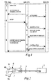
- Fig. 1 presents an example of the signalling in the case of a prior-art ISDN call over a V5 interface.
- LAPD signalling data link layer protocol in ISDN channel D
- the access node (AN) 3 activates the terminal device (step 2) and sends a message indicating activation of the terminal device to the telephone exchange (LE) 1 (step 3), using the control protocol.
- the terminal device 4c sends a SETUP message over channel D of the subscriber cable.
- the access node On receiving the SETUP message, the access node identifies (step 5) the corresponding V5 interface and the V5 subscriber address of the subscriber cable (which in fact is a third-layer address, L3 address, consistent with the OSI architecture (Open Systems Interconnection)) on the basis of the subscriber cable. Moreover, the access node adds a V5 header to the SETUP message and sends it via the Ds channel of the corresponding V5 interface to the telephone exchange 1. The LAPD signalling itself is passed as such over the V5 interface via the signalling channel reserved for the subscriber. Thus, the V5 interface software in the access node 3 does not interfere with the contents of messages in any way.
- the V5 interface software in the access node 3 does not interfere with the contents of messages in any way.
- the V5 header is removed (step 6) and the SETUP message is transmitted further to an ISDN call setup control stage, where it is terminated.
- the local exchange selects the V5 time slot to be used, and this information is given to the access node 3 together with the L3 address (step 7).
- the access node 3 identifies the subscriber cable on the basis of the L3 address received and, via its local group switch, connects (step 8) the B channel of the subscriber cable to the V5 interface time slot reserved for it. Further, the access node 3 sends (step 9) to the telephone exchange 1 a message confirming completion of the connection.
- the telephone exchange 1 sends the standard ISDN call control messages relating to call setup to the terminal device via the access node over the Ds channel reserved for the subscriber cable (step 10).
- the system presented in Fig. 2 comprises an access node 3 with a number of subscribers 4a, 4c connected to it.
- the access node 3 operates between an exchange 1 and the subscribers 4a, 4c and connects subscribers to a telephone exchange in a data communication network in the manner illustrated by Fig. 1.
- the access node 3 is connected via a V5.2 interface 5, which comprises 1 - 16 PCM cables (2 Mbit/s), to the exchange terminal (ET) 10 of the terminal exchange 1, which is provided with the functions required by the V5 interface.
- the access node can also be connected to the telephone exchange 1 via a V5.1 interface.
- the access node comprises at least one emergency line 6 created for emergency communication and connected to a specified terminal device via a connection preferably carried out by an operator.
- a number of emergency numbers are created in the access node 3. For each emergency number, preferably one or more emergency lines are created. Due to the requirements pertaining to the access node, generally no other numbers except emergency numbers are created in it.
- one emergency number at a time can be created, and for each emergency line 6, one to six emergency numbers can be created.
- the lines are given with a logical location number so that the command gives the access module number only once, because the series attribute of the emergency numbers in a preferred embodiment is limited to one access module. From the series attribute being limited to one access module it also automatically follows that all emergency lines under a given emergency number must be included in the same access module.
- it is possible to create a maximum of 20 emergency numbers for one emergency line yet the total number of emergency numbers is preferably not more than 20.
- the maximum length of an emergency number is 12 digits.
- an emergency number cannot be created as a normal subscriber line, and on the other hand a normal subscriber cannot be assigned a line created as an emergency line.
- the maximum number of emergency calls that can be active at the same time is 4, which depends on the number of emergency lines.
- the push-button dialling receiver of the access node limits the number of analogue emergency calls at the setup stage to 64. It must be noted, however, that if the subscriber uses pulse dialling, the push-button dialling receiver is released immediately at the beginning of the dialling, permitting a larger number of emergency calls at the setup stage. In the case of digital emergency calls, no push-button dialling receiver is needed.
- MB1PRB is a program used for the transmission of LAPD frames, which maintains specific information about the routing direction of signalling in each port and performs the connection of time slots in the access module.
- PRLPGM is an ISDN 2 nd -layer programme for access node failure situations, which monitors the condition of the Ds channel of the V5 interface and reports changes in the status of the interface.
- IS3PRS is an ISDN 2 nd -layer programme for access node failure situations, which allocates a module cable for an ISDN subscriber.
- CDNPRB takes care of actual call setup in emergency communication, connection and disconnection of the speech path, connection of messages and reservation and release of push-button dialling receivers.
- SWICOP is a programme controlling the local group switch 7 of the access node.
- ZASPRB takes care of analogue subscriber signalling.
- An outgoing ISDN (2B+D) emergency call in the event of a failure of the V5 interface used by the subscriber is as follows. When the subscriber picks up the headphone to call an emergency number, LAPD signalling (data link layer communication protocol in ISDN channel D) is started by the MP1PRB module. IS3PRB acknowledges the activation request. Next, 2-layer connection consistent with the OSI model is set up by means of the PRLPGM and IS3PRB modules.
- module IS3PRB checks that the required parameters are in:: order.
- the subscriber dials a number, it is analyzed by the appropriate programme to establish whether the subscriber is calling an emergency number existing in the access node concerned. If the call is found to be addressed to such an emergency number, then the call setup procedure is continued and the subscriber is given the necessary sound signals to indicate that the system is trying to set up a connection to the emergency number.
- the emergency number responds, i.e. when the called subscriber picks up the headphone or performs some other action to answer the calling subscriber's call attempt, a talking connection is set up.
- a call setup process as described above can also be carried out from an emergency line created in the access node by making a call from it to an emergency number. This makes it possible to test the emergency lines to make sure that the emergency lines and the access node control system for calls to local emergency numbers are in working order.
- the emergency line busy test, number analysis and call termination can be carried out in the access node in many known ways, as can the call setup process described above. It should be further noted that the example described above can also be applied to environments other than ISDN, e.g. an analogue environment.
Landscapes
- Engineering & Computer Science (AREA)
- Signal Processing (AREA)
- Business, Economics & Management (AREA)
- Marketing (AREA)
- Computer Networks & Wireless Communication (AREA)
- Telephonic Communication Services (AREA)
- Data Exchanges In Wide-Area Networks (AREA)
Applications Claiming Priority (3)
| Application Number | Priority Date | Filing Date | Title |
|---|---|---|---|
| FI962575 | 1996-06-20 | ||
| FI962575A FI103372B (fi) | 1996-06-20 | 1996-06-20 | Menetelmä ja järjestelmä hätäliikenteen varmistamiseksi |
| PCT/FI1997/000393 WO1997049231A1 (en) | 1996-06-20 | 1997-06-18 | Procedure and system for ensuring emergency communication |
Publications (2)
| Publication Number | Publication Date |
|---|---|
| EP0852095A1 EP0852095A1 (en) | 1998-07-08 |
| EP0852095B1 true EP0852095B1 (en) | 2005-04-20 |
Family
ID=8546258
Family Applications (1)
| Application Number | Title | Priority Date | Filing Date |
|---|---|---|---|
| EP97927212A Expired - Lifetime EP0852095B1 (en) | 1996-06-20 | 1997-06-18 | Procedure and system for ensuring emergency communication |
Country Status (9)
| Country | Link |
|---|---|
| US (1) | US6069948A (fi) |
| EP (1) | EP0852095B1 (fi) |
| JP (1) | JPH11511931A (fi) |
| CN (1) | CN1196854A (fi) |
| AU (1) | AU721259B2 (fi) |
| BR (1) | BR9702304A (fi) |
| DE (1) | DE69733056T2 (fi) |
| FI (1) | FI103372B (fi) |
| WO (1) | WO1997049231A1 (fi) |
Families Citing this family (14)
| Publication number | Priority date | Publication date | Assignee | Title |
|---|---|---|---|---|
| FI101847B1 (fi) * | 1996-09-19 | 1998-08-31 | Nokia Telecommunications Oy | Menetelmä tilaajatietokannan käsittelemiseksi puhelinkeskuksessa |
| FI964714A7 (fi) | 1996-11-26 | 1998-05-27 | Nokia Telecommunications Oy | Menetelmä hätäpuhelun varmistamiseksi langattomassa tilaajaverkkoympäristössä |
| FI103624B1 (fi) | 1997-03-18 | 1999-07-30 | Nokia Telecommunications Oy | Menetelmä merkinantokanavien toiminnan varmistamiseksi V5-liitännässä |
| FI104679B (fi) * | 1997-04-18 | 2000-04-14 | Nokia Networks Oy | Menetelmä hätäpuhelun muodostamiseksi langattomassa tilaajaverkossa |
| FI103461B (fi) * | 1997-07-03 | 1999-06-30 | Nokia Telecommunications Oy | Menetelmä dataliikenteen välittämiseksi tietoliikennejärjestelmässä |
| FI973312A7 (fi) * | 1997-08-12 | 1999-02-13 | Nokia Telecommunications Oy | Menetelmä tilaajan osoittamiseksi ketjutetussa V5-liitännässä |
| FI104455B (fi) * | 1997-10-01 | 2000-01-31 | Nokia Networks Oy | Menetelmä hätäliikenteen varmistamiseksi ketjutetussa V5-liitännässä |
| SE514589C2 (sv) * | 1998-06-12 | 2001-03-19 | Ericsson Telefon Ab L M | Hantering av nätverk |
| US7046287B2 (en) * | 1999-12-24 | 2006-05-16 | Nec Corporation | Portable information terminal equipped with camera |
| US7720458B2 (en) * | 2002-05-30 | 2010-05-18 | Lockheed Martin Corporation | Rapidly deployable emergency communications system and method |
| US7680252B2 (en) | 2004-11-08 | 2010-03-16 | Aztek Engineering, Inc. | Switch proxy for providing emergency stand alone service in remote access systems |
| US7953210B2 (en) | 2005-06-27 | 2011-05-31 | Aztek Engineering, Inc. | Switch proxy for providing emergency stand-alone service in remote access systems |
| CN101163171B (zh) * | 2006-10-13 | 2010-08-18 | 中兴通讯股份有限公司 | 一种基于接入网实现上行业务接口保护的方法 |
| EP3223546B1 (en) * | 2014-11-21 | 2020-02-12 | Huawei Technologies Co., Ltd. | Method and device for executing emergency call |
Family Cites Families (7)
| Publication number | Priority date | Publication date | Assignee | Title |
|---|---|---|---|---|
| DE3812666A1 (de) * | 1988-04-15 | 1989-11-02 | Siemens Ag | Schaltungsanordnung zur umschaltung einer vermittlungseinrichtung vom normalen vermittlungsbetrieb in einen notbetrieb und umgekehrt |
| US5142571A (en) * | 1988-10-19 | 1992-08-25 | Fujitsu Limited | Digital telephone set having an emergency switching function and communication system having the same |
| US5418776A (en) * | 1993-02-26 | 1995-05-23 | At&T Corp. | Emergency local switching |
| US5509065A (en) * | 1993-11-12 | 1996-04-16 | Teltrend Inc. | Dual span monitoring system for maintenance shelf control |
| DE19506961C1 (de) * | 1995-02-28 | 1996-10-17 | Siemens Ag | Verfahren zum Anschluß von Access-Networks mit V5.2-Schnittstellen an Kommunikationssysteme mit nichtredundanten peripheren Einrichtungen |
| DE19508081A1 (de) * | 1995-03-08 | 1996-09-12 | Sel Alcatel Ag | Verfahren zum Steuern eines Zugangsnetzes sowie Vermittlungsstelle und Zugangsnetz damit |
| EP0760563A1 (en) * | 1995-08-29 | 1997-03-05 | ALCATEL BELL Naamloze Vennootschap | Multiframe structure and handling protocol for a telecommunication network |
-
1996
- 1996-06-20 FI FI962575A patent/FI103372B/fi active IP Right Grant
-
1997
- 1997-06-18 CN CN97190746A patent/CN1196854A/zh active Pending
- 1997-06-18 EP EP97927212A patent/EP0852095B1/en not_active Expired - Lifetime
- 1997-06-18 DE DE69733056T patent/DE69733056T2/de not_active Expired - Fee Related
- 1997-06-18 US US09/011,694 patent/US6069948A/en not_active Expired - Lifetime
- 1997-06-18 AU AU31783/97A patent/AU721259B2/en not_active Ceased
- 1997-06-18 BR BR9702304A patent/BR9702304A/pt not_active Application Discontinuation
- 1997-06-18 WO PCT/FI1997/000393 patent/WO1997049231A1/en not_active Ceased
- 1997-06-18 JP JP10502395A patent/JPH11511931A/ja active Pending
Also Published As
| Publication number | Publication date |
|---|---|
| JPH11511931A (ja) | 1999-10-12 |
| EP0852095A1 (en) | 1998-07-08 |
| DE69733056D1 (de) | 2005-05-25 |
| BR9702304A (pt) | 1999-03-02 |
| AU3178397A (en) | 1998-01-07 |
| AU721259B2 (en) | 2000-06-29 |
| FI962575L (fi) | 1997-12-21 |
| FI103372B1 (fi) | 1999-06-15 |
| FI103372B (fi) | 1999-06-15 |
| DE69733056T2 (de) | 2006-03-09 |
| CN1196854A (zh) | 1998-10-21 |
| FI962575A0 (fi) | 1996-06-20 |
| US6069948A (en) | 2000-05-30 |
| WO1997049231A1 (en) | 1997-12-24 |
Similar Documents
| Publication | Publication Date | Title |
|---|---|---|
| US6370232B1 (en) | Procedure and system for ensuring emergency communication | |
| CA1331802C (en) | Modularly structured digital communications system having operations-oriented and security-oriented components | |
| US5903626A (en) | Diagnostic device for troubleshooting remote digital feature phones | |
| US6081591A (en) | Signaling network gateway device and method for use in a signaling network | |
| US5187732A (en) | Board-to-board test unit for a digital subscriber line | |
| EP0852095B1 (en) | Procedure and system for ensuring emergency communication | |
| US5450396A (en) | Communication system and a private branch exchange to be used in such a communication system | |
| US6370122B1 (en) | Method for monitoring and checking subscriber connections to ISDN | |
| AU2485799A (en) | Local switch | |
| US6467055B1 (en) | Test system for use with a communications network, and apparatus and method for testing digital data transfer within a communications network | |
| US6430283B1 (en) | Communication system consisting of at least two private branch exchanges with pbx team function | |
| EP0976253A1 (en) | Procedure for scanning or disconnecting a module line in a v5.2 access node | |
| CA2229863A1 (en) | Procedure and system for ensuring emergency communication | |
| KR100263381B1 (ko) | 교환기에 있어서의 v5.2 인터페이스 구현장치 | |
| JP2917965B2 (ja) | V5通信回線における遠隔局加入者装置試験方法 | |
| KR100270742B1 (ko) | 전전자교환기의원격가입자모듈에서의호처리장치및방법 | |
| US6762998B1 (en) | Access network system | |
| EP1021919A1 (en) | Procedure for ensuring emergency communication in a cascaded v5 interface | |
| JP3107401B2 (ja) | デジタル回線のモニタ方法 | |
| JP3624851B2 (ja) | リモート交換機の系切り替え方法及び交換機システム | |
| KR100237473B1 (ko) | 협대역 종합정보통신망에서 패킷 영구 가상채널 설정방법 | |
| KR0156844B1 (ko) | 전자식 간이 교환장치 및 사설교환 시스템에서의 비상중계 방법 | |
| JP3008720B2 (ja) | Isdn信号中継交換装置 | |
| AU9563898A (en) | Method and device in telecommunications network | |
| JPH01264430A (ja) | Isdnパケット交換方式 |
Legal Events
| Date | Code | Title | Description |
|---|---|---|---|
| PUAI | Public reference made under article 153(3) epc to a published international application that has entered the european phase |
Free format text: ORIGINAL CODE: 0009012 |
|
| 17P | Request for examination filed |
Effective date: 19980216 |
|
| AK | Designated contracting states |
Kind code of ref document: A1 Designated state(s): BE DE ES FR GB IT NL SE |
|
| RAP1 | Party data changed (applicant data changed or rights of an application transferred) |
Owner name: NOKIA NETWORKS OY |
|
| RAP1 | Party data changed (applicant data changed or rights of an application transferred) |
Owner name: NOKIA CORPORATION |
|
| 17Q | First examination report despatched |
Effective date: 20030911 |
|
| GRAP | Despatch of communication of intention to grant a patent |
Free format text: ORIGINAL CODE: EPIDOSNIGR1 |
|
| GRAS | Grant fee paid |
Free format text: ORIGINAL CODE: EPIDOSNIGR3 |
|
| GRAA | (expected) grant |
Free format text: ORIGINAL CODE: 0009210 |
|
| AK | Designated contracting states |
Kind code of ref document: B1 Designated state(s): BE DE ES FR GB IT NL SE |
|
| PG25 | Lapsed in a contracting state [announced via postgrant information from national office to epo] |
Ref country code: NL Free format text: LAPSE BECAUSE OF FAILURE TO SUBMIT A TRANSLATION OF THE DESCRIPTION OR TO PAY THE FEE WITHIN THE PRESCRIBED TIME-LIMIT Effective date: 20050420 Ref country code: IT Free format text: LAPSE BECAUSE OF FAILURE TO SUBMIT A TRANSLATION OF THE DESCRIPTION OR TO PAY THE FEE WITHIN THE PRESCRIBED TIME-LIMIT;WARNING: LAPSES OF ITALIAN PATENTS WITH EFFECTIVE DATE BEFORE 2007 MAY HAVE OCCURRED AT ANY TIME BEFORE 2007. THE CORRECT EFFECTIVE DATE MAY BE DIFFERENT FROM THE ONE RECORDED. Effective date: 20050420 Ref country code: BE Free format text: LAPSE BECAUSE OF FAILURE TO SUBMIT A TRANSLATION OF THE DESCRIPTION OR TO PAY THE FEE WITHIN THE PRESCRIBED TIME-LIMIT Effective date: 20050420 |
|
| REG | Reference to a national code |
Ref country code: GB Ref legal event code: FG4D |
|
| REF | Corresponds to: |
Ref document number: 69733056 Country of ref document: DE Date of ref document: 20050525 Kind code of ref document: P |
|
| PGFP | Annual fee paid to national office [announced via postgrant information from national office to epo] |
Ref country code: NL Payment date: 20050605 Year of fee payment: 9 |
|
| PGFP | Annual fee paid to national office [announced via postgrant information from national office to epo] |
Ref country code: GB Payment date: 20050615 Year of fee payment: 9 |
|
| PGFP | Annual fee paid to national office [announced via postgrant information from national office to epo] |
Ref country code: DE Payment date: 20050616 Year of fee payment: 9 |
|
| PG25 | Lapsed in a contracting state [announced via postgrant information from national office to epo] |
Ref country code: SE Free format text: LAPSE BECAUSE OF FAILURE TO SUBMIT A TRANSLATION OF THE DESCRIPTION OR TO PAY THE FEE WITHIN THE PRESCRIBED TIME-LIMIT Effective date: 20050720 |
|
| PG25 | Lapsed in a contracting state [announced via postgrant information from national office to epo] |
Ref country code: ES Free format text: LAPSE BECAUSE OF FAILURE TO SUBMIT A TRANSLATION OF THE DESCRIPTION OR TO PAY THE FEE WITHIN THE PRESCRIBED TIME-LIMIT Effective date: 20050731 |
|
| PGFP | Annual fee paid to national office [announced via postgrant information from national office to epo] |
Ref country code: BE Payment date: 20050810 Year of fee payment: 9 |
|
| NLV1 | Nl: lapsed or annulled due to failure to fulfill the requirements of art. 29p and 29m of the patents act | ||
| PLBE | No opposition filed within time limit |
Free format text: ORIGINAL CODE: 0009261 |
|
| STAA | Information on the status of an ep patent application or granted ep patent |
Free format text: STATUS: NO OPPOSITION FILED WITHIN TIME LIMIT |
|
| 26N | No opposition filed |
Effective date: 20060123 |
|
| EN | Fr: translation not filed | ||
| PG25 | Lapsed in a contracting state [announced via postgrant information from national office to epo] |
Ref country code: GB Free format text: LAPSE BECAUSE OF NON-PAYMENT OF DUE FEES Effective date: 20060618 |
|
| PG25 | Lapsed in a contracting state [announced via postgrant information from national office to epo] |
Ref country code: DE Free format text: LAPSE BECAUSE OF NON-PAYMENT OF DUE FEES Effective date: 20070103 |
|
| GBPC | Gb: european patent ceased through non-payment of renewal fee |
Effective date: 20060618 |
|
| PGFP | Annual fee paid to national office [announced via postgrant information from national office to epo] |
Ref country code: FR Payment date: 20070630 Year of fee payment: 11 |
|
| PG25 | Lapsed in a contracting state [announced via postgrant information from national office to epo] |
Ref country code: FR Free format text: LAPSE BECAUSE OF NON-PAYMENT OF DUE FEES Effective date: 20080629 |