EP0851778B1 - Peritoneal dialysis tube connection with dual disinfectant system - Google Patents
Peritoneal dialysis tube connection with dual disinfectant system Download PDFInfo
- Publication number
- EP0851778B1 EP0851778B1 EP97915041A EP97915041A EP0851778B1 EP 0851778 B1 EP0851778 B1 EP 0851778B1 EP 97915041 A EP97915041 A EP 97915041A EP 97915041 A EP97915041 A EP 97915041A EP 0851778 B1 EP0851778 B1 EP 0851778B1
- Authority
- EP
- European Patent Office
- Prior art keywords
- piece
- connector
- housing
- connection
- connector according
- Prior art date
- Legal status (The legal status is an assumption and is not a legal conclusion. Google has not performed a legal analysis and makes no representation as to the accuracy of the status listed.)
- Expired - Lifetime
Links
- 239000000645 desinfectant Substances 0.000 title claims abstract description 31
- 238000000502 dialysis Methods 0.000 title claims abstract description 21
- 230000009977 dual effect Effects 0.000 title description 3
- 239000012530 fluid Substances 0.000 claims abstract description 39
- 238000004891 communication Methods 0.000 claims description 15
- 230000037361 pathway Effects 0.000 claims description 8
- 238000010521 absorption reaction Methods 0.000 claims description 7
- 239000006260 foam Substances 0.000 claims description 6
- 210000003200 peritoneal cavity Anatomy 0.000 claims description 6
- 238000007789 sealing Methods 0.000 claims description 5
- 238000012546 transfer Methods 0.000 abstract description 32
- 238000000034 method Methods 0.000 abstract description 14
- 238000003287 bathing Methods 0.000 abstract 1
- 229920006395 saturated elastomer Polymers 0.000 abstract 1
- 230000008901 benefit Effects 0.000 description 12
- 230000000249 desinfective effect Effects 0.000 description 10
- 230000002745 absorbent Effects 0.000 description 8
- 239000002250 absorbent Substances 0.000 description 8
- 238000004659 sterilization and disinfection Methods 0.000 description 8
- 239000000463 material Substances 0.000 description 7
- CPKVUHPKYQGHMW-UHFFFAOYSA-N 1-ethenylpyrrolidin-2-one;molecular iodine Chemical compound II.C=CN1CCCC1=O CPKVUHPKYQGHMW-UHFFFAOYSA-N 0.000 description 2
- 239000011324 bead Substances 0.000 description 2
- 238000011109 contamination Methods 0.000 description 2
- 230000000994 depressogenic effect Effects 0.000 description 2
- 208000015181 infectious disease Diseases 0.000 description 2
- 239000007788 liquid Substances 0.000 description 2
- 210000004379 membrane Anatomy 0.000 description 2
- 239000012528 membrane Substances 0.000 description 2
- 206010034674 peritonitis Diseases 0.000 description 2
- 229920000153 Povidone-iodine Polymers 0.000 description 1
- 206010040047 Sepsis Diseases 0.000 description 1
- 241000295644 Staphylococcaceae Species 0.000 description 1
- 230000000845 anti-microbial effect Effects 0.000 description 1
- 239000004599 antimicrobial Substances 0.000 description 1
- 229940064804 betadine Drugs 0.000 description 1
- 239000000356 contaminant Substances 0.000 description 1
- 230000003247 decreasing effect Effects 0.000 description 1
- 230000036541 health Effects 0.000 description 1
- 238000007654 immersion Methods 0.000 description 1
- 238000010348 incorporation Methods 0.000 description 1
- 238000003780 insertion Methods 0.000 description 1
- 230000037431 insertion Effects 0.000 description 1
- 230000007794 irritation Effects 0.000 description 1
- 230000007246 mechanism Effects 0.000 description 1
- 244000052769 pathogen Species 0.000 description 1
- 230000035699 permeability Effects 0.000 description 1
- 229960001621 povidone-iodine Drugs 0.000 description 1
- 230000008844 regulatory mechanism Effects 0.000 description 1
- 238000009877 rendering Methods 0.000 description 1
- 239000003206 sterilizing agent Substances 0.000 description 1
- 239000000126 substance Substances 0.000 description 1
Images


Classifications
-
- A—HUMAN NECESSITIES
- A61—MEDICAL OR VETERINARY SCIENCE; HYGIENE
- A61M—DEVICES FOR INTRODUCING MEDIA INTO, OR ONTO, THE BODY; DEVICES FOR TRANSDUCING BODY MEDIA OR FOR TAKING MEDIA FROM THE BODY; DEVICES FOR PRODUCING OR ENDING SLEEP OR STUPOR
- A61M39/00—Tubes, tube connectors, tube couplings, valves, access sites or the like, specially adapted for medical use
- A61M39/10—Tube connectors; Tube couplings
- A61M39/16—Tube connectors; Tube couplings having provision for disinfection or sterilisation
- A61M39/162—Tube connectors; Tube couplings having provision for disinfection or sterilisation with antiseptic agent incorporated within the connector
-
- A—HUMAN NECESSITIES
- A61—MEDICAL OR VETERINARY SCIENCE; HYGIENE
- A61M—DEVICES FOR INTRODUCING MEDIA INTO, OR ONTO, THE BODY; DEVICES FOR TRANSDUCING BODY MEDIA OR FOR TAKING MEDIA FROM THE BODY; DEVICES FOR PRODUCING OR ENDING SLEEP OR STUPOR
- A61M1/00—Suction or pumping devices for medical purposes; Devices for carrying-off, for treatment of, or for carrying-over, body-liquids; Drainage systems
- A61M1/14—Dialysis systems; Artificial kidneys; Blood oxygenators ; Reciprocating systems for treatment of body fluids, e.g. single needle systems for hemofiltration or pheresis
- A61M1/28—Peritoneal dialysis ; Other peritoneal treatment, e.g. oxygenation
- A61M1/285—Catheters therefor
-
- A—HUMAN NECESSITIES
- A61—MEDICAL OR VETERINARY SCIENCE; HYGIENE
- A61M—DEVICES FOR INTRODUCING MEDIA INTO, OR ONTO, THE BODY; DEVICES FOR TRANSDUCING BODY MEDIA OR FOR TAKING MEDIA FROM THE BODY; DEVICES FOR PRODUCING OR ENDING SLEEP OR STUPOR
- A61M39/00—Tubes, tube connectors, tube couplings, valves, access sites or the like, specially adapted for medical use
- A61M39/10—Tube connectors; Tube couplings
- A61M39/16—Tube connectors; Tube couplings having provision for disinfection or sterilisation
- A61M39/18—Methods or apparatus for making the connection under sterile conditions, i.e. sterile docking
-
- A—HUMAN NECESSITIES
- A61—MEDICAL OR VETERINARY SCIENCE; HYGIENE
- A61M—DEVICES FOR INTRODUCING MEDIA INTO, OR ONTO, THE BODY; DEVICES FOR TRANSDUCING BODY MEDIA OR FOR TAKING MEDIA FROM THE BODY; DEVICES FOR PRODUCING OR ENDING SLEEP OR STUPOR
- A61M39/00—Tubes, tube connectors, tube couplings, valves, access sites or the like, specially adapted for medical use
- A61M39/10—Tube connectors; Tube couplings
- A61M2039/1027—Quick-acting type connectors
-
- Y—GENERAL TAGGING OF NEW TECHNOLOGICAL DEVELOPMENTS; GENERAL TAGGING OF CROSS-SECTIONAL TECHNOLOGIES SPANNING OVER SEVERAL SECTIONS OF THE IPC; TECHNICAL SUBJECTS COVERED BY FORMER USPC CROSS-REFERENCE ART COLLECTIONS [XRACs] AND DIGESTS
- Y10—TECHNICAL SUBJECTS COVERED BY FORMER USPC
- Y10S—TECHNICAL SUBJECTS COVERED BY FORMER USPC CROSS-REFERENCE ART COLLECTIONS [XRACs] AND DIGESTS
- Y10S604/00—Surgery
- Y10S604/905—Aseptic connectors or couplings, e.g. frangible, piercable
Definitions
- the present invention generally relates to a connection system and to apparatus for pritoneal dialysis. More specifically, the invention relates to a connection system, used in peritoneal dialysis, having a disinfectant system that allows for disinfection at connection without additional effort or mess.
- a dialysate fluid is drawn from a source, e.g. a bag, and delivered via an external catheter to a peritoneal catheter that is implanted in the patient's peritoneal cavity.
- a connector connects the external catheter to the peritoneal catheter.
- the connector is required to withstand numerous connections and disconnections. Equally important to the successful treatment of renal patients using peritoneal dialysis is that an effective means exists for disinfecting this connection.
- the method for disinfection involves immersion in povidone iodine, betadine or another messy disinfectant.
- Such a system requires more effort by the user prior to and after disinfection.
- staphylococci and other pathogens travel down the lumen of the catheter and enter the peritoneal cavity once a disinfecting technique has been neglected.
- Peritonitis can be painful and temporarily diminishes the hydraulic permeability of the peritoneal membrane, rendering the renal treatment less successful. More resistant infections, leading to septicaemia and death, can occur. Of the patients who abandon peritoneal dialysis, most do so because of repeated infections.
- EP-A-0246640 describes a system for supplying fresh dialysis liquid to a peritoneal catheter line which comprises means for connecting the end of, for example, the charge line to the end of the catheter line.
- the connecting means comprising a spike and a chamber, which preferably contains a sterilizing medium.
- the chamber has a membrane that can be ruptured by the spike to provide fluid communication between the two ends.
- US-A-4810241 describes a connector for an ambulatory dialysis system which comprises a cylinder containing a disinfecting solution which continuously bathes connectors of a tube during use.
- WO83/00812 describes a connection device designed to prevent contamination during the opening of the connector and to prevent inadvertent opening during use.
- Two channels extend through the connection device, one providing for the circulation of the treatment fluid and the other one for a disinfectant.
- the present invention provides an improved system for ensuring disinfection when establishing fluid communication between a first site and a second site.
- a connector system for enabling fluid flow that has a fluid pathway defined by a first fluid pathway in a first housing and a second fluid pathway in a second housing.
- Connection means is provided that connects the first and second fluid pathways to establish fluid communication therebetween.
- the ring is disposed within the first fluid pathway.
- the second housing is constructed and arranged so as to prevent the first section and the second section from moving within the connector system.
- the first section is adjacent to the second section.
- the first section is dry.
- the first section and the second section are integrally formed.
- an integrated clamp is located within the second housing.
- the connector comprises a first member and a second member that are substantially in constant contact with the disinfectant until disconnection.
- a frangible is operatively connected to the first housing wherein the frangible is detachable from the first housing.
- the second section is foam.
- a method of using the connector comprises the steps of: providing a first member in fluid communication with a supply of dialysate; providing a second member in fluid communication with a peritoneal cavity of a patient.; providing a connector which, when attached, provides selective fluid communication between the first member and the second member; providing a ring within the connector; the ring including a first section with wiping properties and a second section with absorption properties; passing the second member through the ring at connection; and retracting the second member back through the ring at disconnection.
- the second member passes through the first section prior to the second section at connection.
- the second member is in substantially constant contact with the second section during connection.
- the first section is placed adjacent to the second section.
- the ring is constructed and arranged to include an opening in fluid communication with the first member.
- means is provided for sealing a connection between the first member and the second member.
- Another advantage of the present invention is to provide an improved disinfectant system that can be used in connection systems to disinfect connector components.
- an advantage of the present invention is to provide an easy and non-messy mode of disinfecting, requiring little or no additional effort by the user.
- An additional advantage provided by the present invention is to provide a connection system that can be used in any system requiring a connection.
- Another advantage of the present invention is to provide a connection system that does not require additional components.
- Yet a further advantage of the present invention is to provide a connection system having simple sealing and locking methods.
- Another advantage of the present invention is to provide a connection system having flow regulation in a portion thereof.
- Yet another advantage of the present invention is to provide a connection system that allows for containment of a disinfectant.
- a still further advantage of the present invention is to provide a connection system having the capacity to keep two connecting pieces in nearly constant contact with an antimicrobial substance.
- Another advantage of the present invention is to provide a connection system using a disinfectant without creating a messy environment therearound.
- an advantage of the present invention is to provide an improved system for allowing fluid connections and disconnections in continuous ambulatory peritoneal dialysis.
- the present invention provides a connection system including a disinfecting system for any system requiring a connection, such as connection of a first length of tubing or other conduit to a second length of tubing or other conduit, such as for peritoneal dialysis.
- The. present invention is designed to provide a safe and easy connection and disinfecting system for the user/patient without any mess.
- system of the present invention can be used for peritoneal dialysis, it should be appreciated that the system can be used for a variety of other applications.
- the disinfectant system includes at least one ring.
- the ring may be a first piece without absorbent properties and a second piece with absorbent properties.
- the second piece has a disinfectant incorporated therein.
- a member to be disinfected passes through the first piece; then the member passes through the second piece where the member is disinfected.
- disconnection when the member is retracted, the member passes back through the first piece where the member is wiped dry.
- the second piece is a foam ring having open cell properties in which the disinfectant can be absorbed and held.
- the first piece is a material having closed cell properties, i.e. incapable of absorption, such that the first piece provides a wiping function. It should be understood, however, that the first piece and the second piece may be incorporated as a single piece having dual properties of absorption and non-absorption. Further, other materials other than foam may be implemented by those skilled in the art.
- Figure 1 generally illustrates an assembly 1 including a transfer set connector 10 and a disposable connector 12 in a connected position.
- a clamp 16 shown in Figure 2
- a frangible member 14 are integral parts of the disposable connector 12.
- the clamp 16 is integrated into the body of the disposable connector 12 to improve useability and, when activated, to prevent entrance of any contaminants from outside of the disposable connector 12.
- the clamp 16 is a C-type clamp having an arm that is depressible between a first position that compresses tubing 15 connected in an area 17 of the connector 12 in which the clamp 16 is housed when the connector 12 is connected to the transfer set connector 10.
- the important feature of the clamp 16 is that the clamp 16 is functionally integrated in the area 17 of the connector 12. As a result, when a button 24 of the connector 12 is depressed, the clamp 16 may be forced to a position that depresses the tubing 15 so as to prevent flow in the tubing 15.
- the connector 12 in an embodiment, is constructed from two portions.
- the connecting member 36 attaches to the transfer set connector 10 at one end and to the tubing 15 at its opposite end.
- the connector housing 35 attaches to the connecting member 36 in a conventional manner so as to enclose the tubing 15 and the clamp 16 in the area 17 defined between the connecting member 36 and the connector housing 35.
- the frangible member 14 and the clamp 16 allow the user/patient to clamp the tubing 15 then break away the frangible member 14.
- the frangible member 14 is constructed and arranged such that breakage occurs slightly inside of the connector housing 35. This feature helps limit the irritation that could occur to the user/patient, such as a peritoneal dialysis patient. Additionally, the proximity of the clamp 16 and the frangible member 14 reduces the amount of residual volume that can accumulate.
- the button 24 is located on top of the disposable connector 12.
- the frangible member 14 is then broken by holding the connected assembly 1 and snapping off the end of the frangible member 14.
- the transfer set connector 10 and the disposable connector 12 are shown in the connected position.
- An opening 28 is situated at a point intermediate ends of the transfer set connector 10.
- the opening 28 of the transfer set connector 10 may be opened or closed in any manner known in the art, thereby increasing and decreasing the fluid flow through a fluid path 46.
- An opening 28 is provided within a housing 30 of the transfer set connector 10 and an integrated clamp 26.
- the housing 30 is rigid and in a fixed position relative to the integrated clamp 26, which is both rigid and in an unfixed position.
- the integrated clamp 26 moves linearly from a point exterior to the outside of the housing 30 to the inside of the housing 30 through the end 50.
- the opening 28 widens as the integrated clamp 26 is retracted, increasing the flow rate of the fluid path 46.
- a ball 32 presses against a conical end 34 leading to the opening 28 to create a mechanical seal thus clamping off the fluid path 46.
- An O-ring 38 located inside the housing 30 effectuates the seal.
- the ball 32 retracts allowing fluid flow. Fluid flow can be increased by further retraction of the ball 32.
- the transfer set connector 10 does not require a flow regulation mechanism.
- the transfer set connector 10 and the disposable connector 12 are shown in an unconnected state.
- the transfer set connector 10 has a hollow, tapered member 20 within the housing 30.
- the disposable connector 12 has a similarly-sized hollow, tapered member 22. Telescopic insertion of the hollow, tapered member 20 into the hollow, tapered member 22 creates fluid communication between the fluid path 46 and the tubing 15 of the disposable connector 12. Sealing of the fluid path 46 occurs due to the differences in the hollow, tapered member 20 and the hollow, tapered member 22, one member being rigid and the other member being semi-rigid resulting in a mechanical seal.
- the locking of the hollow, tapered member 20 to the hollow, tapered member 22 can be achieved independently of the sealing by use of an annular snap fit or any other method known in the art.
- the snap fit is designed to be activated after the seal has been established.
- the transfer set connector 10 and the disposable connector 12 may be shrouded. If the transfer set connector 10 and the disposable connector 12 are shrouded, a groove (not shown) is located on the transfer set connector 10 and a bead (not shown) is provided on the disposable connector 12. If the transfer set connector 10 and the disposable connector 12 are not shrouded, then the groove is located on the disposable connector 12 and the bead is located on the transfer set connector 10.
- a dual foam disinfectant system 18 is shown located in the disposable connector 12 at or near an end 40 of the disposable connector 12.
- the hollow tapered member 20 of the transfer set connector 10 passes through the disinfectant system 18.
- the hollow tapered member 20 can remain in nearly constant contact with the disinfectant during connection.
- the disinfectant system 18 is shown having a housing 48, a non-absorbent piece 42 and a second absorbent piece 44.
- the first piece 42 has no disinfectant, and is, therefore, capable of wiping a liquid or gelatinous surface dry.
- the second piece 44 has absorbent properties capable of incorporating a disinfectant for disinfecting a member that contacts the second piece 44.
- the type of materials used to form the pieces 42,44 may vary and may be implemented by those skilled in the art.
- open cell materials are used, such as foam, for the second piece 44, and closed cell materials are used for the first piece 42.
- closed cell materials are used for the first piece 42.
- the first piece 42 is adjacent to the second piece 44 in the housing 48.
- the housing 48 is constructed to prevent the two pieces 42, 44 from moving after incorporation in the housing 48.
- the two pieces 42,44 may be formed as a single piece having at least two properties of absorption and wiping.
- each of the pieces 42, 44 may include a disinfectant.
- the first piece 42 has less disinfectant than the second piece 44 and is not absorbent.
- the first piece 42 must be capable of wiping the member containing disinfectant dry.
- the member 20 of the transfer set connector 10 is inserted into an opening 28 and passes through the first piece 42 and then the second piece 44 of the disposable connector 12, at which time the member 20 is coated with disinfectant.
- the first piece 42 wipes the member 20 of the transfer set connector 10 dry.
- a single piece 25 of material may be implemented for the disinfectant system 18, instead of two separate pieces.
- a first area 52 within the piece 25 contains little or no disinfectant and a second area 54 within the piece 25 contains substantially more disinfectant.
- the single piece 25 also includes an opening to receive a member for disinfection.
- the member 20 When the transfer set connector 10 is connected to the disposable connector 12 in the single piece system illustrated, the member 20 is inserted into an opening 28 and passes through the first area 52 and then the second area 54, at which time the member 20 is coated with disinfectant. At disconnection of the transfer set connector 10 and the disposable connector 12, the member 20 is retreated, and the first area 52 of the single piece 25 wipes the member 20 dry.
- a method for using the connector assembly 1 during a peritoneal dialysis procedure is illustrated in Figure 6.
- a first tubing 66 is in fluid communication with an interior of a bag 56 including a supply of dialysate 58.
- a second tubing or transfer set tubing 68 is in fluid communication with a catheter which is implanted in a peritoneal cavity 60 of a patient 100.
- the connector assembly 1 of the present invention provides selective fluid communication between lengths of tubings 66, 68 connecting the bag 56 to the peritoneal cavity 60 of the patient.
Landscapes
- Health & Medical Sciences (AREA)
- Heart & Thoracic Surgery (AREA)
- Life Sciences & Earth Sciences (AREA)
- Animal Behavior & Ethology (AREA)
- Engineering & Computer Science (AREA)
- Anesthesiology (AREA)
- Biomedical Technology (AREA)
- Hematology (AREA)
- Veterinary Medicine (AREA)
- Public Health (AREA)
- General Health & Medical Sciences (AREA)
- Pulmonology (AREA)
- Epidemiology (AREA)
- Emergency Medicine (AREA)
- Urology & Nephrology (AREA)
- Vascular Medicine (AREA)
- External Artificial Organs (AREA)
- Infusion, Injection, And Reservoir Apparatuses (AREA)
Abstract
Description
- The present invention generally relates to a connection system and to apparatus for pritoneal dialysis. More specifically, the invention relates to a connection system, used in peritoneal dialysis, having a disinfectant system that allows for disinfection at connection without additional effort or mess.
- In peritoneal dialysis, a dialysate fluid is drawn from a source, e.g. a bag, and delivered via an external catheter to a peritoneal catheter that is implanted in the patient's peritoneal cavity. A connector connects the external catheter to the peritoneal catheter. The connector is required to withstand numerous connections and disconnections. Equally important to the successful treatment of renal patients using peritoneal dialysis is that an effective means exists for disinfecting this connection.
- Typically, the method for disinfection involves immersion in povidone iodine, betadine or another messy disinfectant. Such a system requires more effort by the user prior to and after disinfection.
- Additionally, the greater the number of manipulations of the disinfecting connection, the greater is the risk of peritonitis, a potentially dangerous complication of peritoneal dialysis.
- Typically, staphylococci and other pathogens travel down the lumen of the catheter and enter the peritoneal cavity once a disinfecting technique has been neglected.
- Peritonitis can be painful and temporarily diminishes the hydraulic permeability of the peritoneal membrane, rendering the renal treatment less successful. More resistant infections, leading to septicaemia and death, can occur. Of the patients who abandon peritoneal dialysis, most do so because of repeated infections.
- Because many patients perform the entire continuous ambulatory peritoneal dialysis (CAPD) procedure themselves, manipulations of the disinfecting connection often result in a contaminated system when the method of disinfection is too complicated or inconvenient for the patient. If breaks in the disinfecting connection system cannot be performed without contaminating the system, the entire system or at least the contaminated components must be replaced, thus increasing potential complications and costs of the treatment.
- EP-A-0246640 describes a system for supplying fresh dialysis liquid to a peritoneal catheter line which comprises means for connecting the end of, for example, the charge line to the end of the catheter line. The connecting means comprising a spike and a chamber, which preferably contains a sterilizing medium. The chamber has a membrane that can be ruptured by the spike to provide fluid communication between the two ends.
- US-A-4810241 describes a connector for an ambulatory dialysis system which comprises a cylinder containing a disinfecting solution which continuously bathes connectors of a tube during use.
- WO83/00812 describes a connection device designed to prevent contamination during the opening of the connector and to prevent inadvertent opening during use. Two channels extend through the connection device, one providing for the circulation of the treatment fluid and the other one for a disinfectant.
- Today in the health care setting, simple and effective procedures that promote patient independence are becoming an important goal for outpatients, including (CAPD) patients.
- Therefore, a need exists for an improved system of disinfection for connection systems in peritoneal dialysis applications as well as a method for providing peritoneal dialysis.
- The present invention provides an improved system for ensuring disinfection when establishing fluid communication between a first site and a second site.
- According to the present invention, there is provided a connector according to claim 1 and a peritoneal dialysis apparatus according to
claim 12 and each of claims 13 to 15. - In a preferred embodiment of the present invention, a connector system is provided for enabling fluid flow that has a fluid pathway defined by a first fluid pathway in a first housing and a second fluid pathway in a second housing. Connection means is provided that connects the first and second fluid pathways to establish fluid communication therebetween. The ring is disposed within the first fluid pathway.
- Preferably the second housing is constructed and arranged so as to prevent the first section and the second section from moving within the connector system.
- Preferably, the first section is adjacent to the second section.
- In a preferred embodiment, the first section is dry.
- Preferably, the first section and the second section are integrally formed.
- In a preferred embodiment, an integrated clamp is located within the second housing.
- In a preferred embodiment, the connector comprises a first member and a second member that are substantially in constant contact with the disinfectant until disconnection.
- In a preferred embodiment a frangible is operatively connected to the first housing wherein the frangible is detachable from the first housing.
- Preferably, the second section is foam.
- A method of using the connector comprises the steps of: providing a first member in fluid communication with a supply of dialysate; providing a second member in fluid communication with a peritoneal cavity of a patient.; providing a connector which, when attached, provides selective fluid communication between the first member and the second member; providing a ring within the connector; the ring including a first section with wiping properties and a second section with absorption properties; passing the second member through the ring at connection; and retracting the second member back through the ring at disconnection.
- Preferably, the second member passes through the first section prior to the second section at connection.
- Preferably, the second member is in substantially constant contact with the second section during connection.
- Preferably, the first section is placed adjacent to the second section.
- In a preferred embodiment, the ring is constructed and arranged to include an opening in fluid communication with the first member.
- In a preferred embodiment, means is provided for sealing a connection between the first member and the second member.
- It is an advantage of the present invention to provide an improved connection system.
- Another advantage of the present invention is to provide an improved disinfectant system that can be used in connection systems to disinfect connector components.
- Still further, an advantage of the present invention is to provide an easy and non-messy mode of disinfecting, requiring little or no additional effort by the user.
- An additional advantage provided by the present invention is to provide a connection system that can be used in any system requiring a connection.
- Moreover, another advantage of the present invention is to provide a connection system that does not require additional components.
- Yet a further advantage of the present invention is to provide a connection system having simple sealing and locking methods.
- Another advantage of the present invention is to provide a connection system having flow regulation in a portion thereof.
- Yet another advantage of the present invention is to provide a connection system that allows for containment of a disinfectant.
- A still further advantage of the present invention is to provide a connection system having the capacity to keep two connecting pieces in nearly constant contact with an antimicrobial substance.
- Another advantage of the present invention is to provide a connection system using a disinfectant without creating a messy environment therearound.
- Furthermore, an advantage of the present invention is to provide an improved system for allowing fluid connections and disconnections in continuous ambulatory peritoneal dialysis.
- Additional features and advantages of the present invention are described and will be apparent from the detailed description of the presently preferred embodiments and from the drawings.
-
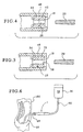
- Figure 1 illustrates a plan view of an embodiment of a connector of the present invention.
- Figure 2 illustrates a cross-sectional view taken generally along the line II-II of Figure 1 of a transfer set and a connector in a connected position.
- Figure 3 illustrates a cross-sectional view of an embodiment of a transfer set and a connector in an unconnected position.
- Figure 4 illustrates a cross-sectional view of an embodiment of a housing including two adjacent pieces therein.
- Figure 5 illustrates a cross-sectional view of an embodiment of a housing including a single piece having an area with disinfectant and an area with little or no disinfectant.
- Figure 6 illustrates an embodiment of a method of use of the connector of the present invention in a system for conducting peritoneal dialysis.
-
- The present invention provides a connection system including a disinfecting system for any system requiring a connection, such as connection of a first length of tubing or other conduit to a second length of tubing or other conduit, such as for peritoneal dialysis. The. present invention is designed to provide a safe and easy connection and disinfecting system for the user/patient without any mess.
- Although, in a preferred embodiment, the system of the present invention can be used for peritoneal dialysis, it should be appreciated that the system can be used for a variety of other applications.
- Pursuant to an embodiment of the present invention, the disinfectant system includes at least one ring. The ring may be a first piece without absorbent properties and a second piece with absorbent properties. The second piece has a disinfectant incorporated therein. At connection, a member to be disinfected passes through the first piece; then the member passes through the second piece where the member is disinfected. At disconnection, when the member is retracted, the member passes back through the first piece where the member is wiped dry.
- In a preferred embodiment, the second piece is a foam ring having open cell properties in which the disinfectant can be absorbed and held. The first piece is a material having closed cell properties, i.e. incapable of absorption, such that the first piece provides a wiping function. It should be understood, however, that the first piece and the second piece may be incorporated as a single piece having dual properties of absorption and non-absorption. Further, other materials other than foam may be implemented by those skilled in the art.
- Referring now to the drawings, Figure 1 generally illustrates an assembly 1 including a transfer set
connector 10 and adisposable connector 12 in a connected position. In an embodiment, a clamp 16 (shown in Figure 2) and afrangible member 14 are integral parts of thedisposable connector 12. Theclamp 16 is integrated into the body of thedisposable connector 12 to improve useability and, when activated, to prevent entrance of any contaminants from outside of thedisposable connector 12. - In an embodiment, the
clamp 16 is a C-type clamp having an arm that is depressible between a first position that compressestubing 15 connected in anarea 17 of theconnector 12 in which theclamp 16 is housed when theconnector 12 is connected to the transfer setconnector 10. Of course, it should be understood that other clamping methods may be implemented by those skilled in the art. The important feature of theclamp 16 is that theclamp 16 is functionally integrated in thearea 17 of theconnector 12. As a result, when abutton 24 of theconnector 12 is depressed, theclamp 16 may be forced to a position that depresses thetubing 15 so as to prevent flow in thetubing 15. - As further illustrated in Figures 1 and 2, the
connector 12, in an embodiment, is constructed from two portions. The connectingmember 36 attaches to the transfer setconnector 10 at one end and to thetubing 15 at its opposite end. Then, theconnector housing 35 attaches to the connectingmember 36 in a conventional manner so as to enclose thetubing 15 and theclamp 16 in thearea 17 defined between the connectingmember 36 and theconnector housing 35. - The
frangible member 14 and theclamp 16 allow the user/patient to clamp thetubing 15 then break away thefrangible member 14. Thefrangible member 14 is constructed and arranged such that breakage occurs slightly inside of theconnector housing 35. This feature helps limit the irritation that could occur to the user/patient, such as a peritoneal dialysis patient. Additionally, the proximity of theclamp 16 and thefrangible member 14 reduces the amount of residual volume that can accumulate. - In the preferred embodiment illustrated, the
button 24 is located on top of thedisposable connector 12. Thebutton 24, when depressed, occludes thetubing 15. Thefrangible member 14 is then broken by holding the connected assembly 1 and snapping off the end of thefrangible member 14. - Referring to Figure 2, the transfer set
connector 10 and thedisposable connector 12 are shown in the connected position. Anopening 28 is situated at a point intermediate ends of the transfer setconnector 10. Theopening 28 of the transfer setconnector 10 may be opened or closed in any manner known in the art, thereby increasing and decreasing the fluid flow through afluid path 46. - An
opening 28 is provided within ahousing 30 of the transfer setconnector 10 and anintegrated clamp 26. Thehousing 30 is rigid and in a fixed position relative to theintegrated clamp 26, which is both rigid and in an unfixed position. Theintegrated clamp 26 moves linearly from a point exterior to the outside of thehousing 30 to the inside of thehousing 30 through theend 50. Theopening 28 widens as theintegrated clamp 26 is retracted, increasing the flow rate of thefluid path 46. Aball 32 presses against aconical end 34 leading to theopening 28 to create a mechanical seal thus clamping off thefluid path 46. An O-ring 38 located inside thehousing 30 effectuates the seal. When theclamp 26 is retracted, theball 32 retracts allowing fluid flow. Fluid flow can be increased by further retraction of theball 32. Of course, other valving mechanisms, other than theball 32, may be implemented by those skilled in the art. Alternatively, the transfer setconnector 10 does not require a flow regulation mechanism. - Referring now to Figure 3, the transfer set
connector 10 and thedisposable connector 12 are shown in an unconnected state. The transfer setconnector 10 has a hollow, taperedmember 20 within thehousing 30. Thedisposable connector 12 has a similarly-sized hollow, taperedmember 22. Telescopic insertion of the hollow, taperedmember 20 into the hollow, taperedmember 22 creates fluid communication between thefluid path 46 and thetubing 15 of thedisposable connector 12. Sealing of thefluid path 46 occurs due to the differences in the hollow, taperedmember 20 and the hollow, taperedmember 22, one member being rigid and the other member being semi-rigid resulting in a mechanical seal. - The locking of the hollow, tapered
member 20 to the hollow, taperedmember 22 can be achieved independently of the sealing by use of an annular snap fit or any other method known in the art. The snap fit is designed to be activated after the seal has been established. - To further reduce the risk of "touch contamination", the transfer set
connector 10 and thedisposable connector 12 may be shrouded. If the transfer setconnector 10 and thedisposable connector 12 are shrouded, a groove (not shown) is located on the transfer setconnector 10 and a bead (not shown) is provided on thedisposable connector 12. If the transfer setconnector 10 and thedisposable connector 12 are not shrouded, then the groove is located on thedisposable connector 12 and the bead is located on the transfer setconnector 10. - In Figure 3, a dual
foam disinfectant system 18 is shown located in thedisposable connector 12 at or near anend 40 of thedisposable connector 12. At connection, the hollow taperedmember 20 of the transfer setconnector 10 passes through thedisinfectant system 18. The hollow taperedmember 20 can remain in nearly constant contact with the disinfectant during connection. - Referring now to Figure 4, the
disinfectant system 18 is shown having ahousing 48, anon-absorbent piece 42 and a secondabsorbent piece 44. - In a preferred embodiment of the present invention, the
first piece 42 has no disinfectant, and is, therefore, capable of wiping a liquid or gelatinous surface dry. Thesecond piece 44 has absorbent properties capable of incorporating a disinfectant for disinfecting a member that contacts thesecond piece 44. The type of materials used to form thepieces second piece 44, and closed cell materials are used for thefirst piece 42. Those skilled in the art may, of course, implement other materials having absorption and wiping properties. - In an embodiment of the present invention, the
first piece 42 is adjacent to thesecond piece 44 in thehousing 48. Thehousing 48 is constructed to prevent the twopieces housing 48. As previously mentioned, the twopieces - In another embodiment of the present invention, each of the
pieces first piece 42 has less disinfectant than thesecond piece 44 and is not absorbent. Thefirst piece 42 must be capable of wiping the member containing disinfectant dry. - At connection of the transfer set
connector 10 and thedisposable connector 12, themember 20 of the transfer setconnector 10 is inserted into anopening 28 and passes through thefirst piece 42 and then thesecond piece 44 of thedisposable connector 12, at which time themember 20 is coated with disinfectant. Upon disconnection of the transfer setconnector 10 and thedisposable connector 12, thefirst piece 42 wipes themember 20 of the transfer setconnector 10 dry. - In another embodiment, as illustrated in Figure 5, a
single piece 25 of material, may be implemented for thedisinfectant system 18, instead of two separate pieces. Pursuant to the present invention, when a single piece is used, afirst area 52 within thepiece 25 contains little or no disinfectant and asecond area 54 within thepiece 25 contains substantially more disinfectant. Thesingle piece 25 also includes an opening to receive a member for disinfection. - When the transfer set
connector 10 is connected to thedisposable connector 12 in the single piece system illustrated, themember 20 is inserted into anopening 28 and passes through thefirst area 52 and then thesecond area 54, at which time themember 20 is coated with disinfectant. At disconnection of the transfer setconnector 10 and thedisposable connector 12, themember 20 is retreated, and thefirst area 52 of thesingle piece 25 wipes themember 20 dry. - A method for using the connector assembly 1 during a peritoneal dialysis procedure is illustrated in Figure 6. A
first tubing 66 is in fluid communication with an interior of abag 56 including a supply ofdialysate 58. A second tubing or transfer settubing 68 is in fluid communication with a catheter which is implanted in aperitoneal cavity 60 of apatient 100. The connector assembly 1 of the present invention provides selective fluid communication between lengths oftubings bag 56 to theperitoneal cavity 60 of the patient. - Upon connection of the transfer set
tubing 68 to the transfer setconnector 10 of the connector assembly 1 and subsequent connection of the disposable connector with thefirst tubing 66, disinfection takes place with the absorbent and non-absorbent pieces within the connector assembly 1.
Claims (15)
- A connector (1) comprising:a housing (35, 36) defining an interior;a first piece (42) having wiping properties disposed within the housing interior;a second piece (44) having absorption properties disposed within the housing interior;a disinfectant within the second piece;an opening through the first and second pieces; characterized byan integrated clamp (26) that is adapted to close off the fluid path and to regulate the fluid flow.
- A connector according to claim 1, wherein the first piece (42) is adjacent to the second piece (44).
- A connector according to claim 1 or 2, wherein the first piece is dry.
- A connector according to any one of the preceding claims, wherein the first piece (42) and the second piece (44) are integrally formed.
- A connector according to any one of the preceding claims, wherein the housing is constructed and arranged to prevent the first piece and the second piece from moving within the connector.
- A connector according to any one of the preceding claims, wherein the second piece (44) is foam.
- A connector according to any one of the preceding claims, comprising a first member (10) and a second member (12) wherein the first and second members are substantially in constant contact with the disinfectant until disconnection.
- A connector according to any one of claims 1 to 6, wherein the housing (35, 36) is a first housing providing a first fluid pathway and wherein the connector further comprises a second housing (30) providing a second fluid pathway (46) and connection means for connecting the first and second fluid pathways to establish fluid communication therebetween.
- A connector according to claim 8, wherein the integrated clamp (26) is located within the second housing (30).
- A connector according to claim 8 or claim 9, further comprising a frangible member (14) operatively connected to the first housing (35, 36) wherein the frangible member (14) is detachable from the first housing (35, 36).
- A connector according to any one of the preceding claims, wherein the first piece and the second piece form a ring.
- Peritoneal dialysis apparatus comprising:a first member (12, 66) in fluid communication with a supply of dialysate (58);a second member (10, 68) adapted for fluid communication with a peritoneal cavity (60) of a patient (100);a connector as defined in any one of claims 1 to 6 which, when attached, provides selective fluid communication between the first member (12, 66) and the second member (10, 68);the second member (10, 68) being passable through the first and second pieces at connection; andretractable back through the first and second pieces at disconnection.
- The apparatus according to claim 12, wherein the second member (10, 68) passes through the first piece (42) prior to the second piece (44) at connection.
- The apparatus according to claim 12 or claim 13, wherein the second member is in substantially constant contact with the second piece during connection.
- The apparatus according to any one of claims 12 to 14, including means for sealing connection between the first member and the second member.
Applications Claiming Priority (3)
| Application Number | Priority Date | Filing Date | Title |
|---|---|---|---|
| US622969 | 1996-03-27 | ||
| US08/622,969 US5743892A (en) | 1996-03-27 | 1996-03-27 | Dual foam connection system for peritoneal dialysis and dual foam disinfectant system |
| PCT/US1997/003924 WO1997035634A1 (en) | 1996-03-27 | 1997-03-13 | Peritoneal dialysis tube connection with dual disinfectant system |
Publications (2)
| Publication Number | Publication Date |
|---|---|
| EP0851778A1 EP0851778A1 (en) | 1998-07-08 |
| EP0851778B1 true EP0851778B1 (en) | 2002-10-30 |
Family
ID=24496248
Family Applications (1)
| Application Number | Title | Priority Date | Filing Date |
|---|---|---|---|
| EP97915041A Expired - Lifetime EP0851778B1 (en) | 1996-03-27 | 1997-03-13 | Peritoneal dialysis tube connection with dual disinfectant system |
Country Status (13)
| Country | Link |
|---|---|
| US (1) | US5743892A (en) |
| EP (1) | EP0851778B1 (en) |
| JP (2) | JPH11506378A (en) |
| KR (1) | KR100453313B1 (en) |
| CN (1) | CN1146452C (en) |
| AT (1) | ATE226841T1 (en) |
| AU (1) | AU730399B2 (en) |
| BR (1) | BR9702136A (en) |
| CO (1) | CO4650193A1 (en) |
| DE (1) | DE69716707T2 (en) |
| ES (1) | ES2185923T3 (en) |
| TW (1) | TW325999B (en) |
| WO (1) | WO1997035634A1 (en) |
Cited By (1)
| Publication number | Priority date | Publication date | Assignee | Title |
|---|---|---|---|---|
| WO2024030300A1 (en) * | 2022-08-02 | 2024-02-08 | Baxter International Inc. | Aseptic peritoneal dialysis transfer set |
Families Citing this family (62)
| Publication number | Priority date | Publication date | Assignee | Title |
|---|---|---|---|---|
| DE19960226C1 (en) * | 1999-12-14 | 2001-05-10 | Fresenius Ag | Connection system, for two or more sterile systems, comprises male and female connectors with threshold breakage points inside the fluid supply system. |
| JP2003531687A (en) * | 2000-05-02 | 2003-10-28 | バスカ, インコーポレイテッド | Method and device for pumping fluid into or out of the body |
| ITBO20010497A1 (en) * | 2001-07-31 | 2003-01-31 | Delta Med S R L | PROTECTION DEVICE FOR NEEDLE-CANNULA |
| US6911025B2 (en) | 2002-01-25 | 2005-06-28 | Jms Co., Ltd. | Connector system for sterile connection |
| JP3972665B2 (en) | 2002-01-25 | 2007-09-05 | 株式会社ジェイ・エム・エス | Aseptic connector system |
| US7198611B2 (en) * | 2002-02-11 | 2007-04-03 | Baxter International Inc. | Dialysis connector and cap having an integral disinfectant |
| US7232419B2 (en) * | 2002-02-11 | 2007-06-19 | Baxter International Inc. | Enclosure with cam action snap release |
| ITMI20020819A1 (en) * | 2002-04-18 | 2003-10-20 | Gambro Lundia Ab | CONNECTION ELEMENT AND CONNECTION DEVICE FOR MEDICAL USE PIPES |
| US20130107938A9 (en) * | 2003-05-28 | 2013-05-02 | Chad Fogg | Method And Apparatus For Scalable Video Decoder Using An Enhancement Stream |
| SE0500494L (en) * | 2005-03-04 | 2005-12-13 | Novaseptic Ab | Method and apparatus for tightly interconnecting the ends of elongated elements such as hoses or lines |
| US7922701B2 (en) * | 2006-02-17 | 2011-04-12 | Buchman Alan L | Catheter cleaning devices |
| US20080033371A1 (en) * | 2006-06-26 | 2008-02-07 | Updegraff Debra K | Cover for catheter assembly |
| US8336152B2 (en) * | 2007-04-02 | 2012-12-25 | C. R. Bard, Inc. | Insert for a microbial scrubbing device |
| US8065773B2 (en) * | 2007-04-02 | 2011-11-29 | Bard Access Systems, Inc. | Microbial scrub brush |
| US9192449B2 (en) | 2007-04-02 | 2015-11-24 | C. R. Bard, Inc. | Medical component scrubbing device with detachable cap |
| US8157761B2 (en) * | 2007-07-05 | 2012-04-17 | Baxter International Inc. | Peritoneal dialysis patient connection system |
| US20090028750A1 (en) * | 2007-07-23 | 2009-01-29 | Ryan Dana Wm | Cleaning and Disinfection Swabbing Device for Needle-Free Intravenous (IV) Connectors |
| US8696820B2 (en) * | 2008-03-31 | 2014-04-15 | Bard Access Systems, Inc. | Method of removing a biofilm from a surface |
| US9348975B2 (en) * | 2008-05-02 | 2016-05-24 | Baxter International Inc. | Optimizing therapy outcomes for peritoneal dialysis |
| US8882700B2 (en) | 2008-05-02 | 2014-11-11 | Baxter International Inc. | Smart patient transfer set for peritoneal dialysis |
| WO2009136957A1 (en) | 2008-05-06 | 2009-11-12 | Ferlic Michael J | Universal sterilizing tool |
| US8252247B2 (en) | 2008-05-06 | 2012-08-28 | Ferlic Michael J | Universal sterilizing tool |
| US9572904B2 (en) | 2008-05-06 | 2017-02-21 | Michael J. Ferlic | Sterilizing device with pinch actuated cap and housing |
| US8069523B2 (en) * | 2008-10-02 | 2011-12-06 | Bard Access Systems, Inc. | Site scrub brush |
| US9078992B2 (en) | 2008-10-27 | 2015-07-14 | Pursuit Vascular, Inc. | Medical device for applying antimicrobial to proximal end of catheter |
| US20100130918A1 (en) * | 2008-11-21 | 2010-05-27 | Baxter International Inc. | Systems and methods for removing air from supply containers and associated fill tubing |
| US9555180B2 (en) * | 2008-11-21 | 2017-01-31 | Baxter International Inc. | Systems and methods for removing air from the patient's peritoneal cavity |
| US8080001B2 (en) * | 2008-11-26 | 2011-12-20 | Acist Medical Systems, Inc. | Fluid connection assembly with locking mechanism |
| EP2391404B1 (en) | 2009-01-30 | 2013-01-16 | Baxter International Inc. | Transfer sets for therapy optimization |
| KR20120004495A (en) * | 2009-04-01 | 2012-01-12 | 씨. 알. 바드, 인크. | Microbial cleaning device |
| US8753515B2 (en) | 2009-12-05 | 2014-06-17 | Home Dialysis Plus, Ltd. | Dialysis system with ultrafiltration control |
| US8501009B2 (en) | 2010-06-07 | 2013-08-06 | State Of Oregon Acting By And Through The State Board Of Higher Education On Behalf Of Oregon State University | Fluid purification system |
| KR101226216B1 (en) * | 2011-06-20 | 2013-01-30 | 심주현 | Peritoneal dialysis one touch connector with automatic shielding for preventing invasion of outside germs |
| ES2797649T3 (en) | 2011-07-12 | 2020-12-03 | Icu Medical Inc | Device for the delivery of antimicrobial agent in a transdermal catheter |
| CN103957960B (en) | 2011-10-07 | 2016-04-13 | 霍姆透析普拉斯有限公司 | Heat-exchange fluid for dialysis system purifies |
| US10195416B2 (en) | 2013-05-20 | 2019-02-05 | Ge Healthcare Bio-Sciences Ab | Apparatus and method for making a sterile connection of flexible tubing |
| US10792399B2 (en) | 2014-02-20 | 2020-10-06 | Becton, Dickinson And Company | Antimicrobial inserts for medical devices |
| US10792398B2 (en) | 2014-02-20 | 2020-10-06 | Becton, Dickinson And Company | Antimicrobial inserts for medical devices |
| US10149971B2 (en) | 2014-04-23 | 2018-12-11 | Becton, Dickinson And Company | Antimicrobial stopcock medical connector |
| EP3838308A1 (en) | 2014-04-29 | 2021-06-23 | Outset Medical, Inc. | Dialysis system and methods |
| AU2015252808B2 (en) | 2014-05-02 | 2019-02-21 | Excelsior Medical Corporation | Strip package for antiseptic cap |
| DE102014106458A1 (en) * | 2014-05-08 | 2015-11-12 | Sicos Gmbh | Connection device for a catheter, in particular a peripheral venous catheter (III) |
| US10569075B2 (en) | 2014-09-19 | 2020-02-25 | Children's Medical Center Corporation | Apparatuses for cleaning catheter ports |
| US10004890B2 (en) * | 2015-01-27 | 2018-06-26 | Becton, Dickinson And Company | Antimicrobial inserts for stopcock medical connectors |
| WO2016182822A1 (en) | 2015-05-08 | 2016-11-17 | Icu Medical, Inc. | Medical connectors configured to receive emitters of therapeutic agents |
| CN108883222B (en) | 2016-02-01 | 2023-01-17 | 利比迪公司 | Dialysis system pump with connectors |
| ES2908601T3 (en) | 2016-08-19 | 2022-05-03 | Outset Medical Inc | Peritoneal dialysis system and methods |
| EP4194043A1 (en) | 2016-10-14 | 2023-06-14 | ICU Medical, Inc. | Sanitizing caps for medical connectors |
| CN110234371A (en) | 2017-02-01 | 2019-09-13 | 利比迪公司 | Intelligent peritoneal dialysis device |
| WO2018204206A2 (en) | 2017-05-01 | 2018-11-08 | Icu Medical, Inc. | Medical fluid connectors and methods for providing additives in medical fluid lines |
| JP2021533881A (en) | 2018-08-23 | 2021-12-09 | アウトセット・メディカル・インコーポレイテッドOutset Medical, Inc. | Dialysis system and method |
| US11541220B2 (en) | 2018-11-07 | 2023-01-03 | Icu Medical, Inc. | Needleless connector with antimicrobial properties |
| US11534595B2 (en) | 2018-11-07 | 2022-12-27 | Icu Medical, Inc. | Device for delivering an antimicrobial composition into an infusion device |
| US11517732B2 (en) | 2018-11-07 | 2022-12-06 | Icu Medical, Inc. | Syringe with antimicrobial properties |
| US11400195B2 (en) | 2018-11-07 | 2022-08-02 | Icu Medical, Inc. | Peritoneal dialysis transfer set with antimicrobial properties |
| US11541221B2 (en) | 2018-11-07 | 2023-01-03 | Icu Medical, Inc. | Tubing set with antimicrobial properties |
| AU2019384564B2 (en) | 2018-11-21 | 2023-11-23 | Icu Medical, Inc. | Antimicrobial device comprising a cap with ring and insert |
| BR112021021836A2 (en) | 2019-04-30 | 2022-01-04 | Outset Medical Inc | Methods for calculating blood pressure, for creating dialysate in a dialysis system, for measuring the percentage of rejection in a dialysis system, for collecting and analyzing blood plasma, for removing gas from an extracorporeal circuit of a dialysis system, for inferring a line pressure in an extracorporeal circuit of a dialysis system, to provide extracorporeal and intracorporeal dialysis therapy, to mount a cartridge-style patient tube set in a dialysis machine, and to prepare a dialysis machine for dialysis therapy , air removal and flow chambers, dialysis system, dialysate dispensing subsystem, single-use microbe/endotoxin filter, dialyzer, device for measuring pressure from a dialysis system, and blood tube set |
| US11969572B2 (en) * | 2020-04-17 | 2024-04-30 | Becton, Dickinson And Company | Disinfection cap |
| JP2024500319A (en) | 2020-12-07 | 2024-01-09 | アイシーユー・メディカル・インコーポレーテッド | Peritoneal dialysis cap, system, and method |
| DE102022208343A1 (en) * | 2022-08-11 | 2024-02-22 | B. Braun Melsungen Aktiengesellschaft | Medical fluid connector system |
| US20250269165A1 (en) * | 2024-02-23 | 2025-08-28 | Baxter International Inc. | Transfer set with integrated disinfectant |
Family Cites Families (11)
| Publication number | Priority date | Publication date | Assignee | Title |
|---|---|---|---|---|
| US4354490A (en) * | 1980-06-09 | 1982-10-19 | Rogers Phillip P | Connector for ambulatory dialysis system |
| US4810241A (en) * | 1980-06-09 | 1989-03-07 | Rogers Phillip P | Ambulatory dialysis system and connector |
| US4655762A (en) * | 1980-06-09 | 1987-04-07 | Rogers Phillip P | Ambulatory dialysis system and connector |
| US4551146A (en) * | 1980-06-09 | 1985-11-05 | Phillip P. Rogers & Faye Rogers Living Trust | Connector for ambulatory dialysis system |
| FR2506162A1 (en) * | 1981-05-19 | 1982-11-26 | Smad Materiels Annexes Dialyse | Aseptic coupling for medical pipes esp. in peritoneal dialysis - has disinfectant pad in one half-coupling through which mating surface is advanced |
| HUT37357A (en) * | 1981-09-07 | 1985-12-28 | Ars Pro Medico Ag | Connecting member expediently for connecting one to another medical tubings |
| US4440207A (en) * | 1982-05-14 | 1984-04-03 | Baxter Travenol Laboratories, Inc. | Antibacterial protective cap for connectors |
| EP0183396A1 (en) * | 1984-11-08 | 1986-06-04 | Baxter Travenol Laboratories, Inc. | Connection site protector with tapered bore |
| JPS6279062A (en) * | 1985-09-30 | 1987-04-11 | 株式会社 日本メデイカル・サプライ | Method and apparatus for asceptic connection of connector |
| GB8615056D0 (en) * | 1986-06-20 | 1986-07-23 | Betabrook Ltd | Peritoneal dialysis |
| ES2027923A6 (en) * | 1991-01-30 | 1992-06-16 | Segura Badia Marcelo | Disinfecting connection for catheters and the like. |
-
1996
- 1996-03-27 US US08/622,969 patent/US5743892A/en not_active Expired - Lifetime
-
1997
- 1997-03-11 CO CO97013172A patent/CO4650193A1/en unknown
- 1997-03-13 CN CNB971902623A patent/CN1146452C/en not_active Expired - Fee Related
- 1997-03-13 AU AU22088/97A patent/AU730399B2/en not_active Ceased
- 1997-03-13 EP EP97915041A patent/EP0851778B1/en not_active Expired - Lifetime
- 1997-03-13 BR BR9702136A patent/BR9702136A/en not_active IP Right Cessation
- 1997-03-13 KR KR1019970708336A patent/KR100453313B1/en not_active Expired - Lifetime
- 1997-03-13 AT AT97915041T patent/ATE226841T1/en not_active IP Right Cessation
- 1997-03-13 ES ES97915041T patent/ES2185923T3/en not_active Expired - Lifetime
- 1997-03-13 DE DE69716707T patent/DE69716707T2/en not_active Expired - Lifetime
- 1997-03-13 WO PCT/US1997/003924 patent/WO1997035634A1/en not_active Ceased
- 1997-03-13 JP JP9534435A patent/JPH11506378A/en not_active Withdrawn
- 1997-03-15 TW TW086103231A patent/TW325999B/en not_active IP Right Cessation
-
2006
- 2006-10-23 JP JP2006287939A patent/JP2007050277A/en active Pending
Cited By (1)
| Publication number | Priority date | Publication date | Assignee | Title |
|---|---|---|---|---|
| WO2024030300A1 (en) * | 2022-08-02 | 2024-02-08 | Baxter International Inc. | Aseptic peritoneal dialysis transfer set |
Also Published As
| Publication number | Publication date |
|---|---|
| WO1997035634A1 (en) | 1997-10-02 |
| KR19990021862A (en) | 1999-03-25 |
| ES2185923T3 (en) | 2003-05-01 |
| ATE226841T1 (en) | 2002-11-15 |
| CN1185748A (en) | 1998-06-24 |
| CN1146452C (en) | 2004-04-21 |
| DE69716707D1 (en) | 2002-12-05 |
| BR9702136A (en) | 1999-01-05 |
| AU730399B2 (en) | 2001-03-08 |
| KR100453313B1 (en) | 2005-08-01 |
| JP2007050277A (en) | 2007-03-01 |
| US5743892A (en) | 1998-04-28 |
| EP0851778A1 (en) | 1998-07-08 |
| AU2208897A (en) | 1997-10-17 |
| DE69716707T2 (en) | 2003-06-12 |
| TW325999B (en) | 1998-02-01 |
| JPH11506378A (en) | 1999-06-08 |
| CO4650193A1 (en) | 1998-09-03 |
Similar Documents
| Publication | Publication Date | Title |
|---|---|---|
| US5743892A (en) | Dual foam connection system for peritoneal dialysis and dual foam disinfectant system | |
| US4432766A (en) | Conduit connectors having antiseptic application means | |
| US4738668A (en) | Conduit connectors having antiseptic application means | |
| US4983161A (en) | Method for using a connector cap and cover therefor | |
| US5221267A (en) | Breakable tubing coupling | |
| US5279605A (en) | Frangible spike connector for a solution bag | |
| US4338933A (en) | Combination quick disconnect coupling and liquid cutoff valve | |
| US4778447A (en) | Connectors | |
| KR910000412B1 (en) | Three-way connector for liquid exchange | |
| EP2473227B1 (en) | Cap for a male luer connector and having disinfecting means for female luer connector | |
| KR100356635B1 (en) | Medical Tubular Connectors | |
| US5190534A (en) | Prefilled sterilant fluid releasable coupling connector apparatus for catheter applications | |
| US4417890A (en) | Antibacterial closure | |
| US4457749A (en) | Shield for connectors | |
| US4366816A (en) | Combination quick disconnect coupling and fluid cutoff valve | |
| EP0680359B1 (en) | Connecting device | |
| US4624664A (en) | Antibacterial closure system | |
| US20010020787A1 (en) | Connector having an inner displacement member | |
| US4551130A (en) | Surgical drainage and irrigation apparatus for post operative patient care | |
| CA2119657A1 (en) | Terminal self-releasing fluid reservoir | |
| JPH0372A (en) | Exchange method for container for medical treatment | |
| US5827238A (en) | Roller clamp-connector assembly | |
| JPH0531180A (en) | Medical connection | |
| EP0084552B1 (en) | Conduit connectors having antiseptic application means | |
| CN222549203U (en) | Systems for line extraction, flushing and blood collection |
Legal Events
| Date | Code | Title | Description |
|---|---|---|---|
| PUAI | Public reference made under article 153(3) epc to a published international application that has entered the european phase |
Free format text: ORIGINAL CODE: 0009012 |
|
| 17P | Request for examination filed |
Effective date: 19970818 |
|
| AK | Designated contracting states |
Kind code of ref document: A1 Designated state(s): AT BE CH DE DK ES FR GB GR IT LI NL SE |
|
| 17Q | First examination report despatched |
Effective date: 20000629 |
|
| GRAG | Despatch of communication of intention to grant |
Free format text: ORIGINAL CODE: EPIDOS AGRA |
|
| GRAG | Despatch of communication of intention to grant |
Free format text: ORIGINAL CODE: EPIDOS AGRA |
|
| GRAH | Despatch of communication of intention to grant a patent |
Free format text: ORIGINAL CODE: EPIDOS IGRA |
|
| GRAH | Despatch of communication of intention to grant a patent |
Free format text: ORIGINAL CODE: EPIDOS IGRA |
|
| GRAA | (expected) grant |
Free format text: ORIGINAL CODE: 0009210 |
|
| AK | Designated contracting states |
Kind code of ref document: B1 Designated state(s): AT BE CH DE DK ES FR GB GR IT LI NL SE |
|
| PG25 | Lapsed in a contracting state [announced via postgrant information from national office to epo] |
Ref country code: NL Free format text: LAPSE BECAUSE OF FAILURE TO SUBMIT A TRANSLATION OF THE DESCRIPTION OR TO PAY THE FEE WITHIN THE PRESCRIBED TIME-LIMIT Effective date: 20021030 Ref country code: LI Free format text: LAPSE BECAUSE OF FAILURE TO SUBMIT A TRANSLATION OF THE DESCRIPTION OR TO PAY THE FEE WITHIN THE PRESCRIBED TIME-LIMIT Effective date: 20021030 Ref country code: IT Free format text: LAPSE BECAUSE OF FAILURE TO SUBMIT A TRANSLATION OF THE DESCRIPTION OR TO PAY THE FEE WITHIN THE PRESCRIBED TIME-LIMIT;WARNING: LAPSES OF ITALIAN PATENTS WITH EFFECTIVE DATE BEFORE 2007 MAY HAVE OCCURRED AT ANY TIME BEFORE 2007. THE CORRECT EFFECTIVE DATE MAY BE DIFFERENT FROM THE ONE RECORDED. Effective date: 20021030 Ref country code: GR Free format text: LAPSE BECAUSE OF FAILURE TO SUBMIT A TRANSLATION OF THE DESCRIPTION OR TO PAY THE FEE WITHIN THE PRESCRIBED TIME-LIMIT Effective date: 20021030 Ref country code: CH Free format text: LAPSE BECAUSE OF FAILURE TO SUBMIT A TRANSLATION OF THE DESCRIPTION OR TO PAY THE FEE WITHIN THE PRESCRIBED TIME-LIMIT Effective date: 20021030 Ref country code: BE Free format text: LAPSE BECAUSE OF FAILURE TO SUBMIT A TRANSLATION OF THE DESCRIPTION OR TO PAY THE FEE WITHIN THE PRESCRIBED TIME-LIMIT Effective date: 20021030 Ref country code: AT Free format text: LAPSE BECAUSE OF FAILURE TO SUBMIT A TRANSLATION OF THE DESCRIPTION OR TO PAY THE FEE WITHIN THE PRESCRIBED TIME-LIMIT Effective date: 20021030 |
|
| REF | Corresponds to: |
Ref document number: 226841 Country of ref document: AT Date of ref document: 20021115 Kind code of ref document: T |
|
| REG | Reference to a national code |
Ref country code: GB Ref legal event code: FG4D |
|
| REG | Reference to a national code |
Ref country code: CH Ref legal event code: EP |
|
| REF | Corresponds to: |
Ref document number: 69716707 Country of ref document: DE Date of ref document: 20021205 |
|
| PG25 | Lapsed in a contracting state [announced via postgrant information from national office to epo] |
Ref country code: DK Free format text: LAPSE BECAUSE OF FAILURE TO SUBMIT A TRANSLATION OF THE DESCRIPTION OR TO PAY THE FEE WITHIN THE PRESCRIBED TIME-LIMIT Effective date: 20030130 |
|
| ET | Fr: translation filed | ||
| NLV1 | Nl: lapsed or annulled due to failure to fulfill the requirements of art. 29p and 29m of the patents act | ||
| REG | Reference to a national code |
Ref country code: ES Ref legal event code: FG2A Ref document number: 2185923 Country of ref document: ES Kind code of ref document: T3 |
|
| REG | Reference to a national code |
Ref country code: CH Ref legal event code: PL |
|
| PLBE | No opposition filed within time limit |
Free format text: ORIGINAL CODE: 0009261 |
|
| STAA | Information on the status of an ep patent application or granted ep patent |
Free format text: STATUS: NO OPPOSITION FILED WITHIN TIME LIMIT |
|
| 26N | No opposition filed |
Effective date: 20030731 |
|
| PGFP | Annual fee paid to national office [announced via postgrant information from national office to epo] |
Ref country code: ES Payment date: 20040407 Year of fee payment: 8 |
|
| PG25 | Lapsed in a contracting state [announced via postgrant information from national office to epo] |
Ref country code: ES Free format text: LAPSE BECAUSE OF NON-PAYMENT OF DUE FEES Effective date: 20050314 |
|
| REG | Reference to a national code |
Ref country code: ES Ref legal event code: FD2A Effective date: 20050314 |
|
| PGFP | Annual fee paid to national office [announced via postgrant information from national office to epo] |
Ref country code: SE Payment date: 20110329 Year of fee payment: 15 |
|
| REG | Reference to a national code |
Ref country code: SE Ref legal event code: EUG |
|
| PG25 | Lapsed in a contracting state [announced via postgrant information from national office to epo] |
Ref country code: SE Free format text: LAPSE BECAUSE OF NON-PAYMENT OF DUE FEES Effective date: 20120314 |
|
| REG | Reference to a national code |
Ref country code: FR Ref legal event code: PLFP Year of fee payment: 19 |
|
| PGFP | Annual fee paid to national office [announced via postgrant information from national office to epo] |
Ref country code: DE Payment date: 20150327 Year of fee payment: 19 |
|
| PGFP | Annual fee paid to national office [announced via postgrant information from national office to epo] |
Ref country code: FR Payment date: 20150317 Year of fee payment: 19 Ref country code: GB Payment date: 20150327 Year of fee payment: 19 |
|
| REG | Reference to a national code |
Ref country code: DE Ref legal event code: R119 Ref document number: 69716707 Country of ref document: DE |
|
| GBPC | Gb: european patent ceased through non-payment of renewal fee |
Effective date: 20160313 |
|
| REG | Reference to a national code |
Ref country code: FR Ref legal event code: ST Effective date: 20161130 |
|
| PG25 | Lapsed in a contracting state [announced via postgrant information from national office to epo] |
Ref country code: FR Free format text: LAPSE BECAUSE OF NON-PAYMENT OF DUE FEES Effective date: 20160331 Ref country code: GB Free format text: LAPSE BECAUSE OF NON-PAYMENT OF DUE FEES Effective date: 20160313 Ref country code: DE Free format text: LAPSE BECAUSE OF NON-PAYMENT OF DUE FEES Effective date: 20161001 |