BACKGROUND OF THE INVENTION
Field of the Invention
The invention relates to a powdery material for an
active material which is the main material of a
secondary cell using an alkali as the electrolyte,
electrode members such as negative electrode and
positive electrode and a secondary cell. More
particularly, the invention relates to a powdery
material of a hydrogen-storing compound (hydrogen
storage compound) for use as the main material of a
negative electrode, a negative electrode formed of the
hydrogen-storing compound powdery material, a powdery
material comprised of nickel hydroxide subjected to
coating treatment for use as the main material of a
positive electrode, a positive electrode formed of the
nickel hydroxide, a secondary cell comprising the above
negative electrode and/or the above positive electrode
and a method for manufacturing these.
Related Background Art
Recently, since the amount of CO2 gas contained in
the atmosphere increases, the possibility of global
warming to occur due to the greenhouse effect has been
pointed out. For example, in a thermal power plant,
thermal energy obtained by burning of fossil fuel and
the like is converted into electric energy, but the
construction of a new thermal power plant has become
difficult because a great amount of CO2 gas is
discharged by burning. Thus, as an effective
utilization of electric power produced by generators of
a thermal power plant or the like, a so-called load
levelling, levelling of loads by storing the night
power as surplus power into secondary cells installed
at general houses and using it at the daytime during
which the power consumption is large, is proposed.
For an electric automobile which discharges no
substance containing COx, NOx, hydrocarbons or the like
associated with air pollution, the development of
secondary cells having an indispensable high energy
density is expected. Furthermore, in uses for power
sources of portable equipments such as book-type
personal computers, word processors, video cameras and
portable telephones, the development of a small-sized,
light-weight and high-performance secondary cell is an
urgent need.
Under such circumstances as mentioned above, a
high-capacity secondary cell using a hydrogen-storing
alloy storing hydrogen at a high density for the
negative electrode of an alkali secondary cell with an
alkali solution employed as the electrolyte, what is
called nickel-metal hydride battery (cell)
(hereinafter, referred to as nickel-metal hydride
battery) has been put into practical use.
As hydrogen-storing alloys for the negative
electrode of a hydrogen-storing alloy, Mischmetal
alloys typified by Mm(Ni-Co-Mn-Al)5, transition metal
alloys typified by Ti-Zr-Ni-V-Cr-Co-Mn and magnesium-nickel
alloys such as Mg2Ni and MgNi have been
researched and the Mischmetal alloys and the transition
metal alloys are put into practical use as electrode
materials.
Both the Mischmetal alloys and the transition
metal alloys have a practical capacity lower than the
theoretical capacity and are desired to be further
improved. Besides, as compared with the nickel-cadmium
battery using a cadmium negative electrode, they have
had a problem of being subject to oxidization and
deterioration during the overcharge. In this regard, a
method of coating hydrogen-storing alloy powder with an
oxidation-resistant metal is proposed in Japanese
Patent Application Laid-Open Nos. 61-64069 and 61-101957,
but no secondary cell sufficiently more
resistant to overcharge than the nickel-cadmium battery
has yet been obtained.
With respect to the magnesium-nickel alloys, it
was made public in the 37-th Battery Symposium in
Japan, p. 389 (1996) that as high discharge capacity as
750 mAh/g at the first time of the charge-discharge
cycle was obtained in an electrode using a Mg2Ni alloy
powder prepared by the mechanical grinding method, but
the discharge capacity decreased with the progress of
the charge-discharge cycle and no magnesium-nickel
alloy electrode having a stable high discharge capacity
has yet been obtained.
In the nickel-metal hydride battery, nickel
hydroxide is employed as a positive electrode active
material as is the case of the positive electrodes of
other alkali secondary cells such as the nickel-cadmium
battery. Since this nickel hydroxide is low in
conductivity, cobalt monoxide or cobalt hydroxide are
added in forming the positive electrode in addition to
nickel hydroxide to increase the conductivity, thereby
enhancing the utilizing efficiency of the positive
electrode active material. However, there has been
remained a problem that the utilizing efficiency of the
positive electrode active material of the battery at
the initial stage of the charge-discharge cycle is low.
SUMMARY OF THE INVENTION
It is, therefore, an object of the present
invention to provide in secondary cells using an alkali
as the electrolyte, especially in the so-called nickel-metal
hydride battery, a material comprising a compound
which is non-oxidizable and large in the hydrogen
storing amount, an electrode member suitable as a
negative electrode having a large amount of hydrogen
storage in an electrochemical reaction, an electrode
member suitable as a positive electrode having a high
efficiency of utilization and a large-electric-capacity
(nickel-metal hydride) secondary cell using these.
Besides, it is another object of the present invention
to provide a method for manufacturing an electrode
member of the material mentioned above.
The most specific feature of the present invention
lies in a powdery material comprising a hydrogen-storing
compound comprising a core layer mainly coposed
of a hydrogen storage alloy, a metal oxide layer
(second layer) provided on the core layer for imparting
oxidation resistance and a dispersed metal element
layer (third layer) provided on the oxidation resistant
layer for activating hydrogen, with the three separate
functions provided for the respective layers, in an
electrode member formed of the above powdery material
as the main material and in a secondary cell using the
above electrode member as the negative electrode and an
alkali as the electrolyte. Next, another specific
feature of the present invention lies in a powdery
material comprising nickel hydroxide coated with a
compound comprising a transition metal and oxygen
element and being higher in conductivity than nickel
hydroxide, in an electrode member formed of the nickel
hydroxide powder coated with the above compound and in
a secondary cell using the above electrode member as
the positive electrode and an alkali as the
electrolyte.
Besides, according to the present invention, a
powdery material comprising a core part having a
function of storing hydrogen comprising a magnesium-nickel
alloy as the main component and a metal oxide
layer imparting resistance to oxidation provided on the
surface of the core part, an electrode member composed
of the powdery material as the main material and a
secondary cell using the electrode member as the
negative electrode and an alkali for the electrolyte
are provided.
BRIEF DESCRIPTION OF THE DRAWINGS
FIG. 1 is a sectional view schematically showing
an example of structure of a powdery material according
to the present invention;
FIG. 2 is a sectional view schematically showing
an example of an electrode member (negative electrode)
according to the present invention;
FIG. 3 is a sectional view schematically showing
another example of structure of a powdery material
according to the present invention;
FIG. 4 is a sectional view schematically showing
an example of an electrode member (positive electrode)
according to the present invention;
FIG. 5 is a schematically sectional view of an
example of an alkali secondary cell according to the
present invention;
FIG. 6 is a sectional view of an example of a
coin-shaped cell;
FIG. 7 is a sectional view of an example of a
spiral type cylindrical cell;
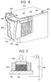
FIG. 8 is a sectional view of an example of a
rectangular tpye shaped cell; and
FIG. 9 is a schematically sectional view of an
example of a powder resistance measuring device used to
measure the difference in conductivity between the
presence and the absence of coating treatment of nickel
hydroxide powder forming the positive electrode active
material according to the present invention.
DETAILED DESCRIPTION OF THE PREFERRED EMBODIMENTS
A first aspect of the present invention is a
powdery material comprising a compound having a
function of storing and releasing hydrogen, having a
structure of at least three layers of a core comprising
a hydrogen-storing alloy, a metal oxide layer provided
on the surface of the core and having a function of
preventing the oxidation of the alloy and allowing
atomic hydrogen or hydrogen ions to pass therethrough
and a layer having dispersed a metal element having a
function of activating hydrogen provided on the surface
of the metal oxide layer. In the present invention,
the metal oxide layer having a function of preventing
the oxidation and allowing atomic hydrogen or hydrogen
ions to pass therethrough is preferably comprised of a
transition metal oxide layer comprising at least one
transition metal selected from molybdenum, tungsten,
vanadium, niobium, titanium, zirconium and iridium and
oxygen element. Besides, the dispersed metal element
for activating hydrogen is preferably at least one
transition metal element selected from nickel,
chromium, molybdenum, cobalt, copper, palladium,
platinum, iron, ruthenium, rhodium, iridium, tungsten,
titanium and manganese.
A second aspect of the present invention is an
electrode member for batteries which is formed of a
powdery material as the main material comprising a
compound having a function of storing and releasing
hydrogen, having a structure of at least three layers
of a core comprising a hydrogen-storing alloy, a metal
oxide layer provided on the surface of the core and
having a function of preventing the oxidation of the
alloy and allowing atomic hydrogen or hydrogen ions to
pass therethrough and a layer having dispersed a metal
element having a function of activating hydrogen
provided on the surface of the metal oxide layer, and
which stores and releases hydrogen electrochemically.
Such an electrode member is suitably used for the
negative electrode of a secondary cell
electrochemically utilizing the storage reaction of
hydrogen.
Furthermore, a third aspect of the present
invention is a secondary cell comprising at least a
negative electrode (i.e., anode), an electrolyte and a
positive electrode (i.e., cathode) wherein the negative
electrode is formed of a powdery material as the main
material comprising a compound having a function of
storing and releasing hydrogen, having a structure of
at least three layers of a core comprising a hydrogen-storing
alloy, a metal oxide layer provided on the
surface of the core and having a function of preventing
the oxidation of the alloy and allowing atomic hydrogen
or hydrogen ions to pass therethrough and a layer
having dispersed a metal element having a function of
activating hydrogen provided on the surface of the
metal oxide layer.
A fourth aspect of the present invention is a
powdery material comprising nickel hydroxide (Ni(OH)2)
coated either with a compound higher in conductivity
than nickel hydroxide comprising at least one element
selected from cobalt element and nickel element and
oxygen element and containing 0.5 atomic % to 10
atomic % of at least one element selected from lithium,
potassium, manganese, aluminum, zinc, magnesium,
molybdenum, tungsten, vanadium and titanium or with a
compound higher in conductivity than nickel hydroxide
comprising at least one transition metal element
selected from molybdenum, tungsten, vanadium and
titanium and oxygen and hydrogen elements.
A fifth aspect of the present invention is an
electrode member composed of a powdery material as the
main material comprising nickel hydroxide (Ni(OH)2)
coated either with a compound higher in conductivity
than nickel hydroxide comprising at least one element
selected from cobalt element and nickel element and
oxygen element and containing 0.5 atomic % to 10
atomic % of at least one element selected from lithium,
potassium, manganese, aluminum, zinc, magnesium,
molybdenum, tungsten, vanadium and titanium, or with a
compound higher in conductivity than nickel hydroxide
comprising at least one transition metal element
selected from molybdenum, tungsten, vanadium and
titanium and oxygen and hydrogen elements. Such an
electrode member is suitably employed as a positive
electrode of a second cell using an alkali as the
electrolyte.
A sixth aspect of the present invention is a
secondary cell comprising at least a negative
electrode, a positive electrode and an alkali
electrolyte wherein the positive electrode is composed
of a powdery material as the main material comprising
nickel hydroxide (Ni(OH)2) coated either with a compound
higher in conductivity than nickel hydroxide,
comprising at least one element selected from cobalt
element and nickel element and oxygen element and
containing 10 atomic % or less of at least one element
selected from lithium, potassium, manganese, aluminum,
zinc, magnesium, molybdenum, tungsten, vanadium and
titanium, or with a compound higher in conductivity
than nickel hydroxide and insoluble in an alkali,
comprising at least one transition metal element
selected from molybdenum, tungsten, vanadium and
titanium and oxygen and hydrogen elements.
Incidentally, in the present invention (the
present specification), "nickel hydroxide" signifies
nickel (II) hydroxide (Ni(OH)2).
Furthermore, as a seventh aspect of the present
invention, there is provided a secondary cell
comprising at least a negative electrode, a positive
electrode and an alkali electrolyte wherein the
negative electrode is formed of a powdery material as
the main material comprising a compound having a
function of storing and releasing hydrogen, having a
structure of at least three layers of a core comprising
a hydrogen-storing alloy, a metal oxide layer provided
on the surface of the core and having a function of
preventing the oxidation of the alloy and allowing
atomic hydrogen or hydrogen ions to pass therethrough
and a layer having dispersed a metal element having a
function of activating hydrogen provided on the surface
of the metal oxide layer and wherein the positive
electrode is formed of a powdery material as the main
material comprising a nickel hydroxide (Ni(OH)2) coated
either with a compound higher in conductivity than
nickel hydroxide, comprising at least one element
selected from cobalt element and nickel element and
oxygen element and containing 0.5 atomic % to 10 atomic
% or less of at least one element selected from
lithium, potassium, manganese, aluminum, zinc,
magnesium, molybdenum, tungsten, vanadium and titanium,
or with a compound higher in conductivity than nickel
hydroxide and insoluble in an alkali, comprising at
least one transition metal element selected from
molybdenum, tungsten, vanadium and titanium and oxygen
and hydrogen elements.
An eighth aspect of the present invention is a
method for manufacturing a powdery material forming the
main constituent of the electrode (negative electrode)
of a secondary cell, preferably using an alkali as the
electrolyte and especially preferably utilizing the
electrochemical storage reaction of hydrogen,
comprising at least the steps of preparing a core
comprising a hydrogen-storing alloy, providing on the
surface of the core a metal oxide layer having a
function of preventing the oxidation of the alloy and
allowing atomic hydrogen or hydrogen ions to pass
therethrough and dispersing on the surface of the metal
oxide layer a metal element having a function of
activating hydrogen, or comprising at least the step of
providing, on the surface of a core comprising an alloy
of magnesium and nickel as the main component having
the hydrogen storing function, a metal oxide layer
having a function of preventing the oxidation of the
alloy and allowing atomic hydrogen or hydrogen ions to
pass therethrough.
A ninth aspect of the present invention is a
method for manufacturing an electrode member (negative
electrode) employed in a secondary cell, preferably
using an alkali as the electrolyte and especially
preferably utilizing the electrochemical storage
reaction of hydrogen, comprising, in addition to the
above-mentioned manufacturing steps of a powdery
material comprising a hydrogen-storing compound, the
step of forming an electrode member from the above
compound powder and a collector. Besides, in the above
method for manufacturing a negative electrode,
preferably at least two auxiliary conductive materials
different in shape may be added to the above compound
powder and the mixture may be shaped on the electric
collector.
A tenth aspect of the present invention is a
method for manufacturing a powdery material as the main
material of an electrode (positive electrode) employed
in a secondary cell preferably using an alkali as the
electrolyte, comprising the step of coating nickel
hydroxide powder either with a compound higher in
conductivity than nickel hydroxide comprising at least
one element selected from cobalt element and nickel
element and oxygen element and containing 0.5 atomic %
to 10 atomic % of at least one element selected from
lithium, potassium, manganese, aluminum, zinc,
magnesium, molybdenum, tungsten, vanadium and titanium,
or with a compound higher in conductivity than nickel
hydroxide comprising at least one element selected from
molybdenum, tungsten, vanadium and titanium and oxygen
elements.
An eleventh aspect of the present invention is a
method for manufacturing an electrode member serving
the positive electrode in a secondary cell preferably
using an alkali as the electrolyte, comprising, in
addition to the above-mentioned coating treatment step
of nickel hydroxide powdery, the step of forming an
electrode member from the powdery material comprising
nickel hydroxide subjected to the coating treatment and
a collector.
A powdery material according to the first aspect
of the present invention is applicable to the negative
electrode active material powder of a secondary cell
preferably using an alkali as the electrolyte, can
impart separate functions to respective layers by
employing a hydrogen-storing alloy powder as a core
layer, coating the surface thereof with a metal oxide
layer comprising a metal element and oxygen element and
dispersing and having carried the metal on the
outermost surface; that is, can adsorb hydrogen on the
dispersed metal layer of the top surface, generate an
active atomic hydrogen or hydrogen ions by the
catalysis of the transition metal efficiently and
storing the atomic hydrogen or hydrogen ions passing
through the metal oxide layer for preventing the
oxidation of the hydrogen-storing alloy into the
hydrogen-storing alloy of the core layer.
Besides, in the powdery material using a
magnesium-nickel alloy as the core layer, the
magnesium-nickel alloy, is preferably made amorphous by
a technique such as mechanical alloying and mechanical
grinding so that an excellent electrochemical hydrogen
storage function is obtained even at room temperature.
However, when charging and discharging cycle is
repeated in the case of using such a powdery material
as the negative electrode material of a nickel-metal
hydride cell, there may be occured a problem that the
reaction of an alkaline electrolyte solution with the
alloy causes an abrupt lowering in hydrogen storage
function (charged electric quantity) of the negative
electrode. Thus, in the case of using the powdery
material as the negative electrode material of a
nickel-metal hydride cell, coating at least the core
layer comprised of a magnesium-nickel alloy with a
metal oxide inhibits the deterioration of the core
layer due to the reaction of an alkaline electrolyte
solution with the core layer comprised of the alloy and
prevents the above-mentioned abrupt lowering in
hydrogen storage function, thus implementing a high-capacity
alkali secondary cell.
Furthermore, by composing the above metal oxide
layer of a transition metal oxide layer comprising at
least one transition metal element selected from
molybdenum, tungsten, vanadium, niobium, titanium,
zirconium and iridium and oxygen element, a layer to
allow the atomic hydrogen or hydrogen ions generated on
the top surface layer to easily pass therethrough to
the core layer of the hydrogen-storing alloy can be
formed. Further, forming a compound oxide of the
above-mentioned metal oxide with at least one oxide
selected from aluminum oxides and silicon oxides can
improve alkali resistance. Besides, by employing at
least one transition metal selected from nickel,
chromium, molybdenum, cobalt, copper, palladium,
platinum, iron, ruthenium, rhodium, iridium, tungsten,
titanium and manganese as the metal to be dispersed on
the outermost surface, it becomes possible to easily
adsorb hydrogen and to easily generate atomic hydrogen
or hydrogen ions.
By employing the powdery material comprising a
compound having a function of storing hydrogen
(compound powder) as the main material of a negative
electrode active material to form an electrode
(negative electrode) and by adopting this for the
negative electrode of an alkali secondary cell, the
amount of hydrogen stored by the charge reaction
increases and the charging efficiency, the charging
capacity and the discharging capacity also increase.
Besides, it becomes possible to obtain an alkali
secondary cell according to the third aspect of the
present invention comprising a negative electrode less
subject to functional deterioration due to oxygen gas
generated at the overcharge. Furthermore, since by
adding at least two powdery auxiliary conductive
materials of different shapes selected from shapes of
flake, sphere, filament, needle, spike and such others
to the powdery material mentioned above (negative
electrode active material) to form an electrode member,
the impedance can be reduced, adoping this electrode as
the negative electrode in an alkali secondary cell can
be provided a secondary cell of a high charging and
discharging efficiency and a long cycle life. Since
adding auxiliary conductive materials of at least two
different shapes selected from shapes of flake, sphere,
filament, needle, spike and such others can increase
the packing density of the negative electrode active
material and the auxiliary conductive materials, the
impedance of the negative electrode can be reduced.
Furthermore, the fourth aspect of the present
invention is a powdery material comprising nickel
hydroxide coated with a layer of a compound higher in
conductivity than nickel hydroxide comprising at least
a transition metal element and oxygen element,
preferably usable for the positive electrode active
material of an alkali secondary cell. Besides, in an
electrode member formed of the nickel hydroxide powder
(powdery material) coated with the above compound layer
comprising at least a transition metal element and
oxygen element and a collector (electrode member
according to the fifth aspect of the present
invention), the nickel hydroxide powder of the active
material (positive electrode active material) is coated
with the coating layer higher in conductivity than
nickel hydroxide, and accordingly use of this member as
the positive electrode of a secondary cell enhances the
electronic conductivity in the nickel hydroxide powder
as compared with a positive electrode formed of nickel
hydroxide without a coating layer, thereby enabling the
impedance to be reduced. Besides, adopting the
positive electrode for an alkali secondary cell enables
an alkali secondary cell (secondary cell according to
the sixth aspect of the present invention) having a
high utilizing efficiency of the positive electrode
active material in the charging and discharging
reactions and a large charging capacity and discharging
capacity to be obtained.
Furthermore, it is preferred that at least 1 %
by weight to 30% by weight of nickel (II) nickel (III)
hydroxide (Ni3O2(OH)4) be contained in addition to the
nickel hydroxide powder mentioned above to make an
electrode member (positive electrode). In this case,
since the positive electrode of an unused secondary
cell is composed of at least 1% by weight to 30% by
weight of nickel (II) nickel (III) hydroxide in
addition to the nickel hydroxide mentioned above of the
main material and since the density of nickel (II)
nickel (III) hydroxide (Ni3O2(OH)4) is smaller than that
of nickel hydroxide Ni(OH)2, even when low-density γ-type
nickel oxyhydroxide (γ-NiOOH) is formed at
overcharge or at charge of a high efficiency, the
expansion of the electrode can be prevented to suppress
deterioration of life. Further, Ni3O2(OH)4 has a high
oxidation value of nickel and therefore contributes to
increase of capacity at discharge.
In addition, the adoption of an electrode member
using the powdery material according to the first
aspect of the present invention as the negative
electrode and of an electrode member of the powdery
material according to the fourth aspect of the present
invention as the positive electrode enables an alkali
secondary cell, especially preferably a nickel-metal
hydride secondary cell, high in capacity, high in
charging and discharging efficiency, resistant to
overcharge and long in cycle life to be obtained.
Furthermore, in the present invention, the above-mentioned
powdery material (compound powder) comprising
the hydrogen-storing compound is prepared by forming a
layer comprising a transition metal oxide on the
surface of hydrogen-storing alloy powder. Then, a
transition metal is dispersed and carried on the
outermost surface. The above-mentioned transition
metal oxide layer can be easily formed by dipping
hydrogen-storing alloy powder into one or more
solutions selected from a polymetallic acid salt
solution, a peroxopolymetallic acid solution and a
metallic acid solution of at least one metal element
selected from molybdenum, tungsten, vanadium, niobium,
titanium, zirconium, and iridium. At that time, by
adding an alumina sol or silica sol solution, formation
of a compound oxide with an aluminum oxide or silicon
oxide can be attained to improve alkali resistance.
Furthermore, by adding the hydroxide or salt of an
alkali metal element, an alkali earth metal element and
a rare earth metal element to the one or more solutions
of the polymetallic acid salt solution,
peroxopolymetallic acid solution and metallic acid
solution mentioned above, a transition metal oxide
layer containing at least one metal element selected
from an alkali metal element, an alkaline earth metal
element and a rare earth metal element can be easily
formed. The addition of the above-mentioned alkali
metal element, alkaline earth metal element or rare
earth metal element enables the conductivity of the
transition metal oxide to be improved. Furthermore,
the dispersing and carrying of the transition metal
mentioned above onto the outermost surface can be
easily accomplished by depositing the salt of at least
one transition metal element selected from nickel,
chromium, molybdenum, cobalt, copper, palladium,
platinum, iron, ruthenium, rhodium, iridium, tungsten,
titanium and manganese thereon and then, directly
reducing the salt of the transition metal element or by
allowing a precipitant such as an alkali to react with
the salt of the transition metal element to deposit a
transition metal hydroxide or the like once and
subjecting it reducing treatment. The above bypass
through a hydroxide of the transition metal enables the
reduction temperature for reduction to metal to be
lowered.
Besides, in the present invention, magnesium-nickel
alloy powder, as one example of hydrogen-storing
alloy powder used for the core layer of the powder
material comprising the hydrogen-storing compound can
be simply prepared by dipping magnesium powder in a
nickel salt solution and employing a chemical reaction
utilizing a difference in ionization tendency.
Furthermore, by similarly employing a chemical reaction
utilizing a difference in ionization tendency, a trace
element can be easily introduced into the alloy by
replacing a part of magnesium element in the magnesium-nickel
alloy powder with at least one element selected
from elements smaller in ionization tendency such as
titanium, beryllium, manganese, aluminum, zinc,
chromium, iron, indium, cobalt, molybdenum, tin, lead,
antimony, bismuth, copper, silver, palladium and
platinum. The introduction of the trace element in an
amount of 20 atomic % or less makes it possible to
obtain a compound powder which electrochemically stores
and releases hydrogen more stably.
Furthermore, in the present invention, at least
two powdery auxiliary conductive materials of different
shapes selected from shapes of flake, sphere and
filament, or the like comprised of at least one
material selected from a carbonaceous material
(preferably, amorphous carbon or graphite), nickel,
copper, silver, indium and tin are mixed with the
compound powder prepared above for a core of a
hydrogen-storing alloy and a binding agent of an
organic polymer or the like or a solvent is further
added if necessary and by subjecting this mixture to
the technique of application, press or sintering, an
electrode member having an active material layer
(negative electrode active material layer) of a reduced
impedance of the electrode can be formed.
In the preparation of the powdery material
comprising the above hydrogen-storing compound and the
formation of the electrode member, the addition of a
heat treatment step under an atmosphere comprising one
gas or more selected from nitrogen gas, argon gas,
helium gas and hydrogen gas or hydrogen plasma or under
a reduced pressure enables hydrogen-storing compound
powder having a function of stably exhibiting the
characteristics and an electrode member comprising
thereof to be formed.
Besides, in the present invention, the above-mentioned
nickel hydroxide (powdery material) coated
with a compound higher in conductivity than nickel
hydroxide preferably usable as the positive electrode
active material of an alkali secondary cell can be
prepared by allowing a cobalt salt, a nickel salt or
cobalt and nickel salts to react with alkali hydroxide
or an alkali metal salt to form the coating layer
mentioned above on the surface of nickel hydroxide
powder. And, with the present invention, the above
nickel hydroxide coating layer can be easily formed by
dipping nickel hydroxide powder in one solution or more
selected from a polymetallic acid salt solution, a
peroxopolymetalic acid solution and a metallic acid
solution of one metal element or more selected from
molybdenum, tungsten, vanadium, niobium, titanium,
zirconium and iridium and then dry heating. At the
time of forming the coating layer for nickel hydroxide,
salt(s) of one element or more selected from lithium,
potassium, manganese, aluminum, zinc, magnesium,
molybdenum, tungsten, vanadium and titanium may be
added to easily form a coating layer containing 0.5
atomic % to 10 atomic % of the added elements. The
above added elements of not more than 10 atomic % is
effective for the enhancement of conductivity.
Besides, with the present invention, an electrode
member preferably applicable to the positive electrode
of a battery can be obtained by adding an organic
polymer binding agent, a solvent and an auxiliary
conductive material appropriately to the above coated
nickel hydroxide powder if necessary, mixing them and
filling or applying the mixture into or onto a porous
collector.
Furthermore, in forming an electrode member
(positive electrode of a secondary cell) from the
above-mentioned nickel powder, it is preferable to mix
at least 1 to 30 % by weight of nickel (II) nickel
(III) hydroxide.
Furthermore, an alkali secondary cell using the
above-mentioned powdery material and electrode members
in the present invention can be fabricated specifically
by using a negative electrode using the powdery
material according to the first aspect of the present
invention and a positive electrode using the powdery
material according to the fourth aspect of the present
invention, interposing a separator between the negative
electrode and the positive electrode, putting the
assembly in a cell housing, connecting lead wires taken
out from the negative electrode and the positive
electrode to the input and output terminals, injecting
and retaining an electrolyte in the separator and
putting a cover over the cell housing to seal. In this
manner, an alkali secondary cell high in capacity,
resistant to overcharge and long in cycle life can be
fabricated.
Incidentally, in the present invention, the term
"active material" signifies a substance taking part in
the (repeated) electrochemical reversible reaction of
charge and discharge in a cell. Furthermore, it also
covers the compound mentioned above which itself takes
part in the above reaction and holds other substances
taking part in the above reaction.
Hereinafter, the preferred embodiments of the
present invention will be described referring to FIGS.
1, 2, 3, 4 and 5.
FIG. 1 is a sectional view schematically showing
one example of powdery material (compound powder)
comprising a hydrogen-storing alloy preferably used for
a negative electrode as the negative electrode active
material. In FIG. 1, the hydrogen-storing compound 104
comprises three layers roughly separated in function of
a core layer 101 made of a hydrogen-storing alloy, a
transition metal oxide layer 102 made of a transition
metal and oxygen element and a transition metal 103
dispersed and carried on the surface. When a secondary
cell is fabricated by using a hydrogen-storing compound
104 as the negative electrode active material, a
positive electrode made of nickel hydroxide as the
positive electrode active material and an electrolyte
comprising an aqueous alkali hydroxide solution, the
transition metal 103 dispersed and carried on the
outermost surface adsorbs the hydrogen generated at the
negative electrode during the charging to efficiently
create active atomic hydrogen or hydrogen ions, passes
through the transition metal oxide layer 102, reaches
the hydrogen-storing alloy of the core layer 101 and is
stored among the atoms. That is, since by the
catalytic action of the dispersed and carried
transition metal 103, active hydrogen easily stored by
the hydrogen-storing alloy of the core layer becomes
effectively likely to be generated, the amount of
stored hydrogen increases also. Besides, if overcharge
takes place at the above charging time, an excess of
oxygen gas is generated at the positive electrode and
reaches the negative electrode. At this time, if the
hydrogen-storing alloy 101 of the negative electrode is
not coated with the transition metal oxide layer 102,
the hydrogen-storing alloy 101 is oxidized and the
hydrogen storing power decreases and the charging
capacity of the secondary cell lowers. In brief, the
transition metal oxide layer 102 mentioned above
functions to suppress the oxidation of the hydrogen-storing
alloy 101 of the core layer 102. And, the
transition metal oxide layer 102 also functions to
store a small amount of hydrogen between the layers.
Further, forming a compound oxide of the transition
metal oxide with aluminum oxide or silicon oxide
improves resistance to alkali hydroxide. The hydrogen-storing
compound powder 104 is formed by coating the
hydrogen-storing alloy powder 101 of the core with the
transition metal oxide layer 102 and then having a
transition metal element carried on the surface.
FIG. 2 is a schematic sectional view showing the
structure of one example of an electrode member
according to the present invention, i.e., one example
of electrode member (negative electrode) with two
active material layers formed on both sides of a
collector. The electrode member (negative electrode)
109 of FIG. 2 is constructed so as to form active
material layers 108 comprising the above-mentioned
hydrogen-storing compound powder 104 shown in FIG. 1 on
a collector 105. The electrode member 109 can be
fabricated by mixing the hydrogen-storing compound
powder 104 with auxiliary conductive material 106 and
107 of two different shapes or more such as flake and
sphere to form active material layers 108 with the dry
press or by adding a binding agent (not shown in FIG.
2) and a solvent to the mixture of the above hydrogen-storing
compound powder and the auxiliary conductive
materials to prepare a paste and form an active
material layer 108 by the application thereof or
further by a sintering. The electrode member 109
fabricated thus can be employed as the negative
electrode of a secondary cell, for example, using
nickel hydroxide as the positive electrode active
material and an electrolyte comprising an aqueous
alkali hydroxide solution and functions as a negative
electrode large in charging capacity and proof against
the overcharge on account of the action of the
hydrogen-storing compound powder 104 as described
above.
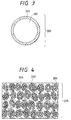
Fig. 3 is a sectional view schematically showing
one structure example of powdery material serviceable
for the positive electrode active material of a
secondary cell. In Fig. 3, the powdery material
(positive electrode active material powder) 203
comprised nickel hydroxide powder (Ni(OH)2) 201 and a
coating layer 202 higher in conductivity than nickel
hydroxide composed of at least one transition metal
other than nickel element and oxygen element.
Fig. 4 is a sectional view schematically showing
one example of an electrode member (positive electrode)
using the powdery material shown in Fig. 3. The
electrode member 205 is formed by filling a powdery
material (positive electrode active material) 203
comprising the above nickel hydroxide powder 201 coated
with the coat layer 202 higher in conductivity than
nickel hydroxide composed of a transition metal and
oxygen element into the pore portion 206 of the porous
collector 204. If necessary, the electrode member
(positive electrode) 205 can be fabricated by adding
and mixing an auxiliary conductive material, a binding
agent and a solvent to a powdery material (positive
electrode active material) 203, preparing a paste and
filling the paste into a porous collector.
Besides, the thickness of the positive electrode can be
adjusted appropriately by means of a press. With the
powdery material (positive electrode active material)
203 in the above electrode member (positive electrode)
205, the provision of the highly conductive coating
layer 202 formed on the surface of the nickel hydroxide
powder 201 increases the electronic conductivity among
the filled positive electrode active material powder
and can reduce the impedance of the electrode member
(positive electrode), thereby raising the utilizing
efficiency of charging and discharging reactions of the
positive electrode active material, i.e., increasing
the charging and discharging capacity.
Fig. 5 is a sectional view showing one example of
schematic structure of a secondary cell according to
the present invention. The secondary cell of Fig. 5 is
so constructed that a negative electrode 301 for
storing hydrogen by the charging reaction, a positive
electrode 302 comprising a positive electrode active
material mainly composed of nickel hydroxide, a
separator and an alkali hydroxide electrolyte 303 are
put in a cell housing 304 and the negative electrode
301 and the positive electrode 302 are connected to the
negative electrode terminal 305 and the positive
electrode terminal 306, as the input/output terminals.
Incidentally, when a solid electrolyte is adopted for
the electrolyte, there are cases where a separator is
not provided. With the secondary cell of Fig. 5 in the
present invention, the negative electrode and/or the
positive electrode according to the present invention
are used for both or either of the negative electrode
301 and the positive electrode 302. Thereby, it
becomes possible to fabricate a secondary cell which is
highly resistant to overcharge and high in capacity.
(Dispersion of a transition metal element onto the
surface of the hydrogen-storing alloy)
On the outermost surface of a powdery material
(e.g., material as shown in Fig. 1) comprising a
hydrogen-storing compound according to the present
invention, one transition metal element or more having
a work function of about 4.5 eV and the shortest inter-atomic
distance of 0.248 to 0.255 nm and 0.27 to 0.28
nm selected from nickel, chromium, molybdenum, copper,
palladium, platinum, iron, ruthenium, rhodium, iridium,
tungsten, titanium and manganese is dispersed. These
transition metal elements adsorb hydrogen, exhibits the
D2 (deuterium) - H2 (hydrogen) exchange reaction and
creates active hydrogen atoms easily stored by the core
of the hydrogen-storing alloy. The thickness of the
layer in which this transition metal is dispersed is
preferably not less than 1 nm and not more than
30 nm and more preferably not less than 5 nm and not
more than 10 nm so that activated atomic hydrogen
easily diffuses in the core layer. The layer thickness
can be measured by the transmission electron
microscope, the scanning Auger microanalyzer and so on.
As more concrete method for dispersing a
transition metal element onto the surface of the
hydrogen-storing compound powder (alloy) subjected to
the coating treatment by a metal oxide layer as
described below, a salt of a transition metal is
adhered to the hydrogen-storing alloy powder coated
with the metal oxide layer, then the adhered salt of
the transition metal is reduced to prepare hydrogen-storing
alloy powder coated with the metal oxide on
which the above transition metal element is dispersed.
Besides, as another concrete method, after
hydrogen-storing alloy powder coated with a metal oxide
layer is dipped into a solution of a transition metal
salt, a precipitant is reacted with the mixed solution
to deposit a compound of a transition metal on the
surface of the hydrogen-storing alloy powder coated
with the metal oxide and the deposited compound of the
transition metal is reduced to prepare hydrogen-storing
alloy powder coated with the metal oxide on which the
above transition metal element is dispersed.
As the salt of the transition metal as mentioned
above, one salt or more selected from halides,
nitrates, carbonates, organic acid salts and sulfates
can be included.
As the precipitant as mentioned above, alkali
compounds such as hydroxides and carbonates of alkali
metals, ammonium salts and amines are used and
specifically as preferred examples of compounds, one
compound or more selected from sodium hydroxide,
potassium hydroxide, lithium hydrozide, sodium
carbonate, sodium hydrogen carbonate, ammonium
carbonate and urea can be included.
The above reduction reaction is performed in the
atmosphere of a reducing gas and as the reducing gases,
one gaseous substance or more selected from hydrogen,
carbon monoxide, hydrogen iodide, hydrogen sulfide,
sulfurous acid can be included. The reduction
temperature is preferably 500°C or lower and more
preferably 350°C or lower. And, concerning the
dispersion of nickel metal element, water is added to
the hydrogen-storing compound powder and nickel
formate, the aqueous solution is dried after mixing,
nickel formate can be decomposed at about 250°C in the
hydrogen gas flow or under a vacuum to obtain the
compound powder with metal nickel dispersed on the
surface layer.
(Coating of the hydrogen-storing alloy powder with a
metal oxide layer)
With the above-mentioned hydrogen-storing (alloy)
powder, a metal oxide layer composed of one transition
metal element or more selected from molybdenum,
tungsten, vanadium, niobium, titanium, zirconium and
iridium, and oxygen element is formed. This metal
oxide layer allows active atomic hydrogen or hydrogen
ions to easily diffuse and functions to suppress the
oxidation of the core layer for storing hydrogen. Of
the oxides of the transition metals, titanium oxides
and zirconium oxides have high alkali resistance and
are preferred materials. Further, as described above,
in order to improve alkali resistance of the transition
metal oxides, they are preferably subjected to compound
oxide formation with at least one oxide selected from
oxides of aluminum and silicon. Further, the oxides of
aluminum and silicon are preferred to be amorphous in
order to allow atomic hydrogen or hydrogen ions to
easily pass the metal oxide layer.
Besides, the above-mentioned hydrogen-storing
(alloy) powder also comprises the transition metal
oxide layer composed of one transition metal element or
more selected from molybdenum, tungsten, vanadium,
niobium, titanium, zirconium and iridium, and oxygen
element formed outside the core layer for storing
hydrogen and one transition metal or more selected from
nickel, chromium, molybdenum, cobalt, copper,
palladium, platinum, iron, ruthenium, rhodium, iridium,
tungsten, titanium and manganese dispersed outside the
transition metal oxide layer.
The above transition metal oxide layer is
preferably not less than 10 nm and not more than 1µm
and more preferably not less than 20 nm and not more
than 0.5 µm so that atomic hydrogen or hydrogen ions
diffuses and easily reaches the core layer for storing
hydrogen. Besides, the above transition metal oxide
layer does not need to perfectly coat the core layer
for storing hydrogen and the above core layer is
covered with the above transition metal oxide layer
preferably in not less than 50% of the surface area and
more preferably in not less than 80%. And, as the
above transition metal oxide layer, when a hydrogen-storing
alloy according to the present invention is
employed for the negative electrode of nickel metal
hydride cell, the porous ones adsorbing or containing
water or the ones capable easily adsorbing or
containing water are preferably so that the hydrogen
generated during the charging easily diffuses into the
core layer of the hydrogen-storing alloy. Furthermore,
in order to raise the durability to the stress
breakdown due to expansion and compression in the
storage and release of hydrogen by the hydrogen-storing
alloy, the structure of the above transition metal
oxide layer is preferably amorphous or a water-contained
gel.
An examples of methods for preparing the above
transition metal oxide layer, a transition metal oxide
can be coated onto the hydrogen-storing alloy powder by
using the vacuum deposition methods and the CVD
(Chemical Vapor Deposition) methods such as electron
beam deposition, sputtering, plasma CVD, and laser
assist CVD and the spray process, but a preparing
method using the sol-gel process, ion-exchange or
chemical reaction and another preparing method
utilizing anodization or electrochemical deposition
reaction are more preferred techniques for preparing
the above transition metal oxide layer.
Besides, in the case of using a magnesium-nickel
alloy as the core layer, since an amorphous magnesium-nickel
alloy is superior in the charging and
discharging characteristics at room temperature to a
crystalline one, it is advisable to form a transition
metal oxide layer at a temperature as not allowing the
magnesium-nickel alloy to be crystallized, i.e., at
400°C or lower and preferably at 300°C or lower. As a
method for forming the above metal oxide layer on a
magnesium-nickel alloy, the plasma oxidation, plasma
CVD, laser CVD, anodization and electrochemical
deposition process can be preferably adopted. Among
these, the formation of an oxide layer by the
anodization is carried out in such a manner that after
forming on the surface of the core comprised of a
magnesium-nickel alloy, an anodizable layer of the
transition metal material by the vapor deposition, the
plating or the like, the product is dipped into an
electrolyte solution and energized with the counter
electrode being the cathode and the electrode comprised
of the magnesium-nickel alloy being employed as the
anode to form an oxide coat of the above metal. The
oxide layer formed by the above anodization is
amorphous unless subjected to a heat treatment at high
temperatures and greatly effective especially for the
inhibition of cycle deterioration in the charging and
discharging.
Various methods for coating the hydrogen-storing
powder with a tungsten oxide when selecting tungsten as
a transition metal element will be described.
Also to the preparation of hydrogen-storing alloy
powder coated with other oxide layers than the tungsten
oxide layer, ones of molybdenum, vanadium, niobium or
titanium, the method mentioned above may be applied.
In place of ammonium paratungstate in the above
(a), ammonium molybdate (NH4)6Mo7O24·4H2O, ammonium
metavanadate NH4VO3 and ammonium niobate NH4NbO3 can be
also used.
In place of sodium tungstate Na2WO4 in the above
(b), lithium tungstate Li2WO4, potassium tangstate K2WO4
sodium molybdate Na2MoO4, lithium molybdate Li2MoO4,
potassium molybdenate K2MoO4, sodium metavanadate NaVO3,
lithium vanadate LiVO3, potassium metavanadate KVO3,
sodium niobate NaNbO3, lithium niobate LiNbO3 and
potassium niobate KNbO3 can be also used.
In place of tungsten W, tungsten carbide WC or
tungsten nitride WN or W2N in the above (c), molybdenum
Mo, molybdenum carbide MoC or Mo2C, molybdenum nitride
MoN or Mo2N, vanadium V, vanadium carbide VC, vanadium
nitride VN, niobium Nb, niobium carbide NbC, niobium
nitride NbN, titanium Ti, titanium carbide TiC and
titanium nitride TiN can be also used.
Besides, as another method for coating the
hydrogen-storing alloy powder with an oxide layer of
vanadium, amorphous vanadium oxide is formed by rapidly
cooling the crystal of vanadium pentaoxide V2O5 molten
at high temperatures and dissolved in water to prepare
a sol solution and hydrogen-storing powder is dispersed
either into this sol solution or into the sol solution
prepared by flowing the molten vanadium pentaoxide into
water and allowed to stand and thereafter the hydrogen-storing
alloy powder coated with a vanadic acid gel
layer comprising oxides of vanadium can be obtained by
the separation and dry heating. This approach is
applicable also to niobium, where niobium pentaoxide
Nb2O5 is employed.
Besides, after hydrogen-storing powder is
dispersed into the sol solution prepared by the
hydrolysis, what is called sol-gel method, of alkoxide
as a compound of a transition metal and an alcohol and
the solution is allowed to stand, the hydrogen-storing
alloy powder coated with the above metal oxide layer
can be obtained by the separation and dry heating. As
the reaction for obtaining a metal oxide layer, the
hydrolysis reaction can be employed using acetyl
acetonate in place of alkoxide as the raw material.
Furthermore, after hydrogen-storing alloy powder
is dispersed into an alkoxide solution and the solution
is allowed to stand, the hydrogen-storing alloy powder
coated with the above transition metal oxide layer can
be obtained by the separation and heating, followed by
the contact with an oxygen plasma.
The examples of the alkoxide include pentaethoxy
tungsten W(OC2H5)5, pentaisopropoxy tungsten W(O-iC3H7)5,
pentaethoxy molybdenum Mo(OC2H5)5, trimothoxy vanadyl
VO(OCH3)3, tripropoxy vanadyl VO(O-n-C3H7)3, triisobutoxy
vanadyl VO(O-i-C4H9)3, tri-sec-butoxy vanadyl VO(O-sec-C4H9)3,
tri-t-butoxy vanadyl VO(O-t-C4H9)3, pentamethoxy
niobium Nb(OCH3)5, pentaethoxy niobium Nb(OC2H5)5,
pentaisopropoxy niobium Nb(O-iC3H7)5, pentaethoxy
niobium Nb(O-n-C3H7)5, pentaisobutoxy niobium Nb(O-i-C4H9)5,
pentabutoxy niobium Nb(O-n-C4H9)5, penta-sec-butoxy
niobium Nb(O-sec-C4H9)5, tetramethoxy titanium
Ti(OCH3)4, tetraethoxy titanium Ti(OC2H5)4, tetrapropoxy
titanium Ti(O-n-C3H7)4, tetraisobutopoxy titanium Ti(O-i-C4H9)4,
tetra-sec-butoxy titanium Ti(O-sec-C4H9)4,
tetra-t-butoxy titanium Ti(O-t-C4H9)4, tetramethoxy
zirconium Zr(OCH3)4, tetraethoxy zirconium Zr(OC2H5)4,
tetraisopropoxy zirconium Zr(O-n-C3H7)4, tetraisobutoxy
zirconium Zr(O-i-C4H9)4, tetra-sec-butoxy zirconium
Zr(O-sec-C4H9)4 and tetra-t-butoxy zirconium Zr(O-t-C4H9)4.
After hydrogen-storing alloy powder is dipped into
the solution of the transition metal salt as mentioned
above, precipitation occurs as a hydroxide of the
transition metal by the reaction with an alkali added
thereto, hydrogen-storing alloy powder with the
hydroxide of the transition metal deposited and adhered
is separated and the hydrogen-storing alloy powder
coated with transition metal oxides can be obtained by
dry heating.
As the method for forming a compound oxide of the
oxides of aluminum or silicon with the above-mentioned
transition metal oxide, there can be employed the sol-gel
process, the CVD method the anodization method and
the like.
(Method for preparing the hydrogen-storing powder (core
material)
As hydrogen-storing alloy powder to be used for
the core portion of a powdery material comprising a
hydrogen-storing compound according to the present
invention, the multi-component ones obtained by the
partial substitution of Ni of the MmNi5 hydrogen storing
alloy (Mm : Mischmetal) with Mn, Al and Co, transition
metal hydrogen-storing alloys of multi-component alloys
of Zr, Ti, V, Ni, Mn, Co, Fe and the like, magnesium-nickel
alloys, or the like may be included.
As methods for producing the hydrogen-storing
alloys, the high-frequency melting, arc melting, gas
atomizing method, sputtering, mechanical alloying,
molten-salt electrolysis and such other processes can
be adopted.
(Preparation of a magnesium-nickel hydrogen-storing
alloy)
In the present invention, a magnesium-nickel alloy
can be preferably employed as one of hydrogen-storing
alloys. For the preparation of such an alloy, the
following methods are included, in addition to the
mechanical alloying, mechanical grinding, gas atomizing
method, high-frequency melting, arc melting,
sputtering, molten-salt electrolysis and the like as
mentioned above.
By dipping magnesium powder into a solution
obtained by dissolving a nickel salt in a solvent,
magnesium element of higher ionization tendency can be
substituted with nickel element of lower ionization
tendency and a hydrogen-storing magnesium-nickel alloy
is prepared by a further heat treatment.
As a solvent for dissolving the above nickel salt,
alcohols such as ethyl alcohol are more suitable
because magnesium reacts with water.
As another method for preparing a magnesium-nickel
alloy, a magnesium-nickel alloy can be prepared with
the reduction of nickel hydroxide after depositing the
nickel hydride to magnesium powder.
As still another preparation method, after the
mixing of magnesium powder and nickel formate, a
nickel-magnesium alloy can be prepared by decomposing
nickel formate at about 250°C in the hydrogen flow or
under vacuum and a further heating at such a high
temperature as 400°C or so.
The magnesium-nickel alloy prepared by the above
technique is characterized in that the nickel ratio of
the surface portion is preferably higher than that of
the center portion.
Besides, a part of magnesium of the obtained
magnesium-nickel alloy can be substituted with
titanium, beryllium, aluminum, manganese, zinc,
chromium, iron, indium, cobalt, molybdenum, tin, lead,
antimony, bismuth, copper, silver, palladium or
platinum as a metal having a smaller ionization
tendency than magnesium. The substitution becomes
possible by dipping magnesium-nickel alloy powder into
a solution of a salt of the element having a smaller
ionization tendency than magnesium as mentioned above.
Needless to say, also by adding the above
substitutional element salt to the above nickel salt
solution and dipping magnesium powder in the obtained
solution to effect a chemical reaction, the magnesium-nickel
alloy powder having a part of magnesium element
substituted with an element as mentioned above can be
obtained.
With the above magnesium-nickel alloy, the element
ratio of magnesium to nickel preferably ranges from 0.8
to 2.2 to obtain a large hydrogen-storing power.
The heat treatment temperature for the preparation
of the above magnesium-nickel alloy is preferably
within a range of 100 to 600°C. Besides, the above
heat treatment step is preferably performed in the
atmosphere comprising one gas or more selected from
nitrogen gas, argon gas, helium gas and hydrogen gas or
under a reduced pressure. Furthermore, to activate the
surface, it is preferable to appropriately apply the
plasma treatment.
In addition, when the magnesium-nickel alloy
powder is caused to pass through a grinding process for
adjusting the grain size, it is preferable to grind it
in an atmosphere containing an inert gas or hydrogen
gas.
As the magnesium-nickel alloy, one made amorphous
by mixing grinding (mechanical grinding) under
application of the centrifugal force is high in
hydrogen storing power at a low temperature and
preferable.
(Fabrication of an electrode member/negative electrode)
As the preparation of an electrode member
electrode, e.g., having the structure shown in FIG. 2,
by using a powdery material comprising the above
hydrogen-storing compound, two roughly classified
methods can be employed: one by adding a auxiliary
conductive material to the powdery material and
sintering the mixture on a collector or the other by
having the powdery material bounded on a collector with
a binding agent.
As the above collector, a foamed metal obtained by
coating the surface of a sheet-shaped polymer resin
having a three dimensional network structure of foamed
urethane or the like with a metal film of nickel or the
like by the plating or other techniques and by the
decomposing removal of the resin through firing, a
foamed metal obtained by coating a felt of carbon fiber
with a metal film of nickel or the like by the plating
or other techniques, a non-woven cloth of a metal fiber
such as nickel fiber, a sintered product of nickel fine
powder, a punching metal or expanded metal of nickel or
a nickel-plated perforated thin copper sheet, a nickel
foil, a nickel-plated metal foil and such others are
employed.
As the above binding agent, a polyolefin such as
polyvinyl alcohol, polyvinyl chloride, polyethylene or
polypropylene, fluororesin such as polyvinylidene
fluoride or tetrafluoroethylene polymer, celluloses
such carboxymethylcellulose can be included.
Concerning such electrode members, especially to
reduce the impedance as a negative electrode by raising
the packing density in a negative electrode active
material layer to enhance the collecting power, at
least two powder materials of different shapes selected
from flake, circle, filament, needle, spike and such
others are employed as shapes of the auxiliary
conductive materials in the present invention.
As the above auxiliary conductive materials, one
material or more selected from a carbonaceous material
such as amorphous carbon and graphite, nickel, copper,
silver, indium and tin can be employed.
(Surface coating of nickel hydroxide powder)
In a powdery material as shown in FIG. 3, the
surface of nickel hydroxide (Ni(OH)2) powder is
preferably coated with a compound higher in
conductivity than nickel hydroxide containing one
element or more selected from lithium, potassium,
manganese, aluminum, zinc, magnesium, molybdenum,
tungsten, vanadium and titanium, higher in conductivity
than nickel hydroxide, at a ratio of 0.5 atomic % to 10
atomic % and comprising one element or more selected
from cobalt and nickel elements and oxygen element, or
a compound higher in conductivity than nickel hydroxide
comprising one element or more selected from
molybdenum, tungsten, vanadium and titanium, and oxygen
and hydrogen elements.
The compound comprising at least one element
selected from molybdenum, tungsten, vanadium and
titanium, and oxygen and hydrogen elements is
preferably made a compound oxide by addition of
aluminum and/or silicon element to improve alkali
resistance.
As specific coating methods, the following types
are included.
If coated with a compound comprising cobalt,
oxygen element and lithium, (d) as a step of coating
the surface of the nickel hydroxide powder mainly
composing the positive electrode, on dispersing nickel
hydroxide powder into a solution of a salt of one
element or more selected from lithium, potassium,
manganese, aluminum, zinc, magnesium, molybdenum,
tungsten, vanadium and titanium added to a cobalt salt
solution and then allowing the mixed solution to react
with an alkali such as lithium hydroxide and potassium
hydroxide, the nickel hydroxide powder coated with a
cobalt hydroxide compound which contains an element
selected from lithium, potassium, manganese, aluminum,
zinc, magnesium, molybdenum, tungsten, vanadium and
titanium can be prepared. As the above cobalt salts to
be reacted with, one salt or more selected from cobalt
nitrate, cobalt chloride and ammonium cobalt chloride
are included.
Substitution of a cobalt salt with a nickel salt
will provide the nickel hydroxide powder coated with
nickel hydroxide containing the additive element
mentioned above.
Also for the preparation of the hydrogen-storing
alloy powder coated with other oxides than that of
tungsten, oxides of molybdenum, vanadium, niobium and
titanium in the above methods (g) and (h), the above-mentioned
technique can be adopted.
Incidentally, in place of sodium tungstenate Na2WO4
in the above (g), lithium tungstenate Li2WO4, potassium
tungstenate K2WO4, sodium molybdenate Na2MoO4, lithium
molybdenate Li2MoO4, potassium molybdenate K2MoO4, sodium
metavanadate NaVO3, lithium metavanadate LiVO3,
potassium metavanadate KVO3, sodium niobate NaNbO3,
lithium niobate LiNbO3 and potassium niobate KNbO3 can
be also used.
In place of tungsten W and tungsten carbide WC in
the above (h), molybdenum Mo, molybdenum carbide MoC,
vanadium V, vanadium carbide VC, niobium Nb, niobium
carbide NbC, titanium Ti and titanium carbide TiC may
also be used.
Besides, as another method for coating nickel
hydroxide powder with an oxide layer of vanadium,
amorphous vanadium oxide is formed by quenching the
vanadium pentaoxide V2O5 crystal molten at high
temperatures, nickel hydroxide powder is dispersed
either into the sol solution prepared by dissolving
this into water or into the sol solution prepared by
flowing of molten vanadium pentaoxide into water and
separated and dried after the standing, the nickel
hydroxide powder covered with a vanadic acid gel layer
of oxides of vanadium can be obtained. This technique
is applicable to niobium, where niobium pentaoxide Nb2O5
is used.
To make the above nickel hydroxide coated with a
compound comprising one element or more selected from
molybdenum, tungsten and vanadium and oxygen and
hydrogen elements difficult to dissolve in the alkali
used for the electrolyte of a cell, the nickel
hydroxide powder is further coated with a compound
comprising cobalt and oxygen element, or with a
compound comprising nickel and oxygen element, or with
a compound comprising at least one element selected
from aluminum and silicon, and oxygen element, or with
a nickel metal thin film is can be adopted.
(Fabrication of electrode member/positive electrode)
The above nickel hydroxide powder subjected to the
coating treatment is mixed with a binding agent, a
solvent is added to the mixture to prepare a slurry and
the slurry is filled into a porous collector, or the
nickel hydroxide powder is bunded directly to a
collector by using a binding agent, with the result
that an electrode member employed as the positive
electrode in a secondary cell is fabricated.
The collector serves to efficiently supply the
current consumed or to collect the current generated in
the electrode reactions during the charging and
discharging. Thus, as the material forming the
collector, one which is high in conductivity and
inactive to the cell reaction is desirable.
As the above porous collector, a foam metal
obtained by coating the surface of a sheet-shaped
polymer resin having a three dimensional network
structure of foam urethane or the like with a metal
film of nickel or the like by the plating or other
techniques and by the decomposing removal of the resin
through firing, a foam metal obtained by coating a felt
of carbon fiber with a metal film of nickel or the like
by the plating or other techniques, a non-woven cloth
of a metal fiber such as nickel fiber, a sintered
product of nickel fine powder, a punching metal or
expanded metal of nickel or a nickel-plated perforated
thin copper sheet, a nickel foil, a nickel-plated metal
foil and such others are employed.
As the above binding agent, a polyolefin such as
polyvinyl alcohol, polyvinyl chloride, polyethylene or
polypropylene, fluoro resin such as polyvinylidene
fluoride or tetrafluoroethylene polymer, celluloses
such as carboxyl methyl cellulose and such others are
included.
Besides, after the slurry prepared by mixing
nickel powder and a binding agent solution is applied
to a nickel-plated, perforated copper sheet without use
of a powdery material serving as the positive electrode
active material according to the present invention, a
sintered nickel substrate obtained by the sintering is
dipped into a nickel salt solution to fill a nickel
salt and is allowed to react with an alkali solution to
form nickel hydroxide in accordance with a conventional
technique and then by combining a positive electrode
made of the sintered nickel substrate having nickel
hydroxide packed therein with a negative electrode
using the powdery material according to the first
aspect of the present invention, a secondary cell
according to the present invention can be constructed.
As mentioned above, nickel (II) nickel (III)
hydroxide Ni3O2(OH)4 is preferably mixed with the above
nickel hydroxide (Ni(OH)2) powder to form an electrode
member (positive electrode). Since nickel (II) nickel
(III) hydroxide Ni3O2(OH)4 is smaller in density than
nickel hydroxide (Ni(OH)2), too great a mix amount would
lead to a decrease in the amount of the active material
packed in the positive electrode and accordingly the
mix amount preferably ranges from 1 % by weight to 30 %
by weight and more preferably ranges from 2 % by weight
to 20 % by weight. In the alkali secondary cell using
the electrode member formed by mixing nickel (II)
nickel (III) hydroxide Ni3O2(OH)4 with nickel hydroxide
(Ni(OH)2) as the positive electrode, hydrogen atoms are
added to nickel (II) nickel (III) hydroxide Ni3O2(OH)4
having higher valent nickel atoms and nickel atoms are
reduced to lower valent nickel atoms during the
discharging. Thus, by using a positive electrode
having the above nickel (II) nickel (III) hydroxide
added, a secondary cell larger in capacity can be
obtained than an alkali secondary cell using the
positive electrode formed of nickel hydroxide Ni(OH)2
having only divalent nickel element as only a single
active material.
As one example of method for preparing nickel (II)
nickel (III) hydroxide, a preparing method by allowing
an aqueous solution of nickel nitrate to react with
bromine and an alkali hydroxide is included. Other
examples include a preparing method by mixing an alkali
peroxide and an alkali hydroxide with metal nickel,
allowing the reaction to proceed at a temperature of
about 600°C and washing the product with ice water.
(Shapes and structures of a battery)
A secondary cell according to the present
invention is, for example, flat, cylindrical,
rectangular parallelepiped (box-type), sheet-shaped or
the like. Its structure is single-layered, multi-layered,
spiral or the like. Above all, a spiral-structured
cylindrical cell is characterized in that
the electrode area can be increased by interposing a
separator between the negative electrode and the
positive electrode and rolling in the electrodes and a
large current can flow during the charging and
discharging. And, rectangular parallelepiped and
sheet-shaped cells are characterized in that an
effective use can be made of the admission space of
devices for housing a cell.
Hereinafter, referring to FIGS. 6, 7 and 8,
practical examples of cells in shape and structure will
be described in more detail. FIG. 6 is a sectional
view of a single-layered flat (coin-shaped) cell, FIG.
7 is a sectional view of a spiral-structured
cylindrical cell and FIG. 8 is a sectional view of a
rectangular parallelepiped cell. These secondary cells
are basically similar in construction to that of FIG. 5
and comprises a negative electrode, a positive
electrode, an electrode/separator, a battery housing,
output terminals and so on.
In FIGS. 6, 7 and 8, Numerals 401, 503 and 601
denote negative electrodes comprising a negative
electrode active material layer Numerals 403, 506 and
603 denote positive electrodes comprising a positive
electrode active material layer; Numerals 405, 508 and
605 denote negative electrode terminals (negative
electrode caps or negative electrode cans); Numerals
406, 509 and 606 denote positive electrode terminals
(positive electrode caps or positive electrode cans);
Numerals 407, 507 and 607 denote separators.
electrolytes; Numerals 410 and 510 denote gaskets;
Numerals 501 and 600 denote negative electrode
collectors; Numerals 504 and 511 denote a positive
electrode collector and an insulating plate; Numerals
512 and 513 denote a negative electrode lead wire and a
positive electrode wire; Numerals 514 and 614 denote
safety valves; and Numeral 609 denotes a battery
housing (battery jar). With the flat (coin-shaped)
secondary cell shown in FIG. 6, a positive electrode
403 comprising a positive electrode active material
(active material layer) and a negative electrode 401
comprising a negative electrode active material (active
material layer) is stacked at least via a separator 407
retaining an electrolyte (electrolyte solution), this
stack is housed in a positive electrode can 406 as the
positive electrode terminal from the positive electrode
side and the negative electrode side is coated with a
negative electrode cap 405 as the negative electrode
terminal. And, a gasket 410 is disposed at another
part in the positive electrode can 406. With the
cylindrical lithium secondary cell shown in FIG. 7, a
positive electrode 506 comprising a positive electrode
active material layer (active material layer) 505
formed on a positive electrode collector 504 and a
negative electrode 503 comprising a negative electrode
active material layer (active material layer) 502
formed on a negative electrode collector 501 sandwich
at least a separator 507 retaining an electrolyte
(electrolyte solution) between themselves and the
spiral-structured stack wound at multiple times around
a predetermined axis is housed in a negative electrode
can 508 from its the lateral side and one base side.
Besides, the other base (top) side is covered with a
positive electrode terminal (positive electrode cap)
509. And at the other part in the negative electrode
can, an insulator (gasket 510) is disposed. The
spiral-structured electrode stack is isolated from the
positive electrode cap 509 side via an insulating plate
511. The negative electrode 503 is connected via a
negative electrode lead wire 512 to the negative
electrode can 508, whereas the positive electrode 506
is connected via a positive electrode lead wire 513 to
the positive electrode cap 509. On the positive
electrode cap side 509, a safety valve 514 for
adjusting the internal pressure inside the battery is
provided.
Hereinafter, one example of method for assembling
the batteries shown in FIGS. 6 and 7 will be described.
Incidentally, the material preparation and the
assembling of the above secondary cell are desirably
performed in dry air from which moisture is removed
sufficiently or in a dry inertia gas.
With the example of rectangular parallelepiped
battery shown in FIG. 8, a plurality of unit cells each
comprising a negative electrode 601/a separator
containing an electrolyte (electrolyte solution) 607/ a
positive electrode 603 are stacked via separators,
connected in parallel and housed in a battery housing
(battery case) 609. The negative electrode 601 and the
positive electrode 603 are connected to a negative
electrode terminal 605 and to a positive electrode
terminal 606, respectively. Furthermore, in the
battery housing 609, a safety valve 614 for adjusting
the internal pressure is provided.
Hereinafter, one example of method for assembling
the battery shown in FIG. 8 will be described.
Next, the arrangement of members in the above-mentioned
examples of secondary cells will be
described.
(Electrolyte)
With secondary cells using the electrode member as
mentioned above, the electrolyte solution made by
dissolving an electrolyte into a solvent is used while
allowing it to be retained in a porous separator.
The conductivity of the electrolyte is required to
be preferably not less than 1 × 10⁻³ S/cm and more
preferably not less than 5 × 10⁻³ S/cm at 25°C.
As the electrolyte, potassium hydroxide, lithium
hydroxide, sodium hydroxide and their mixtured salts
are included. Generally, an aqueous alkaline solution
made by dissolving the above electrolyte into water are
used as the electrolyte solution.
To prevent the leakage of the above electrolyte
solution, their gelification is preferable. As the
gelifying agent, those polymers which absorb the
solvent of the electrolyte to swell are desirably used.
As such polymers, polyethylene oxide, polyvinyl
alcohol, polyacryl amide and the like are employed.
(Separator)
The separator used in a secondary cell according
to the present invention serve to prevent the short-circuit
between a negative electrode and a positive
electrode. Besides, they may serve to hold an
electrolyte solution.
The separator is required to have pores through
which hydrogen ions can move and to be insoluble and
stable in an electrolyte solution. Accordingly, as the
separator, for example, non-woven cloth of glass,
polyolefin such as polypropylene or polyethylene,
fluororesin, polyimide or the like or micropore-structured
materials are appropriately employed. The
separators of the materials such as polyolefin or
fluororesin as mentioned above are preferably
hydrophilified to raise the wettability to an
electrolyte solution. The hydrophilification treatment
can be simply accomplished with a treatment by the
irradiation of a plasma such as hydrogen plasma, oxygen
plasma and fluorine plasma, an ozone irradiation
treatment, a corona discharge treatment, or a treatment
by chemicals.
Besides, a metal oxide film having pores or a
resin film made composite with a metal oxide may be
employed.
(Battery housing (battery jar))
As the housing (battery jar) of an alkali
secondary battery according to the present invention in
a case where the output/input terminals of the battery
serves also as the battery housing (battery jar), that
is, as the materials of the members 405, 406, 508 and
509 of the cells shown in Figs, 6 and 7, a copper sheet
or a stainless steel sheet is appropriately employed.
Especially, a titanium-clad stainless steel sheet, a
copper-clad stainless steel sheet, a nickel-plated
copper sheet or the like is frequently employed.
In the case of the battery housing (jar) 609 shown
in FIG. 8 where the input/output terminals of a battery
does not serve also as the battery housing, examples of
the materials for such a battery housing (jar) include
not only a stainless steel but also a metal such as
zinc, plastic such as polypropyrene or a composite
material of metal or glass fibers with plastics.
(Safety valve)
As safety measures for the time of elevated
internal pressure of a battery, a safety valve (514,
614) is provided in a secondary cell according to the
present invention. As a safety valve, for examples,
rubber, a spring, a metal ball, a rupture foil or the
like is employed.
(Gasket)
As members of gaskets (410, 510) in the present
invention, for example, fluorine resin, polyamide
resin, polysulfone resin or various types of rubbers
may be employed. As a sealing method of batteries, not
only 'caulking ' using a gasket as shown in FIGS. 6 and
7 but also a method using a tube sealing with glass, an
adhesive, welding, soldering or the like is employed.
Besides, as the material for the insulating plate
of the structure shown in FIG. 7, various organic resin
materials or ceramics are employed.
Hereinafter, referring to Examples, the present
invention will be described in detail. Incidentally,
the present invention is not limited to these examples.
Methods for preparing a powdery material
comprising a hydrogen-storing compound of a negative
electrode active material serving as the main material
of the negative electrode of a secondary cell, methods
for forming an electrode member (negative electrode)
according to the present invention, surface treatment
methods of a powdery material employed as a positive
electrode active material serving as the main material
of the positive electrode of a secondary cell, methods
for forming an electrode member (positive electrode)
according to the present invention and the preparation
of a secondary cell according to the present invention
are described referring to the respective examples in
Examples 1 to 4, in Examples 5 to 10, in Examples 11 to
15, in Examples 16 to 20 and in Examples 21 to 38.
Incidentally, in these examples and comparative
examples, AA-sized cylindrical batteries similar to
that shown in FIG. 7 were prepared.
[Preparation of Hydrogen-Storing Alloy Powder]
(Example 1)
(1) Preparation of hydrogen-storing alloy powder
employed as the core:
Magnesium powder of not greater than 80 mesh size
was dipped into an ethanol solution containing nickel
chloride dissolved so as to attain a ratio of nickel
element to magnesium element of 1:1 and further
containing cobalt chloride and cupric chloride
dissolved so as to attain 2 atomic % and 1 atomic %
with regard to magnesium element and a reaction was
allowed to proceed at 50°C under irradiation of
ultrasonic waves of 37 kHz with an ultrasonic cleaner
to replace magnesium element in the magnesium powder
with nickel, cobalt and copper elements. By treating
the obtained powder at 350°C in a hydrogen gas flow,
the magnesium-nickel alloy powder containing traces of
cobalt element and copper element was obtained.
As a result of a quantitative analysis of the
nickel element in the depth direction with argon
etching using the scanning Auger microanalyzer of the
thus obtained magnesium-nickel alloy powder and of the
averaged elemental ratios of magnesium element to
nickel element as estimated by the plasma emission
spectroscopy of the above magnesium-nickel alloy
powder, it was found that the ratio of nickel element
was higher in the surface than in the center portion.
(2) Coating of hydrogen-storing alloy powder with
a metal oxide:
i) Titanium powder of not greater than 100 mesh
size was added little by little to aqueous hydrogen
peroxide cooled with ice and allowed to react
therewith, and after the completion of reaction, the
remaining hydrogen peroxide was decomposed by using a
platinum mesh to prepare an aqueous solution of
peroxopolytitanic acid. The magnesium-nickel alloy
powder as obtained in the above (1) was dispersed into
the above obtained peroxopolytitanic acid solution and
allowed to stand for 30 minutes. After separation, the
product was washed with cool water and heat-treated at
150°C after drying. By this, magnesium-nickel alloy
powder coated with a peroxopolytitanic acid film (film
thickness: 0.5 µm) as a composed of titanium and oxygen
element was obtained.
ii) Next, after the compound powder obtained in
the i) was dispersed into an aqueous solution of nickel
chloride and cobalt chloride, the solution was stirred
so that the powder adsorbed nickel chloride and cobalt
chloride. The powder was separated and dispersed into
an aqueous solution of sodium hydroxide to react the
nickel chloride and cobalt chloride adsorbed to the
surface of the peroxopolytitanic acid film with the
sodium hydrixude, thereby depositing nickel hydroxide
and cobalt hydroxide. After water washing and drying,
the nickel hydroxide-cobalt hydroxide was reduced by
the heat treatment in a hydrogen gas flow at 300°C to
obtain compound powder comprising a core of a
magnesium-nickel alloy coated with a compound of
titanium and oxygen element and having metallic nickel
and cobalt dispersed and carried on the outermost
surface in a thickness of about 30 nm.
On the analysis of the compound powder obtained in
ii) by the scanning Auger microanalyzer, it was
confirmed that the compound powder was almost coated
with titanium and oxygen element and that nickel and
cobalt elements were dispersed on the outermost
surface.
(Example 2)
(1) Preparation of hydrogen-storing alloy powder
employed as the core:
Magnesium powder of not greater than 80 mesh size
was mixed with nickel powder not greater than 1 µm in
average particle size so as to attain the elemental
ratio of 1:1 relative to the magnesium element and the
mixture was ground by using a planetary ball mill for
20 hours to obtain magnesium-nickel alloy powder. (The
obtained alloy was confirmed to be amorphous using the
X-ray diffraction analysis.) The obtained powder was
treated at 100°C in a hydrogen gas flow.
(2) Coating of hydrogen-storing alloy powder with
a metal oxide:
i) Aqueous hydrogen peroxide was allowed to react
with molybdenum carbide powder of not greater than 100
mesh size, and after the completion of the reaction,
the remaining hydrogen peroxide was decomposed by using
a platinum mesh to prepare an aqueous solution of
peroxopolymolybdic acid. To this was added a sol
solution prepared by dissolving aluminum nitrate in
1,3-butanediol and heating to 90°C and the magnesium-nickel
alloy powder obtained in the above (1) was
dispersed into this solution. After standing and
separation, the product was washed with cool water and
was heat-treated at 150°C after the drying. By this,
the product comprising a core of magnesium-nickel alloy
coated with a compound of molybdenum, aluminum and
oxygen element was obtained.
ii) Next, the compound powder obtained in the i)
was dispersed into an aqueous solution of nickel
formate and mixed. After the drying, the nickel
formate was decomposed by the treatment in a hydrogen
gas flow at 250°C to obtain the compound powder
comprising a core of a magnesium-nickel alloy coated
with a compound of molybdenum, carbon and oxygen
element and having metallic nickel dispersed and
carried on the outermost surface in a thickness of
about 10 nm.
On the analysis by the scanning Auger
microanalyzer, it was confirmed that the compound
powder obtained in ii) was almost coated with tungsten
and oxygen elements and nickel element was dispersed on
the outermost surface.
(Example 3)
(1) Preparation of hydrogen-storing alloy powder
employed as the core:
In order that a Mischmetal (Mm) alloy
MmNi3.6MnO.4AlO.3CoO.7 could be obtained, misch metal
powder having the composition of La (30%), Ce (40%), Pr
(4%), Nd (14%), and Fe (5%), nickel powder, manganese
powder, aluminum powder and cobalt powder were mixed.
The mixture was then melted by a high frequency furnace
in an atmosphere of argon gas to prepare an alloy. The
obtained alloy was ground in an atmosphere of argon gas
to obtain alloy powder not greater than 20 µm in
average particle size.
(2) Coating of hydrogen-storing alloy powder with a
metal oxide:
i) The hydrogen-storing alloy powder prepared in
the above (1) was dipped in an ethanol solution of
tetra-n-propoxy titanium and ethoxy lithium dissolved
at a molar ratio of 10:1. After separation, the powder
was subjected to dry hydrolysis in air and heat-treated
at 250°C. Thereby, the product comprising a core of
hydrogen-storing alloy coated with a film of a compound
(titanium oxide) of titanium and oxygen element
containing lithium was obtained.
ii) Next, the compound powder obtained in the i)
was dipped into an ethanol solution of molybdenum
dichloride so that molybdenum dichloride could be
adsorbed to the powder and then separated and dispersed
into an ethanol solution of sodium hydroxide to react
the molybdenum chloride adsorbed to the surface of the
titanium oxide film with the sodium hydroxide to
deposit molybdenum oxide. After water washing and
drying, the molybdenum oxide was reduced by the
treatment in a hydrogen gas flow at 400°C to obtain the
compound powder comprising a core of the hydrogen-storing
alloy of the above (1) coated with titanium
oxide (thickness: 50 nm) containing lithium element and
having metallic molybdenum dispersed and carried on the
outermost surface in a thickness of about 5 nm.
On the analysis by the scanning Auger
microanalyzer, it was confirmed that the compound
powder obtained in ii) was almost coated with titanium
element and oxygen element and that metallic molybdenum
element were dispersed on the outermost surface.
(Example 4)
(1) Preparation of hydrogen-storing alloy powder
employed as the core:
In order that a transition metal alloy
ZrO.9TiO.1Ni1.1CoO.1MnO.6VO.2 was obtained, zirconium
powder, titanium powder, nickel powder, cobalt powder,
manganese powder and vanadium powder having the above
compositional ratio were mixed and then melted by means
of an arc in the atmosphere of argon gas to prepare the
alloy. After the heat treatment at 1100°C under
vacuum, the obtained alloy was ground in the atmosphere
of argon gas to thus obtain alloy powder not greater
than 50 µm in average particle size.
(2) Coating of hydrogen-storing powder with a metal
oxide:
i) After a silica sol solution prepared by the
sol-gel process using tetraethoxysilane as the starting
material was added to an aqueous solution of ammonium
paratungstate and lithium hydroxide dissolved at a
molar ratio of 10:1, the hydrogen-storing alloy powder
prepared in the above (1) was dipped and heat-treated
at 600°C in a hydrogen gas flow to thus obtain the
hydrogen-storing alloy powder having the surface coated
with a tungsten-silicon oxide layer containing lithium
(layer thickness: 0.1 µm).
ii) Next, the compound powder obtained in the i)
was dipped into an aqueous solution of nickel nitrate,
cobalt nitrate and copper nitrate dissolved at a molar
ratio of 3:2:5, separated and dispersed into an aqueous
solution of sodium hydroxide to react the nickel
nitrate, cobalt nitrate and copper nitrate adsorbed to
the surface of the tungsten oxide film with the sodium
hydroxide, thereby depositing hydroxides comprising
nickel hydroxide, cobalt hydroxide and copper
hydroxide. After water washing and drying, the
hydroxides were reduced by the treatment in the
hydrogen gas flow at 180°C to thus obtain the compound
powder comprising a core of the hydrogen-storing alloy
of the above (1) coated with lithium-contained tungsten
-silicon oxide containing lithium element and having
metallic nickel, cobalt and copper dispersed and
carried on the outermost surface in a thickness of
about 10 nm.
On the analysis by the scanning Auger
microanalyzer, it was confirmed that the compound
powder obtained in ii) was almost coated with tungsten
element and oxygen element and that metallic nickel,
cobalt and copper element were dispersed on the
outermost surface.
Comparative analysis of the hydrogen-storing alloy
powder employed in the core layer of Examples 1, 2, 3
and 4 (powder not coated with an oxide layer and having
no metal element dispersed) and the hydrogen-storing
compound powder obtained in Examples 1, 2, 3 and 4 by
the gas chromatography concerning the ratio of
hydrogendeuterium (HD) separately generated by the
hydrogen-deuterium exchange reaction in the 1:1
atmosphere of hydrogen (H2) and deuterium (D2) at less
than 1 atm reveals that the compound powder obtained in
the Examples each generates a greater amount of
hydrogendeuterium than the alloy powder having no
coating layer and dispersed metal and was therefore
larger in the activity of the hydrogen-deuterium
exchange reaction. This suggests that the compound
powder obtained in the examples is more likely to
generate atomic hydrogen.
[Formation of Electrode Members (Negative Electrode)]
(Example 5)
The hydrogen-storing compound powder obtained in
Example 1 was mixed with 2 weight ratio of flake-like
nickel powder, 15-20 µm in average particle size, 0.8
weight ratio of spiky nickel powder, 3-7 µm in average
particle size, and 0.2 weight ratio of filament-shaped
nickel powder, 0.8 µm in average particle size as the
auxiliary conductive materials, and 3 % by weight of
polyvinyl alcohol on the compound powder basis under
the addition of water to prepare a pasty mixture and
the mixture was filled in a spongy nickel porous member
of 95% porosity having an average pore size of 150 µm.
After drying, the filled member was pressurized by
using a roller press and cut to a predetermined size.
To the cut member, a nickel lead wire was connected by
the spot welding and an electrode member serving as the
negative electrode of a secondary cell was obtained.
(Example 6)
The hydrogen-storing compound powder obtained in
Example 2 was mixed with 2 weight ratio of flake-like
nickel powder, 15-20 µm in average particle size, 0.8
weight ratio of spiky nickel powder, 3-7 µm in average
particle size, 0.2 weight ratio of filament-shaped
nickel powder, 0.8 µm in average particle size as the
auxiliary conductive materials, and 3 % by weight of
polyvinyl alcohol on the compound powder basis under
the addition of water to prepare a pasty mixture and
the mixture was applied to a nickel-plated steel sheet
of punching metal and shaped. After drying, the shaped
sheet was pressurized by using a roller press and cut
to a predetermined size. To the cut member, a nickel
lead wire was connected and an electrode member serving
as the negative electrode of a secondary cell was
obtained.
(Example 7)
The hydrogen-storing compound powder obtained in
Example 3 was mixed with 2 weight ratio of flake-like
nickel powder, 15-20 µm in average particle size, 1
weight ratio of spherical copper powder, 1 µm in
average particle size as the auxiliary conductive
materials, and 3 % by weight of polyvinyl alcohol on
the compound powder basis under the addition of water
to prepare a pasty mixture and the mixture was applied
to a nickel-plated steel sheet of punching metal and
shaped. After drying, the shaped sheet was pressurized
by using a roller press and cut to a predetermined
size. To the cut member, a nickel lead wire was
connected and an electrode member serving as the
negative electrode of a secondary cell was obtained.
(Example 8)
The hydrogen-storing compound powder obtained in
Example 4 was mixed with 2 weight ratio of flake-like
nickel coated graphite powder, 85 µm in average
particle size, 1 weight ratio of spherical nickel
powder, 10 µm in average particle size as the auxiliary
conductive materials, and 3 % by weight of polyvinyl
alcohol on the compound powder basis under the addition
of water to prepare a pasty mixture and the mixture was
filled in a spongy nickel porous member having a
porosity of 95% and an average pore size of 150 µm.
After drying, the filled member was pressurized by
using a roller press and cut to a predetermined size.
To the cut member, a nickel lead wire was connected and
an electrode member serving as the negative electrode
of a secondary cell was obtained.
(Example 9)
The hydrogen-storing compound powder obtained in
Example 4 was mixed with 2 weight ratio of flake-like
nickel powder, 15-20 µm in average particle size and 1
weight ratio of spherical copper powder, 1 µm in
average particle size as the auxiliary conductive
materials on the cmpound powder basis, and the mixture
was shaped to a nickel-plated steel sheet of punching
metal under pressure. The sheet was sintered in the
argon gas flow and cut to a predetermined size. To the
cut member, a nickel lead wire was connected and an
electrode member serving as the negative electrode of a
secondary cell was obtained.
(Example 10)
The hydrogen-storing compound powder obtained in
Example 2 was mixed with 3 weight ratio of flake-like
nickel powder, 15-20 µm in average particle size as the
auxiliary conductive material, and 3 % by weight of
polyvinyl alcohol on the compound powder basis under
the addition of water to prepare a pasty mixture and
the mixture was applied to a nickel-plated steel sheet
of punching metal and shaped. After drying, the shaped
sheet was pressurized by using a roller press and cut
to a predetermined size. To the cut member, a nickel
lead wire was connected and an electrode member serving
as the negative electrode of a secondary cell was
obtained.
(Comparative Example 1)
Without carrying out the coating by oxide
treatment and the transition metal element dispersion
treatment as carried out in Example 1, magnesium powder
and nickel powder were mixed at a molar ratio of 1:1 in
an atmosphere of argon gas and the mixture was put in a
graphite crucible of a high frequency melting furnace
and melted in an argon gas atmosphere to obtain a
hydrogen-storing alloy powder. Using the hydrogen-storing
alloy powder obtained by the high-frequency
melting as such, it was mixed with 3 weight ratio of
flake-like nickel powder, 15-20 µm in average particle
size as the auxiliary conductive material and 3 % by
weight of polyvinyl alcohol on the alloy powder basis
under the addition of water to prepare a pasty mixture
and the mixture was filled in a spongy nickel porous
member having a porosity of 95% and an average pore
size of 150 µm. After drying, the filled member was
pressurized by using a roller press and cut to a
predetermined size. To the cut member, a nickel lead
wire was connected by the spot welding and an electrode
member serving as the negative electrode of a secondary
cell was obtained.
(Comparative Example 2)
Without carrying out the coating by oxide
treatment and the transition metal element dispersion
treatment as carried out in Example 2, that is, using
the hydrogen-storing alloy powder used in the core
layer as such, it was mixed with 3 weight ratio of
flake-like nickel powder, 15-20 µm in average particle
size as the auxiliary conductive material and 3 % by
weight of polyvinyl alcohol on the alloy powder basis
under the addition of water to prepare a pasty mixture,
and the mixture was applied to a nickel-plated steel
sheet of punching metal and shaped. After drying, the
shaped sheet was pressurized by using a roller press
and cut to a predetermined size. To the cut member, a
lead of nickel wire was connected and an electrode
member serving as the negative electrode was obtained.
(Comparative Example 3)
Without carrying out the coating by oxide
treatment and the transition metal element dispersion
treatment as carried out in Example 3, that is, using
the hydrogen-storing alloy powder used in the core
layer as such, it was mixed with 3 weight ratio of
flake-like nickel powder, 15-20 µm in average particle
size as the auxiliary conductive material and 3 % by
weight of polyvinyl alcohol on the alloy powder basis
under the addition of water to prepare a pasty mixture
and the mixture was applied to a nickel-plated steel
sheet of punching metal and shaped. After drying, the
shaped sheet was pressurized by using a roller press
and cut to a predetermined size. To the cut member, a
lead of nickel wire was connected and an electrode
member serving as the negative electrode was obtained.
(Comparative Example 4)
Without carrying out the coating by oxide
treatment and the transition metal element dispersion
treatment as carried out in Example 4, that is, using
the hydrogen-storing alloy powder used in the core
layer as such, it was mixed with 3 weight ratio of
flake-like nickel powder, 15-20 µm in average particle
size as the auxiliary conductive material and 3 % by
weight of polyvinyl alcohol on the alloy powder basis
under the addition of water to prepare a pasty mixture
and the mixture was filled in a spongy nickel porous
member having a porosity of 95% and an average pore
size of 150 µm. After drying, the filled member was
pressurized by using a roller press and cut to a
predetermined size. To the cut member, a lead of
nickel wire was connected and an electrode member
serving as the negative electrode was obtained.
(Comparative Example 5)
Without carrying out the coating by oxide
treatment and the transition metal element dispersion
treatment as carried out in Example 4, that is, using
the hydrogen-storing alloy powder used in the core
layer as such, it was mixed with 3 weight ratio of
flake-like nickel powder, 15-20 µm in average particle
size as the auxiliary conductive material and the
mixture was shaped to a nickel-plated steel sheet of
punching metal under pressure. The sheet was sintered
in the argon gas flow and cut to a predetermined size.
To the cut member, a lead of nickel wire was connected
and an electrode member serving as the negative
electrode was obtained.
[Preparation of Nickel Hydroxide Powder]
(Example 11)
After 0.08 part of cobalt nitrate powder, 0.02
part of nickel nitrate powder and 0.01 part of lithium
acetate powder are mixed with 1.0 part of nickel
hydroxide powder, 10 µm in average particle size in
terms of molar ratio, the mixture was gradually heated
to 120°C to obtain nickel hydroxide powder coated with
a compound composed of cobalt, nickel, oxygen and
lithium elements could be obtained.
Incidentally, the cobalt element, nickel element
and oxygen element on the surface of the nickel
hydroxide was confirmed by the elemental mapping with
the scanning Auger microanalyzer. Further, the
presence of the lithium element on the surface of the
nickel hydroxide was confirmed by the plasma emission
spectroscopy of an aqueous solution of the powdery
material as separately obtained dissolved in
hydrochloric acid.
Besides, in the state that the nickel hydroxide
powder subjected to the above surface treatment and the
nickel hydroxide powder not subjected to the above
surface treatment (904) was separately filled between
the parallel plate electrodes (901 and 902) shown in
FIG. 9 and laterally fixed by insulators 903, the
resistance between the electrodes was measured by means
of a measuring device 905 under application of a
predetermined pressure as shown by the arrow in the
same figure to compare the effects of various surface
treatments. As compared with the powder not subjected
to the surface treatment, the resistance value was
clearly reduced in the nickel hydroxide powder
subjected to the surface treatment.
(Example 12)
After 0.1 part of cobalt nitrate powder and 0.01
part of lithium citrate powder are mixed with 1.0 part
of nickel hydroxide powder, 10 µm in average particle
size in terms of molar ratio, the mixture was gradually
heated to 120°C to obtain the nickel hydroxide powder
coated with a compound composed of cobalt, oxygen and
lithium elements.
Incidentally, the cobalt element and oxygen
element on the surface of the nickel hydroxide was
confirmed by the scanning Auger. Further, the presence
of the lithium element on the surface of the nickel
hydroxide was confirmed by the plasma emission
spectroscopy of an aqueous solution of the powdery
material as separately obtained dissolved in
hydrochloric acid.
Besides, following the same procedure as in
Example 11, in the state that the nickel hydroxide
powder subjected to the surface treatment and the
nickel hydroxide powder not subjected to the surface
treatment was separately filled between the parallel
plate electrodes (901, 902) shown in FIG. 9 and the
resistance between the electrodes was measured under
application of a predetermined pressure to compare the
effects of various surface treatments. As compared
with the surface-untreated case, the resistance value
was clearly reduced in the surface-treated nickel
hydroxide powder.
(Example 13)
Into a saturated solution of cobalt hydroxide
dissolved in aqueous ammonium, 10 times the cobalt
hydroxide amount of nickel hydroxide powder in terms of
molar ratio was dipped, and potassium hydroxide was
added, thereafter the mixture was boiled, whereby
nickel hydroxide powder coated with potassium
hydroxocobaltate (II) composed of cobalt, oxygen,
hydrogen and potassium elements could be obtained.
Incidentally, the cobalt element and oxygen
element on the surface of the obtained nickel hydroxide
powder was confirmed by the scanning Auger
microanalyzer. Further, the presence of the potassium
element on the surface of the nickel hydroxide was
confirmed by the plasma emission spectroscopy of an
aqueous solution of the powdery material as separately
obtained dissolved in hydrochloric acid.
Besides, following the same procedure as in
Example 11, the nickel hydroxide powder subjected to
the surface treatment and the nickel hydroxide powder
not subjected to the above surface treatment was
separately filled between the parallel plate electrodes
(901, 902) shown in FIG. 9, the resistance between the
electrodes was measured under application of a
predetermined pressure to compare the effects of
various surface treatments. As compared with the
surface-untreated case, the resistance value was
clearly reduced in the surface-treated nickel hydroxide
powder.
(Example 14)
Into a solution of 1 part of cobalt nitrate, 0.05
part of zinc nitrate and 0.5 part of bromine dissolved
in water, 10 times the cobalt nitrate amount of nickel
hydroxide powder, 10 µm in average particle size, was
dispersed in terms of molar ratio, and an aqueous
solution of 3 times the cobalt nitrate amount of
potassium hydroxide was added dropwise with stirring.
After standing, the produced precipitation was washed
with water free from carbon dioxide with decantation
and filtration and dried under a reduced pressure to
obtain nickel hydroxide powder coated with a compound
composed of cobalt and oxygen elements.
Incidentally, the cobalt element and oxygen
element on the surface of the obtained nickel hydroxide
was confirmed by the scanning Auger microanalyzer,
while the zinc element on the surface of the nickel
hydroxide powder was confirmed by the plasma emission
spectroscopy of an aqueous solution of the powdery
material as separately obtained dissolved in
hydrochloric acid.
Besides, following the same procedure as in
Example 11, the nickel hydroxide powder subjected to
the surface treatment and the nickel hydroxide powder
not subjected to the surface treatment was separately
filled between the parallel plate electrodes (901, 902)
shown in FIG. 9, the resistance between the electrodes
was measured under application of a predetermined
pressure to compare the effects of various surface
treatments. As compared with the surface-untreated
case, the resistance value was clearly reduced in the
surface-treated nickel hydroxide powder.
(Example 15)
After nickel hydroxide powder, 10 µm in average
particle size was dipped into an ethanol solution of
pentaethoxy molybdenum, ethoxy silane and ethoxy
lithium dissolved at a molar ratio of 1:0.5;0.1, the
powder was separated. Then, the pentaethoxy molybdenum
and ethoxy silane were hydrolysed in the air, and the
mixture was heat-treated at 150°C to obtain nickel
hydroxide powder coated with a compound composed of
molybdenum, silicon and oxygen elements containing
lithium element.
Incidentally, the molybdenum, silicon and oxygen
elements on the surface of the nickel hydroxide powder
was confirmed by the scanning Auger microanalyzer,
while the presence of the lithium element on the
surface of the nickel hydroxide powder was confirmed by
the plasma emission spectroscopy of an aqueous solution
of the powdery material as separately obtained
dissolved in hydrochloric acid.
Besides, following the same procedure as in
Example 11, the nickel hydroxide powder subjected to
the surface treatment or the nickel hydroxide powder
not subjected to the surface treatment was separately
filled between the parallel plate electrodes (901, 902)
shown in FIG. 9 and the resistance between the
electrodes was measured under application of a
predetermined pressure to compare the effects of
various surface treatments. As compared with the
surface-untreated case, the resistance value was
clearly reduced in the surface-treated nickel hydroxide
powder.
[Formation of Positive Electrode]
(Example 16)
After 90% by weight of the surface-coated nickel
hydroxide (Ni(OH)2) powder obtained in Example 11, 8% by
weight of nickel (II) nickel (III) hydroxide Ni3O2(OH)4
and 2% by weight of carboxymethylcellulose as a binding
agent were mixed with each other, water was added to
the mixture to obtain a paste. The paste was filled in
and applied to a 1.5mm thick foamed nickel substrate of
95% porosity having a pore diameter of 200 µm and was
then dried at 120°C for an hour. The obtained member
was pressed to be adjusted in the thickness thereof.
Next, the pressed member was cut to a predetermined
size, a lead of nickel wire was connected thereto by
the spot welding to obtain an electrode member serving
as the positive electrode of a secondary cell.
Incidentally, the above nickel (II) nickel (III)
hydroxide Ni3O2(OH)4 was obtained by adding dropwise an
aqueous solution of lithium hydroxide to an aqueous
solution of nickel nitrate and bromine with stirring,
followed by precipitation, separation and drying.
(Example 17)
Using the surface-coated nickel hydroxide powder
obtained in Example 12, an electrode member forming the
positive electrode of a secondary cell was prepared by
following the same procedure as in Example 16.
(Example 18)
Using the surface-coated nickel hydroxide powder
obtained in Example 13, an electrode member forming the
positive electrode was prepared by following the same
procedure as in Example 16.
(Example 19)
Using the surface-coated nickel hydroxide powder
obtained in Example 14, an electrode member forming the
positive electrode was prepared by following the same
procedure as in Example 16.
(Example 20)
Using the surface-coated nickel hydroxide powder
obtained in Example 15, an electrode member forming the
positive electrode was prepared by following the same
procedure as in Example 16.
(Comparative Example 6)
After the mixing of 92% by weight of nickel
hydroxide powder and 2% by weight of cobalt oxide
powder, an aqueous solution of 2% by weight of
carboxymethylcellulose was added as a binding agent to
thus obtain a paste. This paste was filled in and
applied to a 1.5mm thick foamed nickel substrate of 95%
porosity having a pore diameter of 200 µm and dried at
120°C for an hour. The obtained member was pressed to
be adjusted in thickness. Next, the pressed member was
cut to a predetermined size, a lead of nickel wire was
connected thereto by the spot welding to obtain an
electrode member forming the positive electrode.
[Preparation of Electrolyte Solution]
An aqueous solution of 6M (mol/l) potassium
hydroxide and 1M (mol/l) lithium hydroxide was
prepared.
[Provision of Separator]
A hydrophilified polypropylene unwoven cloth was
employed.
[Preparation of Battery]
[Battery Using an Electrode Member (Negative Electrode)
According to the Present Invention]
(Example 21)
A group of electrodes were produced by winding the
negative electrode obtained in Example 5 and the
positive electrode obtained in Comparative Example 6
via an interposed separator in a cylindrical spiral
shape. After inserting the electrodes into an
electrode can, lead wires were welded to the portions
forming the input/output terminals of the battery can
and the battery cap. Then, the electrolyte solution
was injected and sealing was effected by caulking to
make a closed battery.
Incidentally, the battery was a positive
electrode-capacity regulated battery having a positive
electrode larger in capacity than a negative electrode.
(Example 22)
Using the negative electrode obtained in Example 6
and the positive electrode obtained in Comparative
Example 6, a positive electrode-capacity regulated
closed battery was fabricated by following the same
procedure as in Example 21.
(Example 23)
Using the negative electrode obtained in Example 7
and the positive electrode obtained in Comparative
Example 6, a positive electrode-capacity regulated
closed battery was fabricated by following the same
procedure as in Example 21.
(Example 24)
Using the negative electrode obtained in Example 8
and the positive electrode obtained in Comparative
Example 6, a positive electrode-capacity regulated
closed battery was fabricated by following the same
procedure as in Example 21.
(Example 25)
Using the negative electrode obtained in Example 9
and the positive electrode obtained in Comparative
Example 6, a positive electrode-capacity regulated
closed battery was fabricated by following the same
procedure as in Example 21.
(Example 26)
Using the negative electrode obtained in Example
10 and the positive electrode obtained in Comparative
Example 6, a positive electrode-capacity regulated
closed battery was fabricated by following the same
procedure as in Example 21.
[Battery to be compared with a secondary cell according
to the Present Invention]
(Comparative Example 7)
Using the negative electrode obtained in
Comparative Example 1 and the positive electrode
obtained in Comparative Example 6, a positive
electrode-capacity regulated closed battery was
fabricated by following the same procedure as in
Example 21.
(Comparative Example 8)
Using the negative electrode obtained in
Comparative Example 2 and the positive electrode
obtained in Comparative Example 6, a positive
electrode-capacity regulated closed battery was
fabricated by following the same procedure as in
Example 21.
(Comparative Example 9)
Using the negative electrode obtained in
Comparative Example 3 and the positive electrode
obtained in Comparative Example 6, a positive
electrode-capacity regulated closed battery was
fabricated by following the same procedure as in
Example 21.
(Comparative Example 10)
Using the negative electrode obtained in
Comparative Example 4 and the positive electrode
obtained in Comparative Example 6, a positive
electrode-capacity regulated closed battery was
fabricated by following the same procedure as in
Example 21.
(Comparative Example 11)
Using the negative electrode obtained in
Comparative Example 5 and the positive electrode
obtained in Comparative Example 6, a positive
electrode-capacity regulated closed battery was
fabricated by following the same procedure as in
Example 21.
[Battery using an electrode member (positive electrode)
according to the present invention]
(Example 27)
A group of electrodes were produced by winding the
positive electrode obtained in Example 16 and the
negative electrode obtained in Comparative Example 1
via an interposed separator in a cylindrical spiral
shape. After inserting the electrodes into an
electrode can, lead wires were welded to the portions
forming the input/output terminals of the battery can
and the battery cap. Then, the electrolyte solution
was injected and sealing was effected by caulking to
make a closed battery.
Incidentally, the battery was a negative
electrode-capacity regulated cell having an negative
electrode larger in capacity than a positive electrode.
(Example 28)
Using the positive electrode obtained in Example
17 and the negative electrode obtained in Comparative
Example 2, a negative electrode-capacity regulated
closed battery was fabricated by following the same
procedure as in Example 25.
(Example 29)
Using the positive electrode obtained in Example
18 and the negative electrode obtained in Comparative
Example 3, a negative electrode-capacity regulated
closed battery was fabricated by following the same
procedure as in Example 25.
(Example 30)
Using the positive electrode obtained in Example
19 and the negative electrode obtained in Comparative
Example 4, a negative electrode-capacity regulated
closed battery was fabricated by following the same
procedure as in Example 25.
(Example 31)
Using the positive electrode obtained in Example
20 and the negative electrode obtained in Comparative
Example 5, a negative electrode-capacity regulated
closed battery was fabricated-by following the same
procedure as in Example 25.
[Battery Using a Negative Electrode and a Positive
Electrode According to the Present Invention]
(Example 32)
A group of electrodes were produced by winding the
negative electrode obtained in Example 5 and the
positive electrode obtained in Example 16 via an
interposed separator in a cylindrical spiral shape.
After inserting the electrodes into an electrode can,
lead wires were welded to the portions forming the
input/output terminals of the battery can and the
battery cap. Then, the electrolyte solution was
injected and sealing was effected by caulking to make a
closed battery.
Incidentally, the battery was a positive
electrode-capacity regulated cell having a positive
electrode larger in capacity than a negative electrode.
(Example 33)
Using the negative electrode obtained in Example 6
and the positive electrode obtained in Example 17, a
positive electrode-capacity regulated closed battery
was fabricated by following the same procedure as in
Example 32.
(Example 34)
Using the negative electrode obtained in Example 7
and the positive electrode obtained in Example 18, a
positive electrode-capacity regulated closed battery
was fabricated by following the same procedure as in
Example 32.
(Example 35)
Using the negative electrode obtained in Example 8
and the positive electrode obtained in Example 19, a
positive electrode-capacity regulated closed battery
was fabricated by following the same procedure as in
Example 32.
(Example 36)
Using the negative electrode obtained in Example 9
and the positive electrode obtained in Example 20, a
positive electrode-capacity regulated closed battery
was fabricated by following the same procedure as in
Example 32.
(Example 37)
Using the negative electrode obtained in Example 6
and the positive electrode obtained in Example 16, a
positive electrode-capacity regulated closed battery
was fabricated by following the same procedure as in
Example 32.
(Example 38)
Using the negative electrode obtained in Example 9
and the positive electrode obtained in Example 19, a
positive electrode-capacity regulated closed battery
was fabricated by following the same procedure as in
Example 32.
(Example 39)
(1) Preparation of the hydrogen storage alloy
powder employed as the core
Powder of magnesium-nickel alloy Mg2Ni and Ni
powder were mixed in a weight ratio of 1:1 and
subjected to mechanical grinding by means of a
planetary ball mill in an argon gas flow. The obtained
powder was confirmed to comprise Ni metal and an
amorphous magnesium-nickel alloy as a result of X-ray
diffraction analysis.
(2) Coating of the hydrogen storage alloy powder
with a transition metal oxide layer
1.0 part by weight of flake-like copper powder and
0.5 part by weight of fine spherical powder of nickel
were added to and mixed with 1 part by weight of the
Mg2Ni-Ni composite obtained in (1) and the mixture was
molded on a nickel expanding metal by using a pressure
molding machine. Then, after the molded member was cut
to a predetermined sheet size, leads of nickel wire
were connected to the cut member (sheet). Next,
titanium and aluminum were vapor deposited on the
surface of the obtained sheet with an electron beam
deposition machine to coat the sheet therewith. Then,
with the coated sheet dipped into an electrolyte
solution of an aqueous sodium hydroxide solution, and
with glassy carbon employed as the counter electrode,
anodic oxidation is accomplished under application of a
DC electric field between the anode of the sheet coated
with titanium-aluminum and the cathode serving as the
counter electrode. After water washing, the anodized
member was vacuum-dried at 150°C to fabricate an
electrode member comprising a Mg2Ni-Ni composite, coated
with a titanium-aluminum oxide film containing the
amorphous component. Incidentally, the confirmation of
the titanium-aluminum oxide film containing the
amorphous component was performed by the X-ray
diffraction analysis. And, the oxide layer was 0.2 µm
thick.
(Example 40)
Using the electrode member obtained in Example 39
and the above-mentioned positive electrode obtained in
Comparative Example 6, a positive-electrode capacity
regulated closed secondary battery was fabricated by
following the same procedure as in Example 21.
The charging/discharging test as mentioned below
was carried out on the secondary battery according to
Example 40 and the secondary battery according to
Comparative Example 8 and the discharge capacity at the
fifth cycle was estimated. Further, the overcharge
test as mentioned below was conducted and the cycle
life was estimated as the number of cycle the discharge
capacity of which became less than 60% of the discharge
capacity as obtained at the fifth cycle of the ordinary
charging/discharging test.
The estimation results for the battery of Example
40 was normalized with those for the battery of
Comparative Example 8 being set to 1.0. As a result,
the discharge capacity and the cycle life were 1.7 and
3.2, respectively. It has been found that in an alkali
secondary battery having a negative electrode composed
of a powdery material as the main material comprising a
core layer comprising a magnesium-nickel alloy coated
with a transition metal oxide layer, especially coated
with a compound oxide layer containing aluminum,
excellent performance about the discharging capacity
and cycle life can be obtained.
Meanwhile, the correspondence between Examples and
Comparative Examples for the estimation of the
characteristics and the negative electrodes and
positive electrodes adopted in the batteries of
Examples 21 to 38 and Comparative Examples 6 to 11 are
collectively shown in the following tables.
| Battereies of Examples and Comparative
Examples |
| Example Number of Battery | Adopted Electrodes | Comparative Example Number of Battery | Adopted Electrodes |
| | Negative electrode | Positive electrode | | Negative electrode | Positive electrode |
| Example 21 | Example 5 | Comparative Example 6 | Comparative Example 7 | Comparative Example 1 | Comparative Example 6 |
| Example 22 | Example 6 | Comparative Example 6 | Comparative Example 8 | Comparative Example 2 | Comparative Example 6 |
| Example 23 | Example 7 | Comparative Example 6 | Comparative Example 9 | Comparative Example 3 | Comparative Example 6 |
| Example 24 | Example 8 | Comparative Example 6 | Comparative Example 10 | Comparative Example 4 | Comparative Example 6 |
| Example 25 | Example 9 | Comparative Example 6 | Comparative Example 11 | Comparative Example 5 | Comparative Example 6 |
| Example 26 | Example 10 | Comparative Example 6 | Comparative Example 8 |
| Example 27 | Comparative Example 1 | Example 16 | Comparative Example 7 |
| Example 28 | Comparative Example 2 | Example 17 | Comparative Example 8 |
| Example 29 | Comparative Example 3 | Example 18 | Comparative Example 9 |
| Example 30 | Comparative Example 4 | Example 19 | Comparative Example 10 |
| Example 31 | Comparative Example 5 | Example 20 | Comparative Example 11 |
| Example 32 | Example 5 | Example 16 | Comparative Example 7 |
| Example 33 | Example 6 | Example 17 | Comparative Example 8 |
| Example 34 | Example 7 | Example 18 | Comparative Example 9 |
| Example 35 | Example 8 | Example 19 | Comparative Example 10 |
| Example 36 | Example 9 | Example 20 | Comparative Example 11 |
| Example 37 | Example 6 | Example 16 | Comparative Example 8 |
| Example 38 | Example 9 | Example 19 | Comparative Example 11 |
As an ordinary test, 110% of the battery capacity
was charged in a constant current of an hour rate of 2
(0.5 C) at room temperature and the rest time after the
completion of charging was set to 0.5 h. Discharge was
carried out in a constant current of an hour rate of 5
(0.2 C), the terminal voltage was selected at 0.8 V and
the rest time after the completion of discharging was
set to 0.5 h. In such a manner, charging and
discharging were repeated.
As an overcharge test, 200% of the battery
capacity was charged in a constant current of an hour
rate of 1 (1 C) and the rest time after the completion
of charging was set to 0.5 h. Discharge was carried
out in a constant current of an hour rate of 2 (0.5 C),
the terminal voltage was selected at 0.8 V and the
discharge capacity was measured. With the rest time
after the completion of discharging set to 0.5 h,
charging and discharging were repeated at room
temperature to measure the cycle life.
As the estimation of batteries featured by a
negative electrode according to the present invention,
first, two pairs each of the batteries fabricated in
Examples 21, 22, 23, 24, 25 and 26 and Comparative
Examples 7, 8, 9, 10 and 11 were prepared and the
ordinary charging/discharging test and the overcharge
test were carried out. In the ordinary
charging/discharging test, the discharge capacity at
the fifth cycle was estimated. In the overcharge test,
the cycle life was estimated as the number of cycle the
discharge capacity of which became less than 60% of the
discharge capacity as obtained at the fifth cycle of
the ordinary charging/discharging test. Incidentally,
Table 2 shows the estimation results by normalizatio
with those of the battery of the corresponding
Comparative Example being set to 1.0.
| | Ratio of discharge capacity | Ratio of cycle life |
| Example 21/Comparative Example 7 | 9.5 | 1.1 |
| Example 22/Comparative Example 8 | 1.6 | 3.5 |
| Example 23/Comparative Example 9 | 1.2 | 1.6 |
| Example 24/Comparative Example 10 | 1.2 | 1.7 |
| Example 25/Comparative Example 11 | 1.2 | 1.9 |
| Example 26/Comparative Example 8 | 1.1 | 1.3 |
From Table 2 comparing the characteristics of
batteries between Examples and Comparative Examples, it
has been found that the batteries using negative
electrodes fabricated by using hydrogen-storing
compound powder according to the present invention have
a high capacity and are highly resistant to overcharge.
Besides, from the comparison between Example 21
and Comparative Example 7, it has been found that a
battery having the negative electrode of a magnesium-nickel
alloy containing traces of transition metal
elements such as cobalt or copper formed by a chemical
reaction by utilizing a difference in ionization
tendency has a higher discharge capacity than a battery
having that of a magnesium-nickel alloy formed by a
melting process such as high-frequency melting.
Furthermore, from the comparison of
characteristics between Example 26 and Comparative
Example 8, it has been found that mixing auxiliary
conductive materials of different shapes such as sphere
in addition to the flake-like one increases the
discharge capacity possibly because a rise in packing
density can reduce the resistance of the electrode.
Next, as the estimation of batteries featured by
positive electrodes according to the present invention,
first, the ordinary charging/discharging test was
carried out on batteries fabricated in Examples 27, 28,
29, 30 and 31 and in Comparative Examples 7, 8, 9, 10
and 11. In the ordinary charging/discharging test, the
discharge capacity at the fifth cycle was estimated and
Table 3 shows the estimation results by normalization
with those of the battery of the corresponding
Comparative Example being set to 1.0.
| | Ratio of discharge capacity |
| Example 27/Comparative Example 7 | 1.3 |
| Example 28/Comparative Example 8 | 1.2 |
| Example 29/Comparative Example 9 | 1.2 |
| Example 30/Comparative Example 10 | 1.2 |
| Example 31/Comparative Example 11 | 1.1 |
From the results of Table 3, it has been found
that any battery having a positive electrode using a
surface-treated nickel hydroxide powder according to
the present invention has a larger discharge capacity
possibly because the conductivity among the nickel
hydroxide powder particles in the positive electrode
increases to improve the utilizing efficiency of nickel
hydroxide.
Next, as the estimation of batteries featured by a
negative electrode and a positive electrode according
to the present invention, two pairs each were prepared
for the batteries fabricated in Examples 32, 33, 34,
35, 36, 37, and 38 and Comparative Examples 7, 8, 9, 10
and 11, and the ordinary charging/discharging test and
the overcharge test were carried out. In the ordinary
charging/discharging test, the discharge capacity at
the fifth cycle was estimated. In the overcharge test,
the cycle life was estimated as the number of cycle the
discharge capacity of which became less than 60% of the
discharge capacity as obtained at the fifth cycle of
the ordinary charging/discharging test. Incidentally,
Table 4 shows the estimation results by normalization
with those of the battery of the corresponding
Comparative Example being set to 1.0.
| | Ratio of discharge capacity | Ratio of cycle life |
| Example 32/Comparative Example 7 | 11.5 | 1.1 |
| Example 33/Comparative Example 8 | 1.8 | 3.0 |
| Example 34/Comparative Example 9 | 1.4 | 1.5 |
| Example 35/Comparative Example 10 | 1.4 | 1.6 |
| Example 36/Comparative Example 11 | 1.3 | 1.8 |
| Example 37/Comparative Example 8 | 1.9 | 3.1 |
| Example 38/Comparative Example 11 | 1.4 | 1.7 |
From the results of Table 4, it has been found
that batteries adopting a negative electrode and a
positive electrode according to the present invention
improve both in discharge capacity and overcharge
resistant characteristics.
Incidentally, all examples of secondary batteries
according to the present invention were nickel-metal
hydride batteries, but other high-capacity alkali
secondary batteries such as nickel-cadmium batteries,
nickel-zinc batteries or the like, using a positive
electrode according to the present invention can be
fabricated and the applications of the present
invention are not limited to the above examples alone.
As described above, according to the present
invention, a powdery material useful for negative
electrode active materials for an alkali secondary
battery which is high in charge/discharge capacity and
highly resistant to overcharge and an electrode member
(negative electrode) excellent in characteristics using
the material can be fabricated. Further, according to
the present invention, a powdery material useful for
positive electrode active materials for an alkali
secondary battery which is high in utilization
efficiency of positive electrode active material and in
charge/dischare capacity and an electrode member
(positive electrode) excellent in characteristics using
the material can be fabricated. Further, an alkali
secondary battery using the above-mentioned electrode
member of the present invention as a negative electrode
or a positive electrode can implement characteristics
such as high capacity, resistance to overcharge and
long cycle life. Furthermore, with a manufacturing
method according to the present invention, a negative
electrode active material, a negative electrode, a
positive electrode active material and a positive
electrode for alkali secondary batteries can be
manufactured from an inexpensive material in a
relatively easy manner. Thus, use of a manufacturing
method according to the present invention enables a
high-performance and low-cost alkali secondary battery
to be manufactured.