EP0851273B1 - Film transport apparatus - Google Patents
Film transport apparatus Download PDFInfo
- Publication number
- EP0851273B1 EP0851273B1 EP97122911A EP97122911A EP0851273B1 EP 0851273 B1 EP0851273 B1 EP 0851273B1 EP 97122911 A EP97122911 A EP 97122911A EP 97122911 A EP97122911 A EP 97122911A EP 0851273 B1 EP0851273 B1 EP 0851273B1
- Authority
- EP
- European Patent Office
- Prior art keywords
- gear
- film
- spool
- thrust
- rewinding
- Prior art date
- Legal status (The legal status is an assumption and is not a legal conclusion. Google has not performed a legal analysis and makes no representation as to the accuracy of the status listed.)
- Expired - Lifetime
Links
Images


Classifications
-
- G—PHYSICS
- G03—PHOTOGRAPHY; CINEMATOGRAPHY; ANALOGOUS TECHNIQUES USING WAVES OTHER THAN OPTICAL WAVES; ELECTROGRAPHY; HOLOGRAPHY
- G03B—APPARATUS OR ARRANGEMENTS FOR TAKING PHOTOGRAPHS OR FOR PROJECTING OR VIEWING THEM; APPARATUS OR ARRANGEMENTS EMPLOYING ANALOGOUS TECHNIQUES USING WAVES OTHER THAN OPTICAL WAVES; ACCESSORIES THEREFOR
- G03B1/00—Film strip handling
-
- G—PHYSICS
- G03—PHOTOGRAPHY; CINEMATOGRAPHY; ANALOGOUS TECHNIQUES USING WAVES OTHER THAN OPTICAL WAVES; ELECTROGRAPHY; HOLOGRAPHY
- G03B—APPARATUS OR ARRANGEMENTS FOR TAKING PHOTOGRAPHS OR FOR PROJECTING OR VIEWING THEM; APPARATUS OR ARRANGEMENTS EMPLOYING ANALOGOUS TECHNIQUES USING WAVES OTHER THAN OPTICAL WAVES; ACCESSORIES THEREFOR
- G03B17/00—Details of cameras or camera bodies; Accessories therefor
- G03B17/42—Interlocking between shutter operation and advance of film or change of plate or cut-film
- G03B17/425—Interlocking between shutter operation and advance of film or change of plate or cut-film motor drive cameras
Definitions
- the present invention relates to a film transport apparatus according to the preamble of claim 1, for winding and rewinding a film in a camera or the like.
- a film leader part is stowed in a cartridge until use thereof and, after the cartridge is loaded in the camera or the like, a film is thrust out from the cartridge with a spool disposed within the cartridge (hereinafter referred to as the cartridge spool) driven by a film transport mechanism disposed inside the camera or the like, as disclosed in US-A-4,832,275 and US-A-4,834,306.
- the thrust type is hereinafter referred to as the thrust type.
- two transmission route channels are arranged to be selectively used to make smooth the change-over from a film thrusting-out operation by the driving of the cartridge spool to a film winding operation by the driving of the take-up spool, without using any one-way clutch.
- a sun gear is disposed at the last stage of a reduction gear train, and is provided with two planet gears.
- One of the two planet gears is arranged to be used for performing a film winding operation by the driving of the take-up spool, and the other is arranged to be used for performing a film thrusting-out operation by the driving of the cartridge spool, so that the change-over from the film thrusting-out operation to the film winding operation can be smoothly performed with a compact gear train arrangement.
- each of the above-mentioned kinds of technique has presented a problem in that there are required at least two channels of driving power transmission for driving the cartridge spool and for driving the take-up spool, thereby disadvantageously increasing the size of the device.
- a generic film transport apparatus is known from US-A-4 688 763 and comprises a spool which winds thereon a film taken out from a film cartridge.
- a motor is located in the spool.
- a spool gear is disposed at the spool.
- An output of the motor is transmitted via the spool gear to drive the spool.
- a film cartridge driving mechanism transmits the output of the motor to the film cartridge.
- the spool gear is used as an intermediate gear in transmitting the driving force, thereby enabling reduction in size and cost of the device.
- Fig. 1 shows in a perspective view a film transport device according to a first embodiment of the invention.
- the film transport device according to the first embodiment (also, according to other embodiments of the invention which will be described later) is used for various kinds of film using apparatuses, such as cameras, film viewers, etc.
- a film cartridge 1 is of a thrust type similar to that disclosed in U.S. Patent No. 4,832,275, U.S. Patent No. 4,834,306, etc. Specifically, as mentioned in the foregoing, the leader part of a film 2 is stowed in the cartridge 1 until use thereof, and, after the cartridge 1 is loaded into the film transport device, the film 2 is thrust out from the cartridge 1 with the cartridge spool driven to rotate.
- a take-up spool 3 is arranged to wind up thereon the film 2 thrust out from the cartridge 1.
- the take-up spool 3 is provided with a film winding part 3b the surface of which is covered with an elastic rubber material for facilitating generation of a frictional force on the film 2, and a spool gear 3a provided for obtaining a rotating force.
- a pinion gear 4 is disposed inside the take-up spool 3 and is connected directly to a motor (not shown).
- a first reduction gear 5 has a large gear part 5a which is in mesh with the pinion gear 4.
- An idler gear 6 is in mesh with a small gear part 5b of the first reduction gear 5.
- a second reduction gear 7 has a large gear part 7a which is in mesh with the idler gear 6 and a small gear part 7b which is in mesh with the spool gear 3a.
- the gears are always in mesh with one after the other, as shown in Fig. 1, and no driving change-over member such as a planet gear or the like is included. Therefore, for example, in a case where the motor is disposed inside the take-up spool 3 as shown in Fig. 1, a reduction gear train can be closely arranged only at an upper part of a spool chamber which houses the take-up spool 3 therein.
- a planetary arm 9 is mounted on the rotating shaft of the second reduction gear 7.
- a planet gear 8 which is rotatably mounted on the planetary arm 9 is in mesh with the large gear part 7a of the second reduction gear 7. Incidentally, a predetermined force of turning friction is imparted between the second reduction gear 7 and the planetary arm 9 by a spring (not shown).
- a thrust gear 11 is arranged to be always in mesh with the spool gear 3a.
- the thrust gear 11 is used as a member on the input side of a clutch part 12.
- a rewinding gear 13 is used as a member on the output side of the clutch part 12.
- a cam plate 17, which is formed integrally with the thrust gear 11, is provided with projection parts 17a formed at three positions in the peripheral part thereof.
- the rewinding gear 13, which is shown in a sectional view in Fig. 4, is integrally provided with a bowl-shaped clutch tube 19 which is arranged to rotatably house the cam plate 17 therein.
- a shaft hole part 13a of the rewinding gear 13 and the clutch tube 19 is fitted on a rotating shaft 11a which is formed integrally with the thrust gear 11 and the cam plate 17.
- Steel balls 18 are arranged between the inner wall of the clutch tube 19 and the cam plate 17.
- the thrust gear 11 and the rewinding gear 13 are connected to each other when the steel balls 18 are sandwiched in between the inner wall of the clutch tube 19 and the projection parts 17a of the cam plate 17, and are disconnected from each other when the steel balls 18 fall into recessed parts formed between the projection parts 17a, depending on a relation of rotation speed between the thrust gear 11 and the rewinding gear 13.
- an idler gear 14 is in mesh with the rewinding gear 13.
- An idler gear 15 is in mesh with the idler gear 14.
- a fork gear 16 is in mesh with the idler gear 15 and is integrally attached to a fork 16a, which engages the cartridge spool to drive the cartridge spool.
- arrows shown with full lines indicate driving directions in which the members mentioned above rotate for winding (thrusting out and taking up) the film 2.
- Arrows shown with broken lines indicate driving directions in which the members mentioned above rotate for rewinding the film 2.
- the thrust gear 11 which is in mesh with the spool gear 3a, is caused to rotate in the direction of a full-line arrow by the motor driving force received through the spool gear 3.
- the rotation of the thrust gear 11 in the full-line arrow direction causes the steel balls 18 to be pushed against the inner wall of the clutch tube 19 by the projection parts 17a of the cam plate 17, so that the clutch part 12 is brought into a connecting state to cause the thrust gear 11 and the rewinding gear 13 to rotate integrally.
- the rotation of the rewinding gear 13 is transmitted to the fork gear 16 through the idler gears 14 and 15.
- the cartridge spool which engages the fork 16a is thus driven to rotate. As a result, the film 2 is thrust out from the cartridge 1.
- the film 2 which is thrust out from the cartridge 1 reaches the film winding part 3b of the take-up spool 3, the film 2 is wound on the film winding part 3b without slackening under a pushing action of a pushing means (not shown).
- the reduction ratios of the gear trains of the film transport device are set such that a peripheral velocity of the film 2 on the surface of the take-up spool 3 is always faster than the speed at which the film 2 is being thrust out from the cartridge 1. Therefore, a portion of the film 2 wound on the take-up spool 3 causes the fork gear 16 to rotate at the faster speed in the direction of a full-line arrow.
- the fork gear 16, the idler gears 14 and 15 and the rewinding gear 13 are rotated at the faster speeds in the direction of full-line arrows.
- the friction between the inner wall of the clutch tube 19 and the steel balls 18 causes the steel balls 18 to be chased into the recessed parts formed between the projection parts 17a of the cam plate 17.
- the clutch part 12 is released from the connecting state, so that power is stopped from being transmitted from the thrust gear 11 to the rewinding gear 13. Accordingly, after that, the film 2 comes to be wound up solely by means of the tape-up spool 3.
- the thrust gear 11 and the spool gear 3a are arranged to form a last reduction stage, excluding the reduction stage of the idler gear 15 and the fork gear 16, for the film winding driving (the gears 13, 14 and 15 being arranged to make no reduction).
- the gears 13, 14 and 15 do not generate any large load when the fork gear 16 is driven by the film 2. Therefore, a load on the motor in canceling the connecting state of the clutch part 12 can be lessened.
- the change-over from the film thrusting-out driving to the film winding driving can be speedily and smoothly performed.
- the reduction gears 5, 6 and 7 and the spool gear 3a respectively rotate in the directions of broken-line arrows to cause the take-up spool 3 to rotate in the direction of a broken-line arrow.
- the rotation of the second reduction gear 7 causes the planetary arm 9 to turn away from the stopper 10, so that the planet gear 8 is brought to a position where the planet gear 8 meshes with the rewinding gear 13. Accordingly, the rotation of the second reduction gear 7 is transmitted to the rewinding gear 13 to cause the rewinding gear 13 to rotate in the direction of a broken-line arrow.
- the thrust gear 11 which is in mesh with the spool gear 3a, is caused by the driving force of the motor to rotate in the direction of a broken-line arrow.
- the rewinding gear 13 and the thrust gear 11 both receive the driving forces to be caused to rotate in the same direction across the clutch part 12.
- the reduction ratio of a part from the motor to the rewinding gear 13 (the reduction ratio of the gears 4, 5, 6, 7a, 8 and 13) is set larger than the reduction ratio of a part from the motor to the thrust gear 11 (the reduction ratio of the gears 4, 5, 6, 7, 3a and 11)
- the rewinding gear 13 always rotates slower than the thrust gear 11.
- the cam plate 17 is caused to rotate in such a direction as to bring the steel balls 18 into the recessed parts formed between the projection parts 17a of the cam plate 17. Accordingly, at the time of film rewinding driving, the clutch part 12 is always released from the connecting state. The driving force of the motor is thus transmitted to the fork gear 16 through the second reduction gear 7, the planet gear 8, the rewinding gear 13 and the idler gears 14 and 15.
- both the fork gear 16 and the take-up spool 3 are driven in the film rewinding direction.
- the rewinding speed of the film 2 on the surface of the take-up spool 3 is set always faster than the rewinding speed of the film 2 on the surface of the cartridge spool which is rotated by the fork gear 16, the film 2 is brought into a loosely coiled state within the spool chamber, so that the film 2 can be prevented from being stretched.
- the spool gear 3a is used not only as a gear to which the driving force of the motor for driving the take-up spool 3 is inputted, but also as an idle gear for transmitting the driving force of the motor to the thrust gear 11 which is arranged to input the driving force of the motor to a cartridge-spool driving system composed of gears from the rewinding gear 13 to the fork gear 16.
- This arrangement permits reduction in number of gears required in the film transport device, so that efficiency of driving force transmission to the cartridge-spool driving system can be enhanced.
- the spool gear 3a is disposed at the center of the spool chamber and is arranged to be relatively large in size. Therefore, the output of the spool gear 3a can be taken out from any direction. In other words, the setting position of the thrust gear 11 is selectable with a wide range of latitude.
- the driving action for winding the film is performed by causing the planet gear 8 to mesh with the rewinding gear 13 for power transmission. Therefore, even if the location of the rewinding gear 13 (determined by the location of the thrust gear 11) is relatively far from the second reduction gear 7 (a sun gear for the planet gear 8), the distance can be easily covered by changing the size of the planet gear 8.
- the above arrangement of the film transport device thus permits the relatively thick clutch gear train (11, 12 and 13), the planet gear train (8 and 9) and the reduction gear train (5, 6 and 7) to be closely arranged above the spool gear 3a.
- the gears 14, 15 and 16 which follow the clutch gear train (11, 12 and 13) can be arranged in a relatively thin space extending to the fork gear 16.
- the film transport device includes the clutch part 12, it can be arranged without setting any bulky gear part within a thin space available above a cartridge chamber in which the film cartridge 1 is to be placed and also within a thin space available between the cartridge chamber and the spool chamber. Therefore, wider spaces other than these thin spaces can be used for members other than the film transport device.
- the clutch gear train (11, 12 and 13), the planet gear train (8 and 9) and the reduction gear train (5, 6 and 7) can be closely arranged above the spool gear 3a, they can be formed into one unit. Such a unit can be also used in various kinds of apparatuses.
- the moving range of the planet gear 8 is limited to two positions, i.e., the position where the planet gear 8 is in mesh with the rewinding gear 13 and the position where the planet gear 8 is away from the rewinding gear 13. Therefore, compared with a case where the planet gear 8 is arranged, for example, to selectively mesh with two gears, the planet gear 8 can be arranged to have a smaller moving range.
- the first embodiment permits reduction in size of the film transport device in this respect.
- the planet gear 8 may be arranged to come to mesh, for example, with the idler gear 15 instead of with the rewinding gear 13 at the time of film rewinding.
- Such a modification can be made without difficulty as long as the clutch part 12 can be released from the connecting state for film rewinding.
- Fig. 2 shows in a perspective view a film transport device according to a second embodiment of the invention.
- the second embodiment differs from the first embodiment in that the spool gear 3a is provided with an internal gear part 3c, the small gear part 7b of the second reduction gear 7 is in mesh with the internal gear part 3c, and the thrust gear 11 is arranged to engage with the spool gear 3a (external gear part) through an idler gear 20.
- the internal intermeshing of the small gear part 7b of the second reduction gear 7 with the internal gear part 3c of the spool gear 3a gives a wider meshing range to make the driving action on the spool 3 more stabilized by as much as the increase in the meshing range than a case where the small gear part 7b is externally in mesh with the spool gear 3a as in the case of the first embodiment.
- the spool gear 3a transmits the driving force of the motor to the thrust gear 11 through the idler gear 20 to cause the thrust gear 11 to rotate in the direction of a full-line arrow.
- the rotation of the second reduction gear 7 causes the planetary arm 9 to turn in such a direction as to abut on the stopper 10, so that the planet gear 8 is retracted to a position where the planet gear 8 does not mesh with any gear.
- a clutch part 12' disposed between the thrust gear 11 and the rewinding gear 13 differs from the clutch part 12 in the first embodiment (see Fig. 4), in the shape of projection parts 17a' of a cam plate 17', i.e., in the biting-in direction of the steel balls 18 into the projection parts 17a' and the clutch tube 19. More specifically, when the thrust gear 11 rotates in the direction of a full-line arrow in Fig. 2 in thrusting out the film from the cartridge, the cam plate 17', which is formed integrally with the thrust gear 11, pushes the steel balls 18 against the inner wall of the clutch tube 19.
- the clutch part 12' comes into a connecting state to cause the rewinding gear 13 to rotate at the same speed as the thrust gear 11.
- the inner wall of the clutch tube 19 chases the steel balls 18 into the recessed parts formed between the projection parts 17a' of the cam plate 17', so that the clutch part 12' is released from the connecting state.
- the winging driving of the film 2 is performed solely by means of the take-up spool 3.
- the driving force of the motor is transmitted to the spool gear 3a through the reduction gear train (5, 6 and 7) to cause the take-up spool 3 to rotate also in the direction of a broken-line arrow.
- the spool gear 3a transmits the driving force of the motor also to the thrust gear 11 through the idler gear 20 to cause the thrust gear 11 to rotate in the direction of a broken-line arrow.
- the rotation of the second reduction gear 7 causes the planetary arm 9 to turn away from the stopper 10.
- the planet gear 8 comes to mesh with the rewinding gear 13 to cause the rewinding gear 13 to rotate in the direction of a broken-line arrow.
- Both the rewinding gear 13 and the thrust gear 11 thus rotate in the same direction with the clutch part 12' interposed between them.
- the reduction ratio of a part from the motor to the rewinding gear 13 (the reduction ratio of the gears 4, 5, 6, 7a, 8 and 13) is set larger than the reduction ratio of a part from the motor to the thrust gear 11 (the reduction ratio of the gears 4, 5, 6, 7, 3a, 20 and 11). Therefore, in driving for film rewinding, the rewinding gear 13 rotates always slower than the thrust gear 11.
- the cam plate 17' then rotates in such a direction as to chase the steel balls 18 into the recessed parts formed between the projection parts 17a', thereby releasing the clutch part 12' from the connecting state at the time of driving for film rewinding.
- the driving force of the motor is transmitted to the fork gear 16 through the second reduction gear 7, the planet gear 8, the rewinding gear 13 and the idler gear 14.
- Fig. 3 shows in a perspective view a film transport device according to a third embodiment of the invention. All the component elements of the third embodiment that are in common with those of the second embodiment are indicated by the same reference numerals, and the details of them are omitted from the following description.
- the third embodiment differs from the second embodiment in that the spool gear 3a and the thrust gear 11 are arranged to intermesh directly with each other, and an idler gear 21 is interposed in between the planet gear 8 and the rewinding gear 13 which are arranged to engage with each other in driving for film rewinding.
- the spool gear 3a transmits the driving force of the motor also to the thrust gear 11 to cause the thrust gear 11 to rotate in the direction of a full-line arrow.
- the rotation of the second reduction gear 7 causes the planetary arm 9 to turn in such a direction as to abut on the stopper 10.
- the planet gear 8 is retracted to a position where the planet gear 8 does not mesh with any gear.
- the clutch part 12 disposed between the thrust gear 11 and the rewinding gear 13 is the same as the clutch part in the first embodiment (see Fig. 4).
- the thrust gear 11 rotates in the direction of a full-line arrow in Fig. 3 in thrusting out the film from the cartridge
- the cam plate 17, which is formed integrally with the thrust gear 11 pushes the steel balls against the inner wall of the clutch tube 19, so that the clutch part 12 is brought into a connecting state.
- the rewinding gear 13 thus rotates at the same speed as the thrust gear 11.
- the driving force of the motor is transmitted to the spool gear 3a through the reduction gear train (5, 6 and 7) to cause the take-up spool 3 to rotate also in the direction of a broken-line arrow.
- the spool gear 3a transmits the driving force of the motor also to the thrust gear 11 to cause the thrust gear 11 to rotate in the direction of a broken-line arrow.
- the rotation of the second reduction gear 7 causes the planetary arm 9 to turn away from the stopper 10.
- the planet gear 8 comes to engage with the rewinding gear 13 through the idler gear 21 to cause the rewinding gear 13 to rotate in the direction of a broken-line arrow.
- Both the rewinding gear 13 and the thrust gear 11 thus rotate in the same direction with the clutch part 12 interposed between them.
- the reduction ratio of a part from the motor to the rewinding gear 13 (the reduction ratio of the gears 4, 5, 6, 7a, 8, 21 and 13) is set larger than the reduction ratio of a part from the motor to the thrust gear 11 (the reduction ratio of the gears 4, 5, 6, 7, 3a and 11). Therefore, in driving for film rewinding, the rewinding gear 13 rotates always slower than the thrust gear 11.
- the cam plate 17 then rotates in such a direction as to chase the steel balls 18 into the recessed parts formed between the projection parts 17a, thereby releasing the clutch part 12 from the connecting state at the time of driving for film rewinding. In this instance, therefore, the driving force of the motor is transmitted to the fork gear 16 through the second reduction gear 7, the planet gear 8, the rewinding gear 13 and the idler gears 14 and 15.
- Fig. 6 shows in a perspective view a film transport device according to a fourth embodiment of the invention.
- Fig. 7 is an exploded perspective view showing a gear head part of the film transport device as viewed from the direction of an arrow A in Fig. 6.
- all component elements that are in common with the above-described embodiments are indicated by the same reference numerals, and the details of them are omitted from the following description.
- a pinion gear 4 is connected directly to a film transport motor (not shown).
- a reduction gear 5 has a large gear part 5a which is in mesh with the pinion gear 4.
- a planet gear 22 is arranged to have the reduction gear 5 as a sun gear and to revolve around the reduction gear 5.
- a large gear part 22a of the planet gear 22 is in mesh with a small gear part 5b of the reduction gear 5.
- a planetary plate 23 is arranged to cause a small gear part 22b of the planet gear 22 to be selectively come to mesh with the internal gear part 3c of the take-up spool 3 or with a sun gear 25.
- a planet shaft 24 is arranged to rotatably carry the planet gear 22 through a spring (not shown).
- the sun gear 25 is arranged to rotate in a fixed position where the sun gear 25 never meshes with the internal gear part 3c of the take-up spool 3.
- a planetary clutch gear 26 is arranged to be always in mesh with the sun gear 25 and a large gear part 29a of a transmission gear 29 and to turn around the sun gear 25.
- a planetary thrust gear 27 is arranged to turn around the sun gear 25 between a position where the planetary thrust gear 27 meshes with the internal gear part 3c of the take-up spool 3 and another position where the planetary thrust gear 27 does not mesh with the internal gear part 3c, while carrying out a clutching function between the planetary thrust gear 27 and the planetary clutch gear 26.
- a clutch shaft 28 acts as a rotating shaft for the planetary clutch gear 26 and the planetary thrust gear 27.
- the clutch shaft 28 has an end projection 28a which engages a cam part 23a of the planetary plate 23, so that the position of the clutch shaft 28, i.e., the revolving position of the planetary thrust gear 27, is controlled by the planetary plate 23.
- Figs. 8 and 9 are exploded perspective views showing a clutch part composed of the planetary clutch gear 26 and the planetary thrust gear 27 shown in Fig. 6.
- a sun-gear rotation sleeve 31 is caulked integrally with the planetary plate 30 and is fitted in the sun gear 25.
- the planetary clutch gear 26 is provided with slanting claw faces 26a on its lower side as shown in Fig. 9.
- the planetary thrust gear 27 is also provided with slanting claw faces 27a as shown in Fig. 8.
- the clutch shaft 28 is carried by the planetary plate 30 while compressing a coil spring 32 to push the planetary clutch gear 26 against the planetary thrust gear 27.
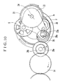
- Fig. 10 is a plan view showing the state of the film transport device at the time when the operation of thrusting out the film from the cartridge is started.
- the reduction gear 5 which is driven by the pinion gear 4 (not shown in Fig. 10) rotates in the direction of an arrow.
- the planet gear 22 is thus brought into a position where the planet gear 22 is held in a state of meshing with the internal gear part 3c of the take-up spool 3.
- the take-up spool 3 is caused by the planet gear 22 to rotate in the direction of an arrow, i.e., in the film winding direction.
- the internal gear part 3c of the take-up spool 3 has a large diameter, a sufficient amount of speed reduction is possible, despite the fact that there are only a few number of gear stages between the pinion gear 4 and the internal gear part 3c of the take-up spool 3.
- the end projection 28a of the clutch shaft 28 is restricted to be on the side of the internal gear part 3c of the take-up spool 3 by the action of the cam part 23a of the planetary plate 23.
- the planetary thrust gear 27 is kept in a state of meshing with the internal gear part 3c of the take-up spool 3. Since the planetary thrust gear 27 is rotated in such a direction that the slanting claw faces 27a of the planetary thrust gear 27 shown in Fig. 8 mesh with the slanting claw faces 26a of the planetary clutch gear 26, the planetary clutch gear 26 rotates integrally with the planetary thrust gear 27. The power of the planetary clutch gear 26 is thus transmitted to the large gear part 29a of the transmission gear 29.
- the planetary thrust gear 27 is arranged such that the power of the internal gear part 3c of the take-up spool 3 which is driven by the rotating force of the planet gear 22 is extracted from a different part of the internal gear part 3a and transmitted to the fork gear 16 by the planetary thrust gear 27.
- Fig. 11 shows in a plan view the state of the film transport device obtained immediately after the change-over from the film thrusting-out and winding-up operation to a film rewinding operation.
- the reduction gear 5 which receives power from the pinion gear 4 (not shown in Fig. 11), is driven in the direction of an arrow indicated by a broken line.
- the small gear part 22b of the planet gear 22 is then released from its state of meshing with the internal gear part 3c of the take-up spool 3 by the turning of the planetary plate 23 in the direction of an arrow indicated by a broken line, so that the planet gear 22 moves in such a direction as to mesh with the sun gear 25.
- Fig. 12 shows in a plan view the state of the film transport device where the film rewinding operation is in process.
- the small gear part 22b of the planet gear 22 is in mesh with the sun gear 25 to impart a turning force in the direction of a broken-line arrow.
- the planetary clutch gear 26, while receiving a force of revolving around the sun gear 25, is kept by the position restricting action of the cam part 23a of the planetary plate 23 in a position where the planetary thrust gear 27 never meshes with the internal gear part 3c of the take-up spool 3.
- a film rewinding driving force in the direction of a broken-line arrow is thus transmitted to the fork gear 16 through the sun gear 25, the planetary clutch gear 26, the transmission gear 29 and the idler gears 14 and 15. Therefore, the take-up spool 3 is allowed to rotate, free from the driving force of the motor, following a force of rewinding the film wound on the film winding part 3b. Then, the presence of the elastic member 33 (a leaf spring or the like) shown in Fig. 6 ensures that the film 2 can be transported without slackening its coiled state on the film winding part 3b of the take-up spool 3, even if the film winding operation and the film rewinding operation are repeatedly performed.
- the elastic member 33 a leaf spring or the like
- the spool gear disposed at the film take-up spool is used as an intermediate gear for transmission of a film transport driving force in each of the embodiments disclosed, the invention is not limited to the arrangement disclosed.
- the spool gear may be used as an intermediate gear for transmission of a driving force other than the film transport driving force, such as an optical system driving force.
- the invention may be carried out by combining as necessary the embodiments or their technological elements described in the foregoing.
- the invention is applicable to cameras of various kinds, such as a single-lens reflex camera and a lens-shutter type camera, and apparatuses other than cameras, such as a film viewing apparatus, a film using apparatus, a power transmission apparatus, etc.
Description
- The present invention relates to a film transport apparatus according to the preamble of
claim 1, for winding and rewinding a film in a camera or the like. - Among various types of photographic films, there is a type of film in which a film leader part is stowed in a cartridge until use thereof and, after the cartridge is loaded in the camera or the like, a film is thrust out from the cartridge with a spool disposed within the cartridge (hereinafter referred to as the cartridge spool) driven by a film transport mechanism disposed inside the camera or the like, as disclosed in US-A-4,832,275 and US-A-4,834,306. Such a type of film is hereinafter referred to as the thrust type.
- Further, there have been proposed various kinds of technique for winding a film thrust out from the thrust-type cartridge onto a take-up spool disposed in the camera or the like by driving the take-up spool and for rewinding the film into the cartridge by driving the cartridge spool, as disclosed in (i) JP-A-3-206435, (ii) JP-A-3-287150, (iii) JP-A-265989, etc.
- For example, in the technique disclosed in (i) JP-A-3-206435, the change-over from a film thrusting-out operation by the driving of the cartridge spool to a film winding operation by the driving of the take-up spool is smoothly performed by utilizing a one-way clutch.
- Also, in the technique disclosed in (ii) JP-A-3-287150, two transmission route channels are arranged to be selectively used to make smooth the change-over from a film thrusting-out operation by the driving of the cartridge spool to a film winding operation by the driving of the take-up spool, without using any one-way clutch.
- Further, in the technique disclosed in (iii) JP-A-6-265989, a sun gear is disposed at the last stage of a reduction gear train, and is provided with two planet gears. One of the two planet gears is arranged to be used for performing a film winding operation by the driving of the take-up spool, and the other is arranged to be used for performing a film thrusting-out operation by the driving of the cartridge spool, so that the change-over from the film thrusting-out operation to the film winding operation can be smoothly performed with a compact gear train arrangement.
- However, each of the above-mentioned kinds of technique has presented a problem in that there are required at least two channels of driving power transmission for driving the cartridge spool and for driving the take-up spool, thereby disadvantageously increasing the size of the device.
- A generic film transport apparatus is known from US-A-4 688 763 and comprises a spool which winds thereon a film taken out from a film cartridge. A motor is located in the spool. A spool gear is disposed at the spool. An output of the motor is transmitted via the spool gear to drive the spool. A film cartridge driving mechanism transmits the output of the motor to the film cartridge.
- It is an object of the present invention to further develop a film transport apparatus according to the preamble of
claim 1 such that a reduction in size and cost can be achieved. - According to the invention, this object is achieved by a film transport apparatus having the features of
claim 1. - Advantageous further developments are set out in the dependent claims.
- In accordance with the invention, the spool gear is used as an intermediate gear in transmitting the driving force, thereby enabling reduction in size and cost of the device.
- The above and other aspects and features of the invention will become apparent from the following detailed description of preferred embodiments thereof taken in conjunction with the accompanying drawings.
-
- Fig. 1 is a perspective view showing a film transport device according to a first embodiment of the invention.
- Fig. 2 is a perspective view showing a film transport device according to a second embodiment of the invention.
- Fig. 3 is a perspective view showing a film transport device according to a third embodiment of the invention.
- Fig. 4 is an exploded perspective view showing a clutch part used in each of the film transport devices in the first and third embodiments.
- Fig. 5 is an exploded perspective view showing a clutch part used in the film transport device in the second embodiment.
- Fig. 6 is a perspective view showing a film transport device according to a fourth embodiment of the invention.
- Fig. 7 is an exploded perspective view showing a gear head part as viewed from the direction of an arrow A in Fig. 6.
- Fig. 8 is an exploded perspective view showing a clutch part in the film transport device shown in Fig. 6.
- Fig. 9 is an exploded perspective view showing also the clutch part in the film transport device shown in Fig. 6.
- Fig. 10 is a plan view showing the film transport device in Fig. 6 in the state where a film thrusting-out operation is started.
- Fig. 11 is a plan view showing the film transport device in Fig. 6 in the state where the change-over to a film rewinding operation is performed.
- Fig. 12 is a plan view showing the film transport device in Fig. 6 in the state where the film rewinding operation is in process.
-
- Hereinafter, preferred embodiments of the invention will be described in detail with reference to the drawings.
- Fig. 1 shows in a perspective view a film transport device according to a first embodiment of the invention. The film transport device according to the first embodiment (also, according to other embodiments of the invention which will be described later) is used for various kinds of film using apparatuses, such as cameras, film viewers, etc.
- Referring to Fig. 1, a
film cartridge 1 is of a thrust type similar to that disclosed in U.S. Patent No. 4,832,275, U.S. Patent No. 4,834,306, etc. Specifically, as mentioned in the foregoing, the leader part of afilm 2 is stowed in thecartridge 1 until use thereof, and, after thecartridge 1 is loaded into the film transport device, thefilm 2 is thrust out from thecartridge 1 with the cartridge spool driven to rotate. - A take-
up spool 3 is arranged to wind up thereon thefilm 2 thrust out from thecartridge 1. The take-up spool 3 is provided with afilm winding part 3b the surface of which is covered with an elastic rubber material for facilitating generation of a frictional force on thefilm 2, and aspool gear 3a provided for obtaining a rotating force. Apinion gear 4 is disposed inside the take-up spool 3 and is connected directly to a motor (not shown). Afirst reduction gear 5 has alarge gear part 5a which is in mesh with thepinion gear 4. Anidler gear 6 is in mesh with asmall gear part 5b of thefirst reduction gear 5. A second reduction gear 7 has alarge gear part 7a which is in mesh with theidler gear 6 and asmall gear part 7b which is in mesh with thespool gear 3a. In a power transmission system composed of gears from thepinion gear 4 connected directly to the motor to thespool gear 3a, the gears are always in mesh with one after the other, as shown in Fig. 1, and no driving change-over member such as a planet gear or the like is included. Therefore, for example, in a case where the motor is disposed inside the take-up spool 3 as shown in Fig. 1, a reduction gear train can be closely arranged only at an upper part of a spool chamber which houses the take-up spool 3 therein. - A
planetary arm 9 is mounted on the rotating shaft of the second reduction gear 7. Aplanet gear 8 which is rotatably mounted on theplanetary arm 9 is in mesh with thelarge gear part 7a of the second reduction gear 7. Incidentally, a predetermined force of turning friction is imparted between the second reduction gear 7 and theplanetary arm 9 by a spring (not shown). - A
thrust gear 11 is arranged to be always in mesh with thespool gear 3a. Thethrust gear 11 is used as a member on the input side of aclutch part 12. A rewindinggear 13 is used as a member on the output side of theclutch part 12. - Here, an exploded perspective view of the
clutch part 12 is shown in Fig. 4. Referring to Fig. 4, acam plate 17, which is formed integrally with thethrust gear 11, is provided withprojection parts 17a formed at three positions in the peripheral part thereof. The rewindinggear 13, which is shown in a sectional view in Fig. 4, is integrally provided with a bowl-shaped clutch tube 19 which is arranged to rotatably house thecam plate 17 therein. Ashaft hole part 13a of the rewindinggear 13 and theclutch tube 19 is fitted on a rotatingshaft 11a which is formed integrally with thethrust gear 11 and thecam plate 17.Steel balls 18 are arranged between the inner wall of theclutch tube 19 and thecam plate 17. - With the
clutch part 12 configured in the above-described manner, thethrust gear 11 and the rewindinggear 13 are connected to each other when thesteel balls 18 are sandwiched in between the inner wall of theclutch tube 19 and theprojection parts 17a of thecam plate 17, and are disconnected from each other when thesteel balls 18 fall into recessed parts formed between theprojection parts 17a, depending on a relation of rotation speed between thethrust gear 11 and the rewindinggear 13. - Referring back to Fig. 1, an
idler gear 14 is in mesh with the rewindinggear 13. Anidler gear 15 is in mesh with theidler gear 14. Afork gear 16 is in mesh with theidler gear 15 and is integrally attached to afork 16a, which engages the cartridge spool to drive the cartridge spool. - Next, operation of the film transport device arranged as described above will be described. In Fig. 1, arrows shown with full lines indicate driving directions in which the members mentioned above rotate for winding (thrusting out and taking up) the
film 2. Arrows shown with broken lines indicate driving directions in which the members mentioned above rotate for rewinding thefilm 2. - First, when the
pinion gear 4 is rotated by the motor in the film winding driving direction (indicated by a full-line arrow), thegear 5 which is in mesh with thepinion gear 4, thegears 6 and 7 and thespool gear 3a respectively rotate in the directions indicated by full-line arrows. The take-upspool 3 is thus caused to rotate also in the direction of a full-line arrow. In this instance, the rotation of the second reduction gear 7 causes theplanetary arm 9 to turn in such a direction as to abut on astopper 10. As a result, theplanet gear 8 is retracted to a position where theplanet gear 8 transmits no power to any of other gears. - The
thrust gear 11, which is in mesh with thespool gear 3a, is caused to rotate in the direction of a full-line arrow by the motor driving force received through thespool gear 3. The rotation of thethrust gear 11 in the full-line arrow direction causes thesteel balls 18 to be pushed against the inner wall of theclutch tube 19 by theprojection parts 17a of thecam plate 17, so that theclutch part 12 is brought into a connecting state to cause thethrust gear 11 and therewinding gear 13 to rotate integrally. The rotation of therewinding gear 13 is transmitted to thefork gear 16 through the idler gears 14 and 15. The cartridge spool which engages thefork 16a is thus driven to rotate. As a result, thefilm 2 is thrust out from thecartridge 1. - When the
film 2 which is thrust out from thecartridge 1 reaches thefilm winding part 3b of the take-upspool 3, thefilm 2 is wound on thefilm winding part 3b without slackening under a pushing action of a pushing means (not shown). The reduction ratios of the gear trains of the film transport device are set such that a peripheral velocity of thefilm 2 on the surface of the take-upspool 3 is always faster than the speed at which thefilm 2 is being thrust out from thecartridge 1. Therefore, a portion of thefilm 2 wound on the take-upspool 3 causes thefork gear 16 to rotate at the faster speed in the direction of a full-line arrow. As a result, thefork gear 16, the idler gears 14 and 15 and therewinding gear 13 are rotated at the faster speeds in the direction of full-line arrows. When therewinding gear 13 comes to rotate at a faster speed than thethrust gear 11 in the direction of a full-line arrow, the friction between the inner wall of theclutch tube 19 and thesteel balls 18 causes thesteel balls 18 to be chased into the recessed parts formed between theprojection parts 17a of thecam plate 17. with thesteel balls 18 thus brought into the recessed part, theclutch part 12 is released from the connecting state, so that power is stopped from being transmitted from thethrust gear 11 to therewinding gear 13. Accordingly, after that, thefilm 2 comes to be wound up solely by means of the tape-upspool 3. - In addition, the
thrust gear 11 and thespool gear 3a are arranged to form a last reduction stage, excluding the reduction stage of theidler gear 15 and thefork gear 16, for the film winding driving (thegears gears fork gear 16 is driven by thefilm 2. Therefore, a load on the motor in canceling the connecting state of theclutch part 12 can be lessened. Besides, the change-over from the film thrusting-out driving to the film winding driving can be speedily and smoothly performed. - On the other hand, when the
pinion gear 4 is rotated by the motor in the direction of film rewinding (in the direction of a broken-line arrow), the reduction gears 5, 6 and 7 and thespool gear 3a respectively rotate in the directions of broken-line arrows to cause the take-upspool 3 to rotate in the direction of a broken-line arrow. Then, the rotation of the second reduction gear 7 causes theplanetary arm 9 to turn away from thestopper 10, so that theplanet gear 8 is brought to a position where theplanet gear 8 meshes with therewinding gear 13. Accordingly, the rotation of the second reduction gear 7 is transmitted to therewinding gear 13 to cause therewinding gear 13 to rotate in the direction of a broken-line arrow. - Also, the
thrust gear 11, which is in mesh with thespool gear 3a, is caused by the driving force of the motor to rotate in the direction of a broken-line arrow. Thus, therewinding gear 13 and thethrust gear 11 both receive the driving forces to be caused to rotate in the same direction across theclutch part 12. However, since the reduction ratio of a part from the motor to the rewinding gear 13 (the reduction ratio of thegears gears rewinding gear 13 always rotates slower than thethrust gear 11. Therefore, thecam plate 17 is caused to rotate in such a direction as to bring thesteel balls 18 into the recessed parts formed between theprojection parts 17a of thecam plate 17. Accordingly, at the time of film rewinding driving, theclutch part 12 is always released from the connecting state. The driving force of the motor is thus transmitted to thefork gear 16 through the second reduction gear 7, theplanet gear 8, therewinding gear 13 and the idler gears 14 and 15. - Further, in rewinding the
film 2, both thefork gear 16 and the take-upspool 3 are driven in the film rewinding direction. However, since the rewinding speed of thefilm 2 on the surface of the take-upspool 3 is set always faster than the rewinding speed of thefilm 2 on the surface of the cartridge spool which is rotated by thefork gear 16, thefilm 2 is brought into a loosely coiled state within the spool chamber, so that thefilm 2 can be prevented from being stretched. - As described above, in the film transport device according to the first embodiment, the
spool gear 3a is used not only as a gear to which the driving force of the motor for driving the take-upspool 3 is inputted, but also as an idle gear for transmitting the driving force of the motor to thethrust gear 11 which is arranged to input the driving force of the motor to a cartridge-spool driving system composed of gears from therewinding gear 13 to thefork gear 16. This arrangement permits reduction in number of gears required in the film transport device, so that efficiency of driving force transmission to the cartridge-spool driving system can be enhanced. - Further, the
spool gear 3a is disposed at the center of the spool chamber and is arranged to be relatively large in size. Therefore, the output of thespool gear 3a can be taken out from any direction. In other words, the setting position of thethrust gear 11 is selectable with a wide range of latitude. - Further, in the film transport device according to the first embodiment, the driving action for winding the film is performed by causing the
planet gear 8 to mesh with therewinding gear 13 for power transmission. Therefore, even if the location of the rewinding gear 13 (determined by the location of the thrust gear 11) is relatively far from the second reduction gear 7 (a sun gear for the planet gear 8), the distance can be easily covered by changing the size of theplanet gear 8. - The above arrangement of the film transport device according to the first embodiment thus permits the relatively thick clutch gear train (11, 12 and 13), the planet gear train (8 and 9) and the reduction gear train (5, 6 and 7) to be closely arranged above the
spool gear 3a. Thegears fork gear 16. In other words, although the film transport device includes theclutch part 12, it can be arranged without setting any bulky gear part within a thin space available above a cartridge chamber in which thefilm cartridge 1 is to be placed and also within a thin space available between the cartridge chamber and the spool chamber. Therefore, wider spaces other than these thin spaces can be used for members other than the film transport device. The arrangement described above, therefore, permits effective utilization of spaces within the apparatus using the film transport device. - In addition, since the clutch gear train (11, 12 and 13), the planet gear train (8 and 9) and the reduction gear train (5, 6 and 7) can be closely arranged above the
spool gear 3a, they can be formed into one unit. Such a unit can be also used in various kinds of apparatuses. - Further, in the first embodiment, the moving range of the
planet gear 8 is limited to two positions, i.e., the position where theplanet gear 8 is in mesh with therewinding gear 13 and the position where theplanet gear 8 is away from therewinding gear 13. Therefore, compared with a case where theplanet gear 8 is arranged, for example, to selectively mesh with two gears, theplanet gear 8 can be arranged to have a smaller moving range. Hence, the first embodiment permits reduction in size of the film transport device in this respect. - Incidentally, in the first embodiment, the
planet gear 8 may be arranged to come to mesh, for example, with theidler gear 15 instead of with therewinding gear 13 at the time of film rewinding. Such a modification can be made without difficulty as long as theclutch part 12 can be released from the connecting state for film rewinding. - Fig. 2 shows in a perspective view a film transport device according to a second embodiment of the invention. In Fig. 2, all component elements that are in common with the first embodiment shown in Fig. 1 are indicated by the same reference numerals, and the details of these elements are omitted from the following description. The second embodiment differs from the first embodiment in that the
spool gear 3a is provided with aninternal gear part 3c, thesmall gear part 7b of the second reduction gear 7 is in mesh with theinternal gear part 3c, and thethrust gear 11 is arranged to engage with thespool gear 3a (external gear part) through anidler gear 20. - In the film transport device according to the second embodiment, too, when the
pinion gear 4 is rotated by the motor in the direction of film winding (in the direction of a full-line arrow), the driving force of the motor is transmitted to thespool gear 3a through the reduction gear train (5, 6 and 7) to cause the take-upspool 3 to rotate also in the direction of a full-line arrow. In this case, the internal intermeshing of thesmall gear part 7b of the second reduction gear 7 with theinternal gear part 3c of thespool gear 3a gives a wider meshing range to make the driving action on thespool 3 more stabilized by as much as the increase in the meshing range than a case where thesmall gear part 7b is externally in mesh with thespool gear 3a as in the case of the first embodiment. - The
spool gear 3a transmits the driving force of the motor to thethrust gear 11 through theidler gear 20 to cause thethrust gear 11 to rotate in the direction of a full-line arrow. In this instance, the rotation of the second reduction gear 7 causes theplanetary arm 9 to turn in such a direction as to abut on thestopper 10, so that theplanet gear 8 is retracted to a position where theplanet gear 8 does not mesh with any gear. - As shown in Fig. 5, a clutch part 12' disposed between the
thrust gear 11 and therewinding gear 13 differs from theclutch part 12 in the first embodiment (see Fig. 4), in the shape ofprojection parts 17a' of a cam plate 17', i.e., in the biting-in direction of thesteel balls 18 into theprojection parts 17a' and theclutch tube 19. More specifically, when thethrust gear 11 rotates in the direction of a full-line arrow in Fig. 2 in thrusting out the film from the cartridge, the cam plate 17', which is formed integrally with thethrust gear 11, pushes thesteel balls 18 against the inner wall of theclutch tube 19. Therefore, the clutch part 12' comes into a connecting state to cause therewinding gear 13 to rotate at the same speed as thethrust gear 11. After that, when thefilm 2 is taken up to be wound on the take-upspool 3 and therewinding gear 13 comes to rotate in the direction of the full-line arrow at a speed faster than thethrust gear 11, the inner wall of theclutch tube 19 chases thesteel balls 18 into the recessed parts formed between theprojection parts 17a' of the cam plate 17', so that the clutch part 12' is released from the connecting state. After that, the winging driving of thefilm 2 is performed solely by means of the take-upspool 3. - On the other hand, when the
pinion gear 4 is rotated by the motor in the film rewinding direction, i.e., in the direction of a broken-line arrow, the driving force of the motor is transmitted to thespool gear 3a through the reduction gear train (5, 6 and 7) to cause the take-upspool 3 to rotate also in the direction of a broken-line arrow. Further, thespool gear 3a transmits the driving force of the motor also to thethrust gear 11 through theidler gear 20 to cause thethrust gear 11 to rotate in the direction of a broken-line arrow. In this instance, the rotation of the second reduction gear 7 causes theplanetary arm 9 to turn away from thestopper 10. As a result, theplanet gear 8 comes to mesh with therewinding gear 13 to cause therewinding gear 13 to rotate in the direction of a broken-line arrow. - Both the
rewinding gear 13 and thethrust gear 11 thus rotate in the same direction with the clutch part 12' interposed between them. However, the reduction ratio of a part from the motor to the rewinding gear 13 (the reduction ratio of thegears gears rewinding gear 13 rotates always slower than thethrust gear 11. Hence, the cam plate 17' then rotates in such a direction as to chase thesteel balls 18 into the recessed parts formed between theprojection parts 17a', thereby releasing the clutch part 12' from the connecting state at the time of driving for film rewinding. In this instance, therefore, the driving force of the motor is transmitted to thefork gear 16 through the second reduction gear 7, theplanet gear 8, therewinding gear 13 and theidler gear 14. - With the film transport device according to the second embodiment arranged in the above-described manner, the same advantageous effect as that of the first embodiment can be attained.
- Fig. 3 shows in a perspective view a film transport device according to a third embodiment of the invention. All the component elements of the third embodiment that are in common with those of the second embodiment are indicated by the same reference numerals, and the details of them are omitted from the following description. The third embodiment differs from the second embodiment in that the
spool gear 3a and thethrust gear 11 are arranged to intermesh directly with each other, and anidler gear 21 is interposed in between theplanet gear 8 and therewinding gear 13 which are arranged to engage with each other in driving for film rewinding. - In the film transport device according to the third embodiment, too, when the
pinion gear 4 is rotated by the motor in the direction of film winding, i.e., in the direction of a full-line arrow as shown in Fig. 3, the driving force of the motor is transmitted to thespool gear 3a through the reduction gear train (5, 6 and 7). The take-upspool 3 then also rotates in the direction of a full-line arrow. - Further, the
spool gear 3a transmits the driving force of the motor also to thethrust gear 11 to cause thethrust gear 11 to rotate in the direction of a full-line arrow. In this instance, the rotation of the second reduction gear 7 causes theplanetary arm 9 to turn in such a direction as to abut on thestopper 10. As a result, theplanet gear 8 is retracted to a position where theplanet gear 8 does not mesh with any gear. - The
clutch part 12 disposed between thethrust gear 11 and therewinding gear 13 is the same as the clutch part in the first embodiment (see Fig. 4). When thethrust gear 11 rotates in the direction of a full-line arrow in Fig. 3 in thrusting out the film from the cartridge, thecam plate 17, which is formed integrally with thethrust gear 11, pushes the steel balls against the inner wall of theclutch tube 19, so that theclutch part 12 is brought into a connecting state. Therewinding gear 13 thus rotates at the same speed as thethrust gear 11. After that, when thefilm 2 is taken up to be wound on the take-upspool 3 and therewinding gear 13 comes to rotate in the direction of the full-line arrow at a speed faster than thethrust gear 11, the inner wall of theclutch tube 19 chases thesteel balls 18 into the recessed parts formed between theprojection parts 17a of thecam plate 17, so that theclutch part 12 is released from the connecting state. After that, the winging driving of thefilm 2 is performed solely by means of the take-upspool 3. - On the other hand, when the
pinion gear 4 is rotated by the motor in the film rewinding direction, i.e., in the direction of a broken-line arrow, the driving force of the motor is transmitted to thespool gear 3a through the reduction gear train (5, 6 and 7) to cause the take-upspool 3 to rotate also in the direction of a broken-line arrow. Further, thespool gear 3a transmits the driving force of the motor also to thethrust gear 11 to cause thethrust gear 11 to rotate in the direction of a broken-line arrow. In this instance, the rotation of the second reduction gear 7 causes theplanetary arm 9 to turn away from thestopper 10. As a result, theplanet gear 8 comes to engage with therewinding gear 13 through theidler gear 21 to cause therewinding gear 13 to rotate in the direction of a broken-line arrow. - Both the
rewinding gear 13 and thethrust gear 11 thus rotate in the same direction with theclutch part 12 interposed between them. However, the reduction ratio of a part from the motor to the rewinding gear 13 (the reduction ratio of thegears gears rewinding gear 13 rotates always slower than thethrust gear 11. Hence, thecam plate 17 then rotates in such a direction as to chase thesteel balls 18 into the recessed parts formed between theprojection parts 17a, thereby releasing theclutch part 12 from the connecting state at the time of driving for film rewinding. In this instance, therefore, the driving force of the motor is transmitted to thefork gear 16 through the second reduction gear 7, theplanet gear 8, therewinding gear 13 and the idler gears 14 and 15. - With the film transport device according to the third embodiment arranged in the above-described manner, the same advantageous effect can be attained as in the cases of the first and second embodiments.
- Fig. 6 shows in a perspective view a film transport device according to a fourth embodiment of the invention. Fig. 7 is an exploded perspective view showing a gear head part of the film transport device as viewed from the direction of an arrow A in Fig. 6. In Figs. 6 and 7, all component elements that are in common with the above-described embodiments are indicated by the same reference numerals, and the details of them are omitted from the following description.
- Referring to Figs. 6 and 7, a
pinion gear 4 is connected directly to a film transport motor (not shown). Areduction gear 5 has alarge gear part 5a which is in mesh with thepinion gear 4. Aplanet gear 22 is arranged to have thereduction gear 5 as a sun gear and to revolve around thereduction gear 5. Alarge gear part 22a of theplanet gear 22 is in mesh with asmall gear part 5b of thereduction gear 5. Aplanetary plate 23 is arranged to cause asmall gear part 22b of theplanet gear 22 to be selectively come to mesh with theinternal gear part 3c of the take-upspool 3 or with asun gear 25. Aplanet shaft 24 is arranged to rotatably carry theplanet gear 22 through a spring (not shown). Thesun gear 25 is arranged to rotate in a fixed position where thesun gear 25 never meshes with theinternal gear part 3c of the take-upspool 3. A planetaryclutch gear 26 is arranged to be always in mesh with thesun gear 25 and alarge gear part 29a of atransmission gear 29 and to turn around thesun gear 25. Aplanetary thrust gear 27 is arranged to turn around thesun gear 25 between a position where theplanetary thrust gear 27 meshes with theinternal gear part 3c of the take-upspool 3 and another position where theplanetary thrust gear 27 does not mesh with theinternal gear part 3c, while carrying out a clutching function between theplanetary thrust gear 27 and the planetaryclutch gear 26. Aclutch shaft 28 acts as a rotating shaft for the planetaryclutch gear 26 and theplanetary thrust gear 27. Theclutch shaft 28 has anend projection 28a which engages acam part 23a of theplanetary plate 23, so that the position of theclutch shaft 28, i.e., the revolving position of theplanetary thrust gear 27, is controlled by theplanetary plate 23. - Figs. 8 and 9 are exploded perspective views showing a clutch part composed of the planetary
clutch gear 26 and theplanetary thrust gear 27 shown in Fig. 6. Referring to Figs. 8 and 9, a sun-gear rotation sleeve 31 is caulked integrally with theplanetary plate 30 and is fitted in thesun gear 25. The planetaryclutch gear 26 is provided with slanting claw faces 26a on its lower side as shown in Fig. 9. Theplanetary thrust gear 27 is also provided with slanting claw faces 27a as shown in Fig. 8. Theclutch shaft 28 is carried by theplanetary plate 30 while compressing acoil spring 32 to push the planetaryclutch gear 26 against theplanetary thrust gear 27. - Next, operation of the film transport device arranged as described above according to the fourth embodiment will be described. Fig. 10 is a plan view showing the state of the film transport device at the time when the operation of thrusting out the film from the cartridge is started. Referring to Fig. 10, the
reduction gear 5 which is driven by the pinion gear 4 (not shown in Fig. 10) rotates in the direction of an arrow. Theplanet gear 22, which is in mesh with thereduction gear 5, receives a revolving force which is exerted on theplanet shaft 24 in the direction of an arrow. Theplanet gear 22 is thus brought into a position where theplanet gear 22 is held in a state of meshing with theinternal gear part 3c of the take-upspool 3. In this position, theplanet gear 22 is out of mesh with thesun gear 25. Then, the take-upspool 3 is caused by theplanet gear 22 to rotate in the direction of an arrow, i.e., in the film winding direction. In this instance, since theinternal gear part 3c of the take-upspool 3 has a large diameter, a sufficient amount of speed reduction is possible, despite the fact that there are only a few number of gear stages between thepinion gear 4 and theinternal gear part 3c of the take-upspool 3. - Further, the
end projection 28a of theclutch shaft 28 is restricted to be on the side of theinternal gear part 3c of the take-upspool 3 by the action of thecam part 23a of theplanetary plate 23. By virtue of this action, theplanetary thrust gear 27 is kept in a state of meshing with theinternal gear part 3c of the take-upspool 3. Since theplanetary thrust gear 27 is rotated in such a direction that the slanting claw faces 27a of theplanetary thrust gear 27 shown in Fig. 8 mesh with the slanting claw faces 26a of the planetaryclutch gear 26, the planetaryclutch gear 26 rotates integrally with theplanetary thrust gear 27. The power of the planetaryclutch gear 26 is thus transmitted to thelarge gear part 29a of thetransmission gear 29. In other words, theplanetary thrust gear 27 is arranged such that the power of theinternal gear part 3c of the take-upspool 3 which is driven by the rotating force of theplanet gear 22 is extracted from a different part of theinternal gear part 3a and transmitted to thefork gear 16 by theplanetary thrust gear 27. - In the state shown in Fig. 6, the individual gears rotate in the direction of full-line arrows, and the
film 2 is driven by thefork gear 16 to be thrust out from thecartridge 1. Thefilm 2 which is thrust out is taken up to be wound on the take-up spool in a state of being pushed by anelastic member 33 against the take-upspool 3. Then, since the film winding speed of the take-upspool 3 is set faster than the film thrusting-out speed of thefork gear 16, thefilm 2 is pulled out from thecartridge 1 at a speed faster than the film thrusting-out speed of thefork gear 16. Therefore, a tensile force of thetape 2 caused by the rotation of the take-upspool 3 is transmitted to thefork gear 16. Then, since the planetaryclutch gear 26 is caused to rotate in the direction of a full-line arrow at a speed faster than theplanetary thrust gear 27, the engaging connection between the planetaryclutch gear 26 and theplanetary thrust gear 27 is canceled, so that thefilm 2 is wound up solely by the rotation of the take-upspool 3. Incidentally, in this instance, since thesun gear 25 is always in mesh with the planetaryclutch gear 26, thesun gear 25 is driven to rotate by the planetaryclutch gear 26. However, the rotation of thesun gear 25 is nothing but an idle rotation. Therefore, thefilm 2 can be thrust out and wound up without hindrance. - Fig. 11 shows in a plan view the state of the film transport device obtained immediately after the change-over from the film thrusting-out and winding-up operation to a film rewinding operation. Referring to Fig. 11, the
reduction gear 5, which receives power from the pinion gear 4 (not shown in Fig. 11), is driven in the direction of an arrow indicated by a broken line. Thesmall gear part 22b of theplanet gear 22 is then released from its state of meshing with theinternal gear part 3c of the take-upspool 3 by the turning of theplanetary plate 23 in the direction of an arrow indicated by a broken line, so that theplanet gear 22 moves in such a direction as to mesh with thesun gear 25. At the same time, theend projection 28a of theclutch shaft 28 is caused by the motion of thecam part 23a of theplanetary plate 23 to move in the direction of a broken-line arrow to a position where theplanetary thrust gear 27 never meshes with theinternal gear part 3c of the take-upspool 3. - Fig. 12 shows in a plan view the state of the film transport device where the film rewinding operation is in process. In this state, the
small gear part 22b of theplanet gear 22 is in mesh with thesun gear 25 to impart a turning force in the direction of a broken-line arrow. The planetaryclutch gear 26, while receiving a force of revolving around thesun gear 25, is kept by the position restricting action of thecam part 23a of theplanetary plate 23 in a position where theplanetary thrust gear 27 never meshes with theinternal gear part 3c of the take-upspool 3. A film rewinding driving force in the direction of a broken-line arrow is thus transmitted to thefork gear 16 through thesun gear 25, the planetaryclutch gear 26, thetransmission gear 29 and the idler gears 14 and 15. Therefore, the take-upspool 3 is allowed to rotate, free from the driving force of the motor, following a force of rewinding the film wound on thefilm winding part 3b. Then, the presence of the elastic member 33 (a leaf spring or the like) shown in Fig. 6 ensures that thefilm 2 can be transported without slackening its coiled state on thefilm winding part 3b of the take-upspool 3, even if the film winding operation and the film rewinding operation are repeatedly performed. - With the film transport device according to the fourth embodiment arranged as described above, the same advantageous effect can be attained as in the cases of the above-described embodiments.
- The individual components shown in schematic or block form in the drawings are all well-known in the camera arts and their specific construction and operation are not critical to the operation or best mode for carrying out the invention.
- While the invention has been described with respect to what is presently considered to be the preferred embodiments, it is to be understood that the invention is not limited to the disclosed embodiments. To the contrary, the invention is intended to cover various modifications and equivalent arrangements included within the scope of the appended claims.
- For example, while the spool gear disposed at the film take-up spool is used as an intermediate gear for transmission of a film transport driving force in each of the embodiments disclosed, the invention is not limited to the arrangement disclosed. The spool gear may be used as an intermediate gear for transmission of a driving force other than the film transport driving force, such as an optical system driving force.
- The invention may be carried out by combining as necessary the embodiments or their technological elements described in the foregoing.
- Further, the invention is applicable to cameras of various kinds, such as a single-lens reflex camera and a lens-shutter type camera, and apparatuses other than cameras, such as a film viewing apparatus, a film using apparatus, a power transmission apparatus, etc.
Claims (5)
- A film transport apparatus comprising a spool (3) which winds thereon a film (2) taken out from a film cartridge (1), a motor located in the spool (3), a spool gear (3a) disposed at the spool (3) and to which an output of the motor is transmitted to drive the spool (3), and a film cartridge driving mechanism (4, 5, 6, 7, 8, 11, 12, 13, 14, 15, 16) which transmits the output of the motor to the film cartridge (1),
characterized in that
when the film (2) is fed out, the film cartridge driving mechanism (4, 5, 6, 7, 8, 11, 12, 14, 14, 15, 16) transmits the output of the motor to the film cartridge (1) through the spool gear (3a), and when the film is rewound, the film cartridge driving mechanism changes the transmission route of the output of the motor so as to transmit the output to the film cartridge (1) without passing through the spool gear (3a). - A film transport apparatus according to claim 1, wherein the spool gear (3a) is formed on the outer periphery of the spool (3).
- A film transport apparatus according to claim 1, wherein the spool gear (3a) is formed on the inner periphery of the spool (3).
- A film transport apparatus according to claim 1, wherein the film cartridge driving mechanism has a planetary clutch mechanism (7, 8) having a sun gear (7) which engages with the spool gear (3a).
- A film transport apparatus according to claim 1, wherein the film cartridge driving mechanism has a clutch (12) which cuts off the connection between two gears (11, 13) of the mechanism when the gears are different in their speeds.
Applications Claiming Priority (3)
| Application Number | Priority Date | Filing Date | Title |
|---|---|---|---|
| JP35152996 | 1996-12-27 | ||
| JP351529/96 | 1996-12-27 | ||
| JP35152996 | 1996-12-27 |
Publications (3)
| Publication Number | Publication Date |
|---|---|
| EP0851273A2 EP0851273A2 (en) | 1998-07-01 |
| EP0851273A3 EP0851273A3 (en) | 2000-01-19 |
| EP0851273B1 true EP0851273B1 (en) | 2004-12-08 |
Family
ID=18417913
Family Applications (1)
| Application Number | Title | Priority Date | Filing Date |
|---|---|---|---|
| EP97122911A Expired - Lifetime EP0851273B1 (en) | 1996-12-27 | 1997-12-24 | Film transport apparatus |
Country Status (6)
| Country | Link |
|---|---|
| US (1) | US6170999B1 (en) |
| EP (1) | EP0851273B1 (en) |
| KR (1) | KR100261390B1 (en) |
| CN (1) | CN1149441C (en) |
| DE (1) | DE69731876T2 (en) |
| TW (1) | TW367426B (en) |
Families Citing this family (7)
| Publication number | Priority date | Publication date | Assignee | Title |
|---|---|---|---|---|
| JP2000081658A (en) * | 1998-09-03 | 2000-03-21 | Canon Inc | Film feeding device and optical equipment provided with the device |
| JP2001099243A (en) * | 1999-09-29 | 2001-04-10 | Canon Inc | Power transmission device, film feeding device, and optical apparatus |
| KR100335500B1 (en) * | 2000-05-16 | 2002-05-08 | 윤종용 | Method for controlling cache system which comprises direct-mapped cache and fully-associative buffer |
| JP5220284B2 (en) * | 2006-05-15 | 2013-06-26 | 株式会社ハーモニック・ドライブ・システムズ | Film winding roll rotation mechanism |
| EP2737364B1 (en) * | 2011-07-29 | 2018-04-18 | Robert Bosch GmbH | Linear actuator and camera with a motorized back focus module with the linear actuator |
| CN107477171A (en) * | 2017-08-01 | 2017-12-15 | 梁文元 | A kind of gear drive folding structure |
| CN108761782A (en) * | 2018-06-20 | 2018-11-06 | 东莞市维斗科技股份有限公司 | A kind of monitoring camera dust-proof mechanism |
Family Cites Families (13)
| Publication number | Priority date | Publication date | Assignee | Title |
|---|---|---|---|---|
| JPS56132324A (en) * | 1980-03-22 | 1981-10-16 | Canon Inc | Film feeder for camera |
| US4688763A (en) | 1983-10-01 | 1987-08-25 | Nippon Kogaku K. K. | Film feeding device in a camera |
| US4832275A (en) | 1988-05-19 | 1989-05-23 | Eastman Kodak Company | Film cassette |
| JP2706489B2 (en) | 1988-10-17 | 1998-01-28 | ウエスト電気 株式会社 | Electric film feeder |
| JP2890641B2 (en) | 1989-10-26 | 1999-05-17 | 株式会社ニコン | Hoisting / rewinding device |
| JPH03287150A (en) * | 1990-04-02 | 1991-12-17 | Nikon Corp | Film feeding device for camera |
| JP3110507B2 (en) * | 1991-09-19 | 2000-11-20 | ウエスト電気株式会社 | Film electric hoist |
| JP3208882B2 (en) * | 1993-01-05 | 2001-09-17 | ミノルタ株式会社 | Camera and operating mechanism |
| JPH07110518A (en) * | 1993-10-14 | 1995-04-25 | Fuji Photo Optical Co Ltd | Camera |
| JPH07175114A (en) * | 1993-12-17 | 1995-07-14 | Olympus Optical Co Ltd | Film feeder for camera |
| JPH0829841A (en) * | 1994-07-15 | 1996-02-02 | Fuji Photo Optical Co Ltd | Film feeder |
| JPH08160511A (en) * | 1994-12-02 | 1996-06-21 | Nikon Corp | Film feeding device |
| US5555048A (en) * | 1995-01-20 | 1996-09-10 | Eastman Kodak Company | Dual floating gear system for a film transport mechanism |
-
1997
- 1997-12-19 US US08/994,425 patent/US6170999B1/en not_active Expired - Fee Related
- 1997-12-23 TW TW086119603A patent/TW367426B/en not_active IP Right Cessation
- 1997-12-24 EP EP97122911A patent/EP0851273B1/en not_active Expired - Lifetime
- 1997-12-24 DE DE69731876T patent/DE69731876T2/en not_active Expired - Lifetime
- 1997-12-26 CN CNB971232865A patent/CN1149441C/en not_active Expired - Fee Related
- 1997-12-27 KR KR1019970074863A patent/KR100261390B1/en not_active IP Right Cessation
Also Published As
| Publication number | Publication date |
|---|---|
| CN1149441C (en) | 2004-05-12 |
| KR19980064730A (en) | 1998-10-07 |
| US6170999B1 (en) | 2001-01-09 |
| CN1190749A (en) | 1998-08-19 |
| DE69731876D1 (en) | 2005-01-13 |
| TW367426B (en) | 1999-08-21 |
| KR100261390B1 (en) | 2000-07-01 |
| DE69731876T2 (en) | 2005-11-24 |
| EP0851273A2 (en) | 1998-07-01 |
| EP0851273A3 (en) | 2000-01-19 |
Similar Documents
| Publication | Publication Date | Title |
|---|---|---|
| US5456419A (en) | Film feeder for cameras | |
| EP0851273B1 (en) | Film transport apparatus | |
| US5640637A (en) | Apparatus and method for moving film | |
| JPS6242489B2 (en) | ||
| JPH0267535A (en) | Film feeder for camera | |
| US6336751B1 (en) | Film feeding device, and optical apparatus including the same | |
| US6361224B1 (en) | Film transport device and camera | |
| US5576784A (en) | Film transport device of camera | |
| JPH0267534A (en) | Film feeder for camera | |
| US5138352A (en) | Camera | |
| JPH09236854A (en) | Drive switching machanism for camera | |
| KR0184952B1 (en) | Film winding/rewinding mechanism of advanced photo photo system | |
| JPH09281569A (en) | Camera | |
| US6276845B1 (en) | Power transmission mechanism | |
| US6418816B1 (en) | Power transmission device | |
| JP3431345B2 (en) | camera | |
| JP2633350B2 (en) | Switching clutch mechanism and film electric feeder using this mechanism | |
| JPH10239743A (en) | Motive power transmitting device for camera, and device using the same | |
| JP3853870B2 (en) | Driving force transmission mechanism | |
| JPH0733221Y2 (en) | Camera screen spacing retention mechanism | |
| US6125241A (en) | Camera | |
| JP2001066679A (en) | Film feeder, and optical equipment provided with the same | |
| JPH0289038A (en) | Auto loading device for film in camera | |
| JPH10268394A (en) | Film feeding mechanism for camera | |
| JPH09230452A (en) | Film feeding mechanism for camera |
Legal Events
| Date | Code | Title | Description |
|---|---|---|---|
| PUAI | Public reference made under article 153(3) epc to a published international application that has entered the european phase |
Free format text: ORIGINAL CODE: 0009012 |
|
| AK | Designated contracting states |
Kind code of ref document: A2 Designated state(s): DE FR GB |
|
| AX | Request for extension of the european patent |
Free format text: AL;LT;LV;MK;RO;SI |
|
| PUAL | Search report despatched |
Free format text: ORIGINAL CODE: 0009013 |
|
| AK | Designated contracting states |
Kind code of ref document: A3 Designated state(s): AT BE CH DE DK ES FI FR GB GR IE IT LI LU MC NL PT SE |
|
| AX | Request for extension of the european patent |
Free format text: AL;LT;LV;MK;RO;SI |
|
| 17P | Request for examination filed |
Effective date: 20000531 |
|
| AKX | Designation fees paid |
Free format text: DE FR GB |
|
| 17Q | First examination report despatched |
Effective date: 20030821 |
|
| GRAP | Despatch of communication of intention to grant a patent |
Free format text: ORIGINAL CODE: EPIDOSNIGR1 |
|
| RTI1 | Title (correction) |
Free format text: FILM TRANSPORT APPARATUS |
|
| GRAS | Grant fee paid |
Free format text: ORIGINAL CODE: EPIDOSNIGR3 |
|
| GRAA | (expected) grant |
Free format text: ORIGINAL CODE: 0009210 |
|
| AK | Designated contracting states |
Kind code of ref document: B1 Designated state(s): DE FR GB |
|
| REG | Reference to a national code |
Ref country code: GB Ref legal event code: FG4D |
|
| REF | Corresponds to: |
Ref document number: 69731876 Country of ref document: DE Date of ref document: 20050113 Kind code of ref document: P |
|
| ET | Fr: translation filed | ||
| PLBE | No opposition filed within time limit |
Free format text: ORIGINAL CODE: 0009261 |
|
| STAA | Information on the status of an ep patent application or granted ep patent |
Free format text: STATUS: NO OPPOSITION FILED WITHIN TIME LIMIT |
|
| 26N | No opposition filed |
Effective date: 20050909 |
|
| PGFP | Annual fee paid to national office [announced via postgrant information from national office to epo] |
Ref country code: GB Payment date: 20101223 Year of fee payment: 14 |
|
| PGFP | Annual fee paid to national office [announced via postgrant information from national office to epo] |
Ref country code: DE Payment date: 20101231 Year of fee payment: 14 |
|
| PGFP | Annual fee paid to national office [announced via postgrant information from national office to epo] |
Ref country code: FR Payment date: 20120103 Year of fee payment: 15 |
|
| GBPC | Gb: european patent ceased through non-payment of renewal fee |
Effective date: 20121224 |
|
| REG | Reference to a national code |
Ref country code: FR Ref legal event code: ST Effective date: 20130830 |
|
| PG25 | Lapsed in a contracting state [announced via postgrant information from national office to epo] |
Ref country code: DE Free format text: LAPSE BECAUSE OF NON-PAYMENT OF DUE FEES Effective date: 20130702 |
|
| REG | Reference to a national code |
Ref country code: DE Ref legal event code: R119 Ref document number: 69731876 Country of ref document: DE Effective date: 20130702 |
|
| PG25 | Lapsed in a contracting state [announced via postgrant information from national office to epo] |
Ref country code: FR Free format text: LAPSE BECAUSE OF NON-PAYMENT OF DUE FEES Effective date: 20130102 Ref country code: GB Free format text: LAPSE BECAUSE OF NON-PAYMENT OF DUE FEES Effective date: 20121224 |