EP0850687A2 - Device for solid particles treatment in a fluidized bed and use therof - Google Patents
Device for solid particles treatment in a fluidized bed and use therof Download PDFInfo
- Publication number
- EP0850687A2 EP0850687A2 EP97403156A EP97403156A EP0850687A2 EP 0850687 A2 EP0850687 A2 EP 0850687A2 EP 97403156 A EP97403156 A EP 97403156A EP 97403156 A EP97403156 A EP 97403156A EP 0850687 A2 EP0850687 A2 EP 0850687A2
- Authority
- EP
- European Patent Office
- Prior art keywords
- particles
- treatment
- fluidized bed
- enclosure
- fluid
- Prior art date
- Legal status (The legal status is an assumption and is not a legal conclusion. Google has not performed a legal analysis and makes no representation as to the accuracy of the status listed.)
- Ceased
Links
Images


Classifications
-
- C—CHEMISTRY; METALLURGY
- C10—PETROLEUM, GAS OR COKE INDUSTRIES; TECHNICAL GASES CONTAINING CARBON MONOXIDE; FUELS; LUBRICANTS; PEAT
- C10G—CRACKING HYDROCARBON OILS; PRODUCTION OF LIQUID HYDROCARBON MIXTURES, e.g. BY DESTRUCTIVE HYDROGENATION, OLIGOMERISATION, POLYMERISATION; RECOVERY OF HYDROCARBON OILS FROM OIL-SHALE, OIL-SAND, OR GASES; REFINING MIXTURES MAINLY CONSISTING OF HYDROCARBONS; REFORMING OF NAPHTHA; MINERAL WAXES
- C10G11/00—Catalytic cracking, in the absence of hydrogen, of hydrocarbon oils
- C10G11/14—Catalytic cracking, in the absence of hydrogen, of hydrocarbon oils with preheated moving solid catalysts
- C10G11/18—Catalytic cracking, in the absence of hydrogen, of hydrocarbon oils with preheated moving solid catalysts according to the "fluidised-bed" technique
-
- B—PERFORMING OPERATIONS; TRANSPORTING
- B01—PHYSICAL OR CHEMICAL PROCESSES OR APPARATUS IN GENERAL
- B01J—CHEMICAL OR PHYSICAL PROCESSES, e.g. CATALYSIS OR COLLOID CHEMISTRY; THEIR RELEVANT APPARATUS
- B01J19/00—Chemical, physical or physico-chemical processes in general; Their relevant apparatus
- B01J19/32—Packing elements in the form of grids or built-up elements for forming a unit or module inside the apparatus for mass or heat transfer
-
- B—PERFORMING OPERATIONS; TRANSPORTING
- B01—PHYSICAL OR CHEMICAL PROCESSES OR APPARATUS IN GENERAL
- B01J—CHEMICAL OR PHYSICAL PROCESSES, e.g. CATALYSIS OR COLLOID CHEMISTRY; THEIR RELEVANT APPARATUS
- B01J8/00—Chemical or physical processes in general, conducted in the presence of fluids and solid particles; Apparatus for such processes
- B01J8/08—Chemical or physical processes in general, conducted in the presence of fluids and solid particles; Apparatus for such processes with moving particles
- B01J8/12—Chemical or physical processes in general, conducted in the presence of fluids and solid particles; Apparatus for such processes with moving particles moved by gravity in a downward flow
-
- B—PERFORMING OPERATIONS; TRANSPORTING
- B01—PHYSICAL OR CHEMICAL PROCESSES OR APPARATUS IN GENERAL
- B01J—CHEMICAL OR PHYSICAL PROCESSES, e.g. CATALYSIS OR COLLOID CHEMISTRY; THEIR RELEVANT APPARATUS
- B01J8/00—Chemical or physical processes in general, conducted in the presence of fluids and solid particles; Apparatus for such processes
- B01J8/18—Chemical or physical processes in general, conducted in the presence of fluids and solid particles; Apparatus for such processes with fluidised particles
- B01J8/24—Chemical or physical processes in general, conducted in the presence of fluids and solid particles; Apparatus for such processes with fluidised particles according to "fluidised-bed" technique
- B01J8/34—Chemical or physical processes in general, conducted in the presence of fluids and solid particles; Apparatus for such processes with fluidised particles according to "fluidised-bed" technique with stationary packing material in the fluidised bed, e.g. bricks, wire rings, baffles
-
- C—CHEMISTRY; METALLURGY
- C10—PETROLEUM, GAS OR COKE INDUSTRIES; TECHNICAL GASES CONTAINING CARBON MONOXIDE; FUELS; LUBRICANTS; PEAT
- C10G—CRACKING HYDROCARBON OILS; PRODUCTION OF LIQUID HYDROCARBON MIXTURES, e.g. BY DESTRUCTIVE HYDROGENATION, OLIGOMERISATION, POLYMERISATION; RECOVERY OF HYDROCARBON OILS FROM OIL-SHALE, OIL-SAND, OR GASES; REFINING MIXTURES MAINLY CONSISTING OF HYDROCARBONS; REFORMING OF NAPHTHA; MINERAL WAXES
- C10G11/00—Catalytic cracking, in the absence of hydrogen, of hydrocarbon oils
- C10G11/14—Catalytic cracking, in the absence of hydrogen, of hydrocarbon oils with preheated moving solid catalysts
- C10G11/18—Catalytic cracking, in the absence of hydrogen, of hydrocarbon oils with preheated moving solid catalysts according to the "fluidised-bed" technique
- C10G11/182—Regeneration
-
- B—PERFORMING OPERATIONS; TRANSPORTING
- B01—PHYSICAL OR CHEMICAL PROCESSES OR APPARATUS IN GENERAL
- B01J—CHEMICAL OR PHYSICAL PROCESSES, e.g. CATALYSIS OR COLLOID CHEMISTRY; THEIR RELEVANT APPARATUS
- B01J2208/00—Processes carried out in the presence of solid particles; Reactors therefor
- B01J2208/00796—Details of the reactor or of the particulate material
- B01J2208/00823—Mixing elements
- B01J2208/00831—Stationary elements
- B01J2208/0084—Stationary elements inside the bed, e.g. baffles
-
- B—PERFORMING OPERATIONS; TRANSPORTING
- B01—PHYSICAL OR CHEMICAL PROCESSES OR APPARATUS IN GENERAL
- B01J—CHEMICAL OR PHYSICAL PROCESSES, e.g. CATALYSIS OR COLLOID CHEMISTRY; THEIR RELEVANT APPARATUS
- B01J2219/00—Chemical, physical or physico-chemical processes in general; Their relevant apparatus
- B01J2219/32—Details relating to packing elements in the form of grids or built-up elements for forming a unit of module inside the apparatus for mass or heat transfer
- B01J2219/322—Basic shape of the elements
- B01J2219/32203—Sheets
- B01J2219/32206—Flat sheets
-
- B—PERFORMING OPERATIONS; TRANSPORTING
- B01—PHYSICAL OR CHEMICAL PROCESSES OR APPARATUS IN GENERAL
- B01J—CHEMICAL OR PHYSICAL PROCESSES, e.g. CATALYSIS OR COLLOID CHEMISTRY; THEIR RELEVANT APPARATUS
- B01J2219/00—Chemical, physical or physico-chemical processes in general; Their relevant apparatus
- B01J2219/32—Details relating to packing elements in the form of grids or built-up elements for forming a unit of module inside the apparatus for mass or heat transfer
- B01J2219/322—Basic shape of the elements
- B01J2219/32203—Sheets
- B01J2219/3221—Corrugated sheets
-
- B—PERFORMING OPERATIONS; TRANSPORTING
- B01—PHYSICAL OR CHEMICAL PROCESSES OR APPARATUS IN GENERAL
- B01J—CHEMICAL OR PHYSICAL PROCESSES, e.g. CATALYSIS OR COLLOID CHEMISTRY; THEIR RELEVANT APPARATUS
- B01J2219/00—Chemical, physical or physico-chemical processes in general; Their relevant apparatus
- B01J2219/32—Details relating to packing elements in the form of grids or built-up elements for forming a unit of module inside the apparatus for mass or heat transfer
- B01J2219/322—Basic shape of the elements
- B01J2219/32203—Sheets
- B01J2219/32213—Plurality of essentially parallel sheets
-
- B—PERFORMING OPERATIONS; TRANSPORTING
- B01—PHYSICAL OR CHEMICAL PROCESSES OR APPARATUS IN GENERAL
- B01J—CHEMICAL OR PHYSICAL PROCESSES, e.g. CATALYSIS OR COLLOID CHEMISTRY; THEIR RELEVANT APPARATUS
- B01J2219/00—Chemical, physical or physico-chemical processes in general; Their relevant apparatus
- B01J2219/32—Details relating to packing elements in the form of grids or built-up elements for forming a unit of module inside the apparatus for mass or heat transfer
- B01J2219/322—Basic shape of the elements
- B01J2219/32203—Sheets
- B01J2219/32224—Sheets characterised by the orientation of the sheet
- B01J2219/32227—Vertical orientation
-
- B—PERFORMING OPERATIONS; TRANSPORTING
- B01—PHYSICAL OR CHEMICAL PROCESSES OR APPARATUS IN GENERAL
- B01J—CHEMICAL OR PHYSICAL PROCESSES, e.g. CATALYSIS OR COLLOID CHEMISTRY; THEIR RELEVANT APPARATUS
- B01J2219/00—Chemical, physical or physico-chemical processes in general; Their relevant apparatus
- B01J2219/32—Details relating to packing elements in the form of grids or built-up elements for forming a unit of module inside the apparatus for mass or heat transfer
- B01J2219/324—Composition or microstructure of the elements
- B01J2219/32466—Composition or microstructure of the elements comprising catalytically active material
Definitions
- the present invention relates to the operations of treatment of cracked catalyst particles catalytic in the fluid state, and more particularly the stripping and regeneration of the catalyst. More specifically, it relates to a device and a process for treating, with a fluid circulating against the current, the particles of catalyst in a dense fluidized bed, in particular to eliminate the pollutants entrained with these particles and / or adsorbed thereon.
- Catalyst particles are rapidly deactivated during the short time they are in contact with the charge, mainly due to adsorption of hydrocarbons, as well as a deposit of coke and other contaminants on their active sites . It is therefore necessary to continuously stripped the deactivated grains of catalyst, to recover the adsorbed hydrocarbons and entrained in the empty volumes separating these grains, then to regenerate these grains of catalyst, also continuously, by controlled combustion of coke, in a regeneration section with one or more stages. The catalyst grains are then recycled to the reaction zone.
- These two treatment operations namely stripping and regeneration, are carried out in a dense fluidized bed, that is to say with a density of between 400 and 800 kg / m 3 .
- stripping is carried out in an enclosure located at the outlet of the column reaction, whether ascending or descending, after separation of effluents from the reaction zone.
- stripping operates in dense fluidized phase.
- a gaseous fluid of preferably very polar (water vapor for example), is injected at the base of the enclosure and backwashing the suspension of deactivated grains of catalyst. It allows the displacement and recovery of hydrocarbons, which are either entrained in the empty spaces left between the grains of deactivated catalysts, or adsorbed to their area.
- the stripped catalyst grains are evacuated by an outlet located at the base of the enclosure.
- the residence time of the catalyst particles in the stripper must be as homogeneous as possible. Indeed, if the catalyst remains for an insufficient time in the stripper, an excess of hydrocarbons remains deposited at its surface and is then sent to the regenerator. This leads at too high a regeneration temperature, harmful to correct operation of the unit, to the detriment of the quantity recoverable hydrocarbons recovered in the area of splitting.
- Regeneration usually takes place against the current, within a dense fluidized bed, at the top of which is introduced the coked catalyst to be regenerated and at the base of which a gas of combustion rich in oxygen, for example air, is allowed by a blower.
- the residence time of the particles of catalyst in the regeneration enclosure should be the most homogeneous possible.
- U.S. Patent 2,781,301 proposes, in a oil purification chamber circulating against the current adsorbent particles, introduce a plurality of vertical internal partitions.
- the aim is to decrease in back-mixing phenomena (trend of particles to be carried upwards by the fluid ascending), as well as better speed control passage.
- U.S. Patent 2,481,439 provides an enclosure for stripping comprising a plurality of linings spaced apart from each other, each of these linings consisting of grids stacked one at a time above others and welded so as to form vertical cells.
- the spaces between these linings turn out to be areas of privileged turbulence, where randomly produce vortices and back-mixing.
- the catalyst particles do not progress so not continuously and uniformly, which results in a lack of uniformity of the residence time of the particles in the stripping enclosure.
- the present object of the invention is to provide a device and a method for the treatment of fluidized solid particles, which allow a homogenization of the residence time of these particles in the treatment area, while achieving intimate contact between the solid and the fluid treatment.
- This device makes it possible to achieve the aforementioned objectives.
- independent treatment cells created by the interposition of vertical partitions continuous extend over most of the length of the dense fluidized bed of particles to be treated. These cells therefore have a height / diameter ratio high, which is much higher than that of pregnant classics. In this way, the recirculation currents and the retromix, which are all the more important as this ratio is low, are very clearly attenuated: within each cell, there is a piston type flow, which allows all solid particles to progress by uniformly.
- the segregation between the rising vapor and the solid descending is avoided, to the extent that, unlike the techniques of the prior art, the elementary processing cells of the invention are comparable to as many empty speakers.
- the invention avoids therefore the use of inclined obstacles on the walls from which the catalyst is likely to accumulate.
- the device according to the present invention is not subject erosion by the flow of catalyst particles, unlike many devices of the prior art.
- this process being characterized in that, during the step treatment, catalyst particles and said fluid gases pass through a plurality of cells elementary processing, independent of each others, defined inside said enclosure by a partition of continuous vertical partitions, which divide the dense fluidized bed in a plurality of fluidized beds dense contiguous, flowing up and down so independent from each other.
- the term “dense fluidized bed” means a fluidized bed whose density is between 400 and 800 kg / m 3 .
- Vertical partitions according to the invention can extend over a height between 50 and 90%, and preferably between 60 and 80% of the height of the bed dense fluidized.
- the number of cells of elementary processing defined by the partitions vertical according to the invention is such that the ratio between their height and their hydraulic diameter is included between 3 and 10 and preferably between 5 and 7.
- this number of elementary processing cells is between 2 and 50, preferably between 3 and 40 and, even more preferably, between 5 and 20.
- At least one means of homogeneous particle distribution is arranged above the partition partition vertical.
- Such distribution means can be placed either at the outlet of the conduit for introducing the catalytic particles, either in the dense fluidized bed itself, and they can be used alternately or additionally.
- At least one means of distribution homogeneous treatment fluid can be arranged underneath of the partitioning of vertical partitions. This or these distribution means can be placed either at level of the outlet of the fluid supply line, either in the dense fluidized bed, and they can be used alternately or in addition.
- the particles and the stripping fluid are distributed so uniform over the entire section of the stripping chamber.
- Each elementary cell is thus well supplied with both in particles and in fluid. Stripping within each cell is then particularly satisfactory, due to the piston type flow which reign.
- these distribution means homogeneous are likely are able to orient to their exit the catalyst particles or the fluid in two different directions. About 50% of the particles are deviated in a first direction and the remaining 50% are deflected in a second direction forming an angle of 10 to 90 degrees with the first direction. It is the same for the fluid above its supply line.
- the distribution means can be constituted by the assembly of pleated sheets cut transversely by compared to their plans.
- These pleated sheets can be perforated, striated or rough, and are assembled in a way such that the pleat edge of each sheet forms an angle substantially 45 to 135 degrees with the pleat edge of the adjacent sheet. According to a particularly preferred mode of invention, this angle is 90 degrees, thus defining networks of channels crossed at right angles. These crosses advantageously allow close contact between the fluid and particles inside the lining.
- the arrangement of the sheets promotes distribution homogeneous particles or fluid.
- 50% of catalyst particles (or fluid) are diverted to each intersection formed by the pleat edges of a first sheet with one second pleat edges adjacent sheet metal.
- static mixers such as those sold by Companies named Sulzer-SMV or Kenics, although not intended for such an application, can be adapted and modified to allow a homogeneous distribution of particles or fluid.
- the catalytic cracking device by the FCC process shown schematically in Figure 1 is of a type known per se. It basically includes a column 1, said load lifter, powered at its base, by the line 2, in charge to be treated and, via line 3, in particles a cracking catalyst.
- a lifting gas for example water vapor, is introduced into column 1 by the line 35.
- Column 1 opens at its top into a capacity 4, where the cracked charge is separated and at the base of which the deactivated particles of catalyst are stripped in a stripping chamber 4 a .
- the enclosure of a stripping 4 is eccentric with respect to the column.
- this enclosure can take other forms and positions.
- this enclosure can be concentric with the column, which requires a suitable drawing of the elements.
- the treated charge is separated in a cyclone 5, which is housed in capacity 4, at the top of which is provided an evacuation line 6 for the cracked charge, while deactivated particles move by gravity to the stripping chamber 4a.
- Line 7 supplies fluid stripping, usually steam, fluidizing gas injectors or diffusers 8 arranged regularly at the base of the stripping chamber 4a. The stripping is therefore carried out in a dense fluidized bed, against the current particles.
- the deactivated particles of catalyst thus stripped are discharged at the base of the stripping chamber 4a towards a regenerator 9, via a conduit 10, on which is provided with a control valve 11.
- the regenerator 9 the coke deposited on the particles of catalyst is burned with air, injected at the base of the regenerator through a line 12, which supplies injectors 13 regularly spaced.
- Catalyst particles treated, entrained by the flue gas, are separated by cyclones 14, from where the combustion gas is discharged by a line 15, while the catalyst particles are discharged to the base of regenerator 9, from where they are recycled through line 3, fitted with a regulation 16, towards the elevator supply 1.
- the device according to the invention can be used in the stripping enclosure 4a of Figure 1.
- This enclosure 4a comprises at its top a conduit 18 allowing the introduction of particles of catalyst deactivated to stripper and, at its base, a line 7 supplying diffusers 8 with a gaseous fluid of stripping.
- a dense fluidized bed of catalyst therefore extends over a height H of the enclosure, between the conduit 18 of introduction particles and the fluid supply line 7.
- a first means of homogeneous distribution of the catalyst descending is provided at the outlet of conduit 18.
- This means is constituted by an annular distributor 17, which distributes the particles through lateral openings 19.
- a second means 20 for homogeneous distribution of the particles is disposed within the dense fluidized bed itself and extends over a height H 1 of the stripping enclosure.
- the distance D 1 is for example equal to 0.1H, where H is the total height of the dense fluidized bed, but can be between 0.05H and 0.2H.
- the height H 1 is for example equal to 0.1H, but can be between 0.05H and 0.2H.
- the distribution means 20 homogeneous placed in the dense fluidized bed consists of pleated sheets cut transversely to their plan. These pleated sheets are assembled in such a way that the edge of the pleat 22 of each sheet forms an angle of substantially 90 degrees with the pleat edge 22 'of the adjacent sheet metal. Thus, the folds of each sheet intersect with the folds of the adjacent sheet metal and constitute cells forming a network of crossed channels 23, 24.
- the cell section is chosen to avoid any particle obstruction phenomenon.
- the corrugated sheets are welded to each other at the level of the pleat edge 22, 22 '.
- Catalyst particles penetrate and are guided in channels 23, 24.
- the arrangement of the channels allows deflect the particles at each intersection formed by the folds of a first sheet with the folds of a second adjacent sheet, thus causing a distribution homogeneous catalyst particles.
- a partition of continuous vertical partitions 26 is disposed below the distribution means 20 and extends over a height H 2 of the dense fluidized bed.
- the height H 2 is for example equal to 2H / 3, but it can be between H / 2 and 9H / 10.
- the partitions are shown immediately below the distribution means 20, but they can be spaced therefrom by a distance ranging for example up to 0.1H.
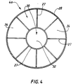
- the partition of vertical partitions is made up of a set of sheets 27 welded either to each other or to the wall 28 circular of the stripping chamber 4a.
- This set defines, in top view, a plurality of cells 30 elementary stripping, first of all an area central 32 substantially concentric with the wall 28 of the stripping enclosure, at the periphery of which extend from truncated angular sectors 34.
- the area central 32, and the truncated angular sectors 34 have substantially equal sections.
- the sheets welded to the walls of the stripping chamber are arranged along diameters thereof, so that the elementary stripping cells are parts of the stripping enclosure.
- a means 20 'of uniform distribution of the stripping fluid is inserted between the lower end of the partitions vertical 26 and diffusers 8 of said fluid. It is similar to means 20 of homogeneous distribution of particles to be stripped, shown in Figure 3, and it does will therefore not be described again.
- This means for distributing the stripping fluid is disposed at a distance D 2 from the fluid supply line, and it further extends over a height H 3 of the stripping enclosure.
- the distance D 2 is for example equal to 0.1H, but it can be between 0.05H and 0.2H.
- the height H 3 is for example equal to H / 10, but it can be between 0.05H and 0.2H.
- the means 20 'of distribution is shown immediately below the partitions vertical, but it can be spaced from a distance of for example up to 0.1H.
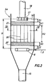
- FIG. 5 illustrates the application of the invention to the regeneration enclosure 9 of FIG. 1.
- the particles deactivated catalyst from the containment stripping 4a are directed towards the regeneration enclosure 9 via a conduit 10. It is provided, at the outlet of this conduit, a means of homogeneous distribution of particles, which consists of an extension 36 of the downstream part of the duct, curved upwards. This extension allows the trajectories 37 followed by the catalyst to be distributed along the entire section of enclosure 9.
- the catalyst is maintained in bed conditions dense fluidized, between the conduit 10 and the device supply 13 with regeneration fluid.
- Partition continuous vertical partitions 26, similar to that described with reference to Figures 2 and 4 extends over a substantial fraction of the height H 'of this fluidized bed dense, for example equal to 2H '/ 3 but which can be understood between H '/ 2 and 9H' / 10.
- This partition defines a plurality 38 independent regeneration cells which, due to their high height / diameter ratio, ensure good homogeneity of the residence time of the catalyst particles.
- injectors 13 evenly distributed at the end of line 12 fluid supply, are extended by diffusers not shown, which allow the fluid to disperse on along the entire cross section of the enclosure.
- the catalyst regenerated is discharged to the base of enclosure 9 and is directed by line 3 towards the base of the column of reaction.
- the invention is not limited to the forms of implementation artwork described above. Those skilled in the art can adapt the subject of the invention to any other type of stripper, like ring strippers, or any other type of regenerator.
- the invention further relates to any partition of continuous vertical partitions, of a any geometry.
- the tests are carried out in a commercial unit at a pressure of approximately 2.10 5 Pa (2 bars).
- the feedstock treated is a mixture of vacuum distillate and atmospheric residue.
- test No 1 the stripping enclosure comprises baffles of conventional structure, while in tests No 2 and 3, the stripping enclosure comprises continuous vertical partitions as shown in Figure 4 described above.
- Test # 2 Test # 3 Stripping steam (t / h) 3 3 1.5
- Regenerator temperature (° C) 740 690 704 C / O report 5.0 6.4 5.7 ⁇ Coke (% by weight) 0.9 0.7 0.1 Coke hydrogen (% by weight) 7.5 6.0 6.6
- Post-combustion (° C) 27 5 11 Addition of fresh catalyst particles (t / d) 5 3.1 4
- the efficiency of stripping increases the ratio C / O (mass ratio of catalyst C in contact with the load O) within the device and therefore increase the load conversion, by putting it in presence of a larger number of active sites of the particles of catalyst.
- the stability of the catalyst particles of the device is increased, which reduces the addition daily fresh catalyst particles and racking daily deactivated catalyst particles, while maintaining the adequate volume of particles in the device.
- Test No. 3 was conducted with stripping vapor reduced by around 1.5 t / h. The results are also satisfactory vis-à-vis those of test No. 1. So the stripping according to the invention allows a reduction in the consumption of stripping steam, while improving its efficiency compared to the prior art. In addition, this translates into energy savings and reduced volume of polluted water resulting from the condensation of the steam used for stripping.
- the homogenization of the residence time of the particles of catalyst in stripper and improved contact between the stripping fluid and the particles translate in particular by reducing the training of hydrocarbons to the regenerator, a drop in the content into hydrogen coke and the elimination of the phenomenon of afterburner.
Abstract
Description
La présente invention concerne les opérations de traitement des particules de catalyseur en craquage catalytique à l'état fluide, et plus particulièrement les opérations de strippage et de régénération du catalyseur. Elle a plus précisément pour objet un dispositif et un procédé pour traiter, par un fluide circulant à contre-courant, les particules de catalyseur en lit fluidisé dense, afin notamment d'éliminer les polluants entraínés avec ces particules et/ou adsorbés sur celles-ci.The present invention relates to the operations of treatment of cracked catalyst particles catalytic in the fluid state, and more particularly the stripping and regeneration of the catalyst. More specifically, it relates to a device and a process for treating, with a fluid circulating against the current, the particles of catalyst in a dense fluidized bed, in particular to eliminate the pollutants entrained with these particles and / or adsorbed thereon.
De manière connue en soi, l'industrie pétrolière a recours à des procédés de conversion tels que le procédé de craquage catalytique en lit fluidisé (en anglais, Fluid Catalytic Cracking, ou encore procédé FCC). Dans ces procédés, des molécules d'hydrocarbures à haut poids moléculaire et à point d'ébullition élevé sont scindées en molécules plus petites, qui peuvent bouillir dans des intervalles de températures plus faibles, convenant à l'usage recherché (voir à cet effet, notamment, la demande de brevet français n° 2.628.436 au nom de la Demanderesse).In known manner, the petroleum industry has use of conversion methods such as the catalytic cracking in a fluidized bed (in English, Fluid Catalytic Cracking, or FCC process). In these processes, high-weight hydrocarbon molecules molecular and high boiling point are split into smaller molecules, which can boil in lower temperature intervals suitable for the intended use (see for this purpose, in particular, the French patent application No. 2,628,436 in the name of the Applicant).
Les particules de catalyseur se désactivent rapidement pendant le court laps de temps où elles sont en contact avec la charge, essentiellement du fait d'une adsorption d'hydrocarbures, ainsi que d'un dépôt de coke et d'autres contaminants sur leurs sites actifs. Il est donc nécessaire de stripper en continu les grains désactivés de catalyseur, pour en récupérer les hydrocarbures adsorbés et entraínés dans les volumes vides séparant ces grains, puis de régénérer ces grains de catalyseur, également en continu, par une combustion contrôlée du coke, dans une section de régénération à un ou plusieurs étages. Les grains de catalyseur sont ensuite recyclés vers la zone réactionnelle. Ces deux opérations de traitement, que sont le strippage et la régénération, s'effectuent en lit fluidisé dense, c'est à dire de densité comprise entre 400 et 800 kg/m3.Catalyst particles are rapidly deactivated during the short time they are in contact with the charge, mainly due to adsorption of hydrocarbons, as well as a deposit of coke and other contaminants on their active sites . It is therefore necessary to continuously stripped the deactivated grains of catalyst, to recover the adsorbed hydrocarbons and entrained in the empty volumes separating these grains, then to regenerate these grains of catalyst, also continuously, by controlled combustion of coke, in a regeneration section with one or more stages. The catalyst grains are then recycled to the reaction zone. These two treatment operations, namely stripping and regeneration, are carried out in a dense fluidized bed, that is to say with a density of between 400 and 800 kg / m 3 .
Toutefois, l'utilisation de ces lits fluidisés industriels de grande taille présente un certain nombre de difficultés.However, the use of these fluidized beds large industrial companies presents a number of difficulties.
Ainsi, il est nécessaire d'y opérer un brassage conséquent, afin de casser les accumulations de solide ou de fluide, et d'en assurer ainsi un mélange intime. En revanche, ce brassage a pour effet d'augmenter de manière indésirable le temps de séjour des particules dans la zone de traitement. Or, ce temps de séjour est particulièrement critique et doit être sensiblement le même pour les différentes particules.So, it is necessary to operate a mixing therefore, in order to break down the build-up of solid or fluid, and thus ensure an intimate mixture. In however, this mixing has the effect of increasing undesirable the residence time of particles in the area treatment. However, this residence time is particularly critical and should be much the same for them different particles.
Selon une technique usuelle, le strippage s'effectue dans une enceinte située à la sortie de la colonne de réaction, que celle-ci soit ascendante ou descendante, après séparation des effluents issus de la zone réactionnelle.According to a usual technique, stripping is carried out in an enclosure located at the outlet of the column reaction, whether ascending or descending, after separation of effluents from the reaction zone.
Au niveau inférieur de ladite enceinte, le strippage s'opère en phase fluidisée dense. Un fluide gazeux, de préférence très polaire (vapeur d'eau par exemple), est injecté à la base de l'enceinte et lave à contre-courant la suspension de grains désactivés de catalyseur. Il permet le déplacement et la récupération des hydrocarbures, qui sont soit entraínés dans les espaces vides laissés entre les grains de catalyseurs désactivés, soit adsorbés à leur surface. Finalement, les grains de catalyseur strippés sont évacués par une sortie se situant à la base de l'enceinte.At the lower level of said enclosure, stripping operates in dense fluidized phase. A gaseous fluid, of preferably very polar (water vapor for example), is injected at the base of the enclosure and backwashing the suspension of deactivated grains of catalyst. It allows the displacement and recovery of hydrocarbons, which are either entrained in the empty spaces left between the grains of deactivated catalysts, or adsorbed to their area. Finally, the stripped catalyst grains are evacuated by an outlet located at the base of the enclosure.
Le temps de séjour des particules de catalyseur dans le strippeur doit être le plus homogène possible. En effet, si le catalyseur séjourne pendant une durée insuffisante dans le strippeur, un excès d'hydrocarbures reste déposé à sa surface et est ensuite envoyé au régénérateur. Ceci conduit à une température de régénération trop élevée, nuisible au bon fonctionnement de l'unité, au détriment de la quantité d'hydrocarbures valorisables récupérés dans la zone de fractionnement.The residence time of the catalyst particles in the stripper must be as homogeneous as possible. Indeed, if the catalyst remains for an insufficient time in the stripper, an excess of hydrocarbons remains deposited at its surface and is then sent to the regenerator. This leads at too high a regeneration temperature, harmful to correct operation of the unit, to the detriment of the quantity recoverable hydrocarbons recovered in the area of splitting.
En revanche, si la durée de séjour du catalyseur est trop importante, cela oblige, afin de garder un débit de catalyseur constant, à surdimensionner l'enceinte de strippage, ce qui entraíne un encombrement et un surcoût indésirables.On the other hand, if the residence time of the catalyst is too large, this requires, in order to keep a flow of constant catalyst, to oversize the enclosure of stripping, which leads to congestion and an additional cost undesirable.
En ce qui concerne la régénération, celle-ci a lieu dans une enceinte reliée au bas du strippeur par un tube incliné. La régénération se déroule usuellement à contre-courant, au sein d'un lit fluidisé dense, au sommet duquel est introduit le catalyseur coké à régénérer et à la base duquel un gaz de combustion riche en oxygène, par exemple de l'air, est admis par une soufflante.Regarding regeneration, this takes place in an enclosure connected to the bottom of the stripper by an inclined tube. Regeneration usually takes place against the current, within a dense fluidized bed, at the top of which is introduced the coked catalyst to be regenerated and at the base of which a gas of combustion rich in oxygen, for example air, is allowed by a blower.
Ici encore, le temps de séjour des particules de catalyseur dans l'enceinte de régénération doit être le plus homogène possible.Here again, the residence time of the particles of catalyst in the regeneration enclosure should be the most homogeneous possible.
En effet, si le catalyseur séjourne un temps insuffisant dans le régénérateur, la combustion du coke déposé à sa surface est incomplète, ce qui présente deux inconvénients :
- d'une part, le catalyseur n'est que partiellement régénéré, de sorte que ses propriétés sont limitées par l'obstruction d'un nombre important de ses sites actifs;
- d'autre part, le catalyseur aura emmagasiné une quantité de chaleur insuffisante, ce qui a pour conséquence une mauvaise vaporisation de la charge dans la colonne de réaction, et donc un craquage incomplet.
- on the one hand, the catalyst is only partially regenerated, so that its properties are limited by the obstruction of a large number of its active sites;
- on the other hand, the catalyst will have stored an insufficient amount of heat, which results in poor vaporization of the feed in the reaction column, and therefore an incomplete cracking.
En revanche, si le catalyseur est soumis trop longtemps aux conditions de régénération, et en particulier à la température élevée qui les caractérise, il court de forts risques d'être endommagé.On the other hand, if the catalyst is subjected for too long the regeneration conditions, and in particular the high temperature which characterizes them, it runs strong risk of being damaged.
Les problèmes liés à la circulation à contre-courant d'un fluide ascendant et d'un flux de particules descendantes sont bien connus en soi. Ils ont d'ores et déjà été résolus dans certains domaines techniques, différents de celui du craquage catalytique.Problems with counter-current traffic of an ascending fluid and a flow of particles descendants are well known per se. They already have been resolved in certain technical areas, different from that of catalytic cracking.
Ainsi, le brevet U.S. 2 781 301 propose, dans une enceinte de purification d'huiles circulant à contre-courant de particules d'adsorbant, d'introduire une pluralité de cloisonnements internes verticaux. Le but recherché est la diminution des phénomènes de rétromélange (tendance des particules à se laisser entrainer vers le haut par le fluide ascendant), ainsi qu'un meilleur contrôle de la vitesse de passage.Thus, U.S. Patent 2,781,301 proposes, in a oil purification chamber circulating against the current adsorbent particles, introduce a plurality of vertical internal partitions. The aim is to decrease in back-mixing phenomena (trend of particles to be carried upwards by the fluid ascending), as well as better speed control passage.
Néanmoins, les problèmes rencontrés dans le domaine du traitement des huiles sont entièrement différents de ceux du craquage catalytique. En effet, les lits fluidisés denses gaz / particules sont beaucoup plus turbulents que les mélanges huile / particules, ne serait-ce que de par la grande viscosité des huiles. Les problèmes de rétromélange, de courant de recirculation, sont nettement plus importants dans ces lits fluidisés et ils s'y produisent de manière plus soudaine et plus désordonnée.However, the problems encountered in the field of treatment of oils are entirely different from those of catalytic cracking. Indeed, dense fluidized beds gases / particles are much more turbulent than oil / particle mixtures, if only because of high viscosity of oils. The problems of back mixing, of recirculation current, are significantly higher in these fluidized beds and they occur there so more sudden and more disorderly.
Le fait que le traitement s'effectue en lit fluidisé est ainsi la cause d'importants problèmes supplémentaires. On citera également des problèmes de ségrégation liés notamment à la formation de bulles de vapeur montante de plus en plus grosses. Par ailleurs, l'utilisation d'internes dans les unités de craquage catalytique est particulièrement difficile, en raison des phénomènes d'abrasion liés à la vitesse très élévée de circulation des particules de catalyseur (plusieurs tonnes par minute).The fact that the treatment is carried out in a fluidized bed is thus causing significant additional problems. We will also cite segregation problems linked in particular to the formation of rising vapor bubbles more and more big. In addition, the use of interns in catalytic cracking units is particularly difficult, due to the abrasion phenomena linked to the very high speed of circulation of particles of catalyst (several tonnes per minute).
Tout ceci fait que le strippage et la régénération des grains de catalyseur de craquage catalytique au moyen d'un gaz circulant à contre-courant demeurent particulièrement problématiques, bien que diverses solutions aient déjà été proposées.All this means that the stripping and regeneration of grains of catalytic cracking catalyst using a gases flowing against the current remain particularly problematic, although various solutions have already been proposed.
On citera notamment l'interposition, dans la phase fluidisée dense de catalyseur, d'obstacles qui se présentent par exemple sous la forme de chicanes en V renversé. Ces obstacles ont pour but de briser les grosses bulles de vapeur, évitant ainsi le renardage, et de casser les courants de recirculation, ce qui limite le rétromélange.We will cite in particular the interposition, in the phase dense fluidized catalyst, obstacles that arise for example in the form of inverted V baffles. These obstacles are intended to break the large bubbles of steam, thus avoiding foxing, and breaking them recirculation currents, which limits the back mixing.
Toutefois, cette solution ne résoud que partiellement le problème de l'homogénéisation du temps de séjour, et présente un inconvénient supplémentaire: ces obstacles, qui incluent le plus souvent des parois inclinées, créent une ségrégation entre la vapeur et le solide. En effet, le catalyseur a tendance à s'accumuler au voisinage des parois inclinées, tandis que la vapeur remontant s'accumule dans les V renversés, créant ainsi une zone morte. De plus, de tels internes sont généralement sujets à l'érosion par le flux de particules.However, this solution only partially solves the problem of homogenization of the residence time, and has an additional disadvantage: these obstacles, which most often include inclined walls, create a segregation between vapor and solid. Indeed, the catalyst tends to accumulate near the walls inclined, while the rising steam accumulates in the V's overturned, thus creating a dead zone. Over such internals are generally subject to erosion by the particle flow.
Le brevet U.S. 2 481 439 propose une enceinte de strippage comportant une pluralité de garnissages transversaux espacés les uns des autres, chacun de ces garnissages étant constitué de grilles empilées les unes au dessus des autres et soudées de manière à former des cellules verticales.U.S. Patent 2,481,439 provides an enclosure for stripping comprising a plurality of linings spaced apart from each other, each of these linings consisting of grids stacked one at a time above others and welded so as to form vertical cells.
Néanmoins, les espaces présents entre ces garnissages s'avèrent être des zones de turbulences privilégiées, où se produisent, de manière désordonnée, des tourbillons et du rétromélange. Les particules de catalyseur ne progressent donc pas de manière continue et uniforme, ce qui entraíne un défaut d'homogénéité du temps de séjour des particules dans l'enceinte de strippage.However, the spaces between these linings turn out to be areas of privileged turbulence, where randomly produce vortices and back-mixing. The catalyst particles do not progress so not continuously and uniformly, which results in a lack of uniformity of the residence time of the particles in the stripping enclosure.
Afin de pallier les différents inconvénients de la technique antérieure évoqués ci-dessus, la présente invention a pour but de proposer un dispositif et un procédé pour le traitement de particules solides fluidisées, qui permettent une homogénéisation du temps de séjour de ces particules dans la zone de traitement, tout en réalisant une mise en contact intime entre le solide et le fluide de traitement.In order to overcome the various disadvantages of the prior art mentioned above, the present object of the invention is to provide a device and a method for the treatment of fluidized solid particles, which allow a homogenization of the residence time of these particles in the treatment area, while achieving intimate contact between the solid and the fluid treatment.
A cet effet, la présente invention a pour objet un dispositif pour le strippage ou la régénération de particules de catalyseur, dans une unité de craquage catalytique à l'état fluide, par traitement desdites particules en lit fluidisé dense circulant de haut en bas au sein d'une enceinte de traitement et à contre-courant d'un fluide gazeux de traitement, ledit dispositif comprenant:
- au moins un conduit pour l'introduction des particules à traiter à la partie supérieure du lit fluidisé dense;
- au moins un conduit raccordé à la base de l'enceinte, pour l'évacuation des particules traitées à la base du lit fluidisé dense;
- au moins une ligne d'alimentation en fluide gazeux de traitement, débouchant à la base de l'enceinte ;
- at least one conduit for the introduction of the particles to be treated into the upper part of the dense fluidized bed;
- at least one conduit connected to the base of the enclosure, for the evacuation of the treated particles at the base of the dense fluidized bed;
- at least one supply line for gaseous treatment fluid, opening at the base of the enclosure;
Ce dispositif permet de réaliser les objectifs précités.This device makes it possible to achieve the aforementioned objectives.
Il permet tout d'abord d'homogénéiser le temps de séjour des particules de catalyseur dans l'enceinte de traitement.First of all, it makes it possible to standardize the residence time catalyst particles in the treatment enclosure.
En effet, les cellules de traitement indépendantes créées par l'interposition de cloisonnements verticaux continus s'étendent sur une majeure partie de la longueur du lit fluidisé dense de particules à traiter. Ces cellules possèdent, par conséquent, un rapport hauteur / diamètre élevé, qui est bien supérieur à celui des enceintes classiques. De la sorte, les courants de recirculation et le rétromélange, qui sont d'autant plus importants que ce rapport est faible, sont très nettement atténués: au sein de chaque cellule, il règne un écoulement de type piston, qui permet à l'ensemble des particules solides de progresser de manière uniforme.Indeed, independent treatment cells created by the interposition of vertical partitions continuous extend over most of the length of the dense fluidized bed of particles to be treated. These cells therefore have a height / diameter ratio high, which is much higher than that of pregnant classics. In this way, the recirculation currents and the retromix, which are all the more important as this ratio is low, are very clearly attenuated: within each cell, there is a piston type flow, which allows all solid particles to progress by uniformly.
De plus, la ségrégation entre la vapeur montante et le solide descendant est évitée, dans la mesure où, contrairement aux techniques de l'art antérieur, les cellules de traitement élémentaires de l'invention sont assimilables à autant d'enceintes vides. L'invention évite donc l'utilisation d'obstacles inclinés, sur les parois desquels le catalyseur est susceptible de s'accumuler.In addition, the segregation between the rising vapor and the solid descending is avoided, to the extent that, unlike the techniques of the prior art, the elementary processing cells of the invention are comparable to as many empty speakers. The invention avoids therefore the use of inclined obstacles on the walls from which the catalyst is likely to accumulate.
Enfin, les parois desdites cellules étant verticales, le dispositif conforme à la présente invention n'est pas sujet à l'érosion par le flux de particules de catalyseur, contrairement à de nombreux dispositifs de l'art antérieur. Finally, the walls of said cells being vertical, the device according to the present invention is not subject erosion by the flow of catalyst particles, unlike many devices of the prior art.
L'invention a également pour objet un procédé pour le strippage ou la régénération de particules de catalyseur en lit fluididé dense, dans une enceinte de traitement d'une unité de craquage cataytique à l'état fluide, ce procédé comprenant au moins les étapes suivantes:
- une étape d'introduction des particules à traiter dans l'enceinte de traitement, à la partie supérieure du lit fluidisé dense;
- une étape de traitement desdites particules circulant de haut en bas dans l'enceinte de traitement, sous forme de lit fluidisé dense et à contre-courant d'un fluide gazeux de traitement introduit à la base dudit lit fluidisé dense;
- une étape d'évacuation des particules traitées hors de l'enceinte de traitement, à la base du lit fluidisé dense;
- a step of introducing the particles to be treated into the treatment enclosure, at the top of the dense fluidized bed;
- a step of treating said particles flowing from top to bottom in the treatment enclosure, in the form of a dense fluidized bed and against the flow of a gaseous treatment fluid introduced at the base of said dense fluidized bed;
- a step of evacuating the treated particles from the treatment enclosure, at the base of the dense fluidized bed;
ce procédé étant caractérisé en ce que, lors de l'étape de traitement, les particules de catalyseur et ledit fluide gazeux passent au travers d'une pluralité de cellules élémentaires de traitement, indépendantes les unes des autres, définies à l'intérieur de ladite enceinte par une partition de cloisonnements verticaux continus, qui divisent le lit fluidisé dense en une pluralité de lits fluidisés denses contigus, s'écoulant de haut en bas de manière indépendante les uns par rapport aux autres.this process being characterized in that, during the step treatment, catalyst particles and said fluid gases pass through a plurality of cells elementary processing, independent of each others, defined inside said enclosure by a partition of continuous vertical partitions, which divide the dense fluidized bed in a plurality of fluidized beds dense contiguous, flowing up and down so independent from each other.
Au sens de la présente invention, on entend, par lit fluidisé dense, un lit fluidisé dont la densité est comprise entre 400 et 800 kg/m3.For the purposes of the present invention, the term “dense fluidized bed” means a fluidized bed whose density is between 400 and 800 kg / m 3 .
Les cloisonnements verticaux conformes à l'invention peuvent s'étendre sur une hauteur comprise entre 50 et 90%, et de préférence entre 60 et 80% de la hauteur du lit fluidisé dense.Vertical partitions according to the invention can extend over a height between 50 and 90%, and preferably between 60 and 80% of the height of the bed dense fluidized.
De manière avantageuse, le nombre de cellules de traitement élémentaires définies par les cloisonnements verticaux conformes à l'invention est tel que le rapport entre leur hauteur et leur diamètre hydraulique est compris entre 3 et 10 et, de préférence, entre 5 et 7.Advantageously, the number of cells of elementary processing defined by the partitions vertical according to the invention is such that the ratio between their height and their hydraulic diameter is included between 3 and 10 and preferably between 5 and 7.
Compte tenu des dimensions usuelles des enceintes de traitement, ce nombre de cellules de traitement élémentaires est compris entre 2 et 50, de manière préférée entre 3 et 40 et, de manière encore plus préférée, entre 5 et 20.Taking into account the usual dimensions of the processing, this number of elementary processing cells is between 2 and 50, preferably between 3 and 40 and, even more preferably, between 5 and 20.
En effet, si le nombre de cellules est trop petit, leur rapport hauteur / diamètre reste faible, ce qui empêche une bonne homogénéisation du temps de séjour des particules de catalyseur.Indeed, if the number of cells is too small, their height / diameter ratio remains low, which prevents a good homogenization of the residence time of the particles of catalyst.
En revanche, si les cellules élémentaires sont trop nombreuses, et donc de faible diamètre, leur section transversale est susceptible d'être entièrement occupée par une bulle de vapeur montante, ce qui empêcherait alors un contact correct entre le solide et la vapeur.On the other hand, if the elementary cells are too numerous, and therefore of small diameter, their section transverse is likely to be fully occupied by a rising vapor bubble, which would prevent a correct contact between solid and vapor.
De manière avantageuse, en particulier lorsque le conduit d'introduction des particules à traiter présente un diamètre beaucoup plus faible que celui de l'enceinte, au moins un moyen de distribution homogène des particules est disposé au-dessus de la partition de cloisonnements verticaux.Advantageously, in particular when the conduit for introducing the particles to be treated has a much smaller diameter than that of the enclosure, at least one means of homogeneous particle distribution is arranged above the partition partition vertical.
De tels moyens de distribution peuvent être placés soit au niveau de la sortie du conduit d'introduction des particules de catayseur, soit dans le lit fluidisé dense lui-même, et ils peuvent être utilisés alternativement ou complémentairement.Such distribution means can be placed either at the outlet of the conduit for introducing the catalytic particles, either in the dense fluidized bed itself, and they can be used alternately or additionally.
De manière analogue, au moins un moyen de distribution homogène de fluide de traitement peut être disposé au-dessous de la partition de cloisonnements verticaux. Ce ou ces moyens de distribution peuvent être placés soit au niveau de la sortie de la ligne d'alimentation en fluide, soit dans le lit fluidisé dense, et ils peuvent être utilisés alternativement ou complémentairement.Similarly, at least one means of distribution homogeneous treatment fluid can be arranged underneath of the partitioning of vertical partitions. This or these distribution means can be placed either at level of the outlet of the fluid supply line, either in the dense fluidized bed, and they can be used alternately or in addition.
Grâce à de tels moyens de distribution, les particules et le fluide de strippage se répartissent de manière uniforme sur toute la section de l'enceinte de strippage. Chaque cellule élémentaire se trouve ainsi bien alimentée à la fois en particules et en fluide. Le strippage au sein de chacune des cellules est alors particulièrement satisfaisant, du fait de l'écoulement de type piston qui y règne.Thanks to such distribution means, the particles and the stripping fluid are distributed so uniform over the entire section of the stripping chamber. Each elementary cell is thus well supplied with both in particles and in fluid. Stripping within each cell is then particularly satisfactory, due to the piston type flow which reign.
Selon un mode de réalisation, ces moyens de distribution homogène sont susceptibles sont aptes à orienter à leur sortie les particules de catalyseur ou le fluide selon deux directions différentes. Environ 50% des particules sont déviées dans une première direction et les 50% restants sont déviées selon une seconde direction formant un angle de 10 à 90 degrés avec la première direction. Il en est de même pour le fluide au-dessus de sa ligne d'alimentation.According to one embodiment, these distribution means homogeneous are likely are able to orient to their exit the catalyst particles or the fluid in two different directions. About 50% of the particles are deviated in a first direction and the remaining 50% are deflected in a second direction forming an angle of 10 to 90 degrees with the first direction. It is the same for the fluid above its supply line.
Les moyens de distribution peuvent être constitués par l'assemblage de tôles plissées coupées transversalement par rapport à leurs plans. Ces tôles plissées peuvent être perforées, striées ou rugueuses, et sont assemblées de façon telle que l'arête de plissure de chaque tôle forme un angle de sensiblement 45 à 135 degrés avec l'arête de plissure de la tôle adjacente. Selon un mode particulièrement préféré de l'invention, cet angle est de 90 degrés, définissant ainsi des réseaux de canaux croisés à angle droit. Ces croisements permettent avantageusement un contact étroit entre le fluide et les particules à l'intérieur du garnissage.The distribution means can be constituted by the assembly of pleated sheets cut transversely by compared to their plans. These pleated sheets can be perforated, striated or rough, and are assembled in a way such that the pleat edge of each sheet forms an angle substantially 45 to 135 degrees with the pleat edge of the adjacent sheet. According to a particularly preferred mode of invention, this angle is 90 degrees, thus defining networks of channels crossed at right angles. These crosses advantageously allow close contact between the fluid and particles inside the lining.
La disposition des tôles favorise la distribution homogène des particules ou du fluide. En particulier, dans la forme de réalisation décrite ci-dessus, 50% des particules de catalyseur (ou du fluide) sont déviées à chaque intersection formée par les arêtes de plissures d'une première tôle avec les arêtes de plissures d'une seconde tôle adjacente.The arrangement of the sheets promotes distribution homogeneous particles or fluid. In particular, in the embodiment described above, 50% of catalyst particles (or fluid) are diverted to each intersection formed by the pleat edges of a first sheet with one second pleat edges adjacent sheet metal.
Diverses structures d'élément de garnissage employées dans d'autres domaines peuvent être utilisées. Notamment, les mélangeurs statiques tels que ceux commercialisés par les Sociétés dénommées Sulzer-SMV ou Kenics, bien que non destinés à une telle application, peuvent être adaptés et modifiés pour permettre une distribution homogène des particules ou du fluide.Various packing element structures used in other areas can be used. Especially, static mixers such as those sold by Companies named Sulzer-SMV or Kenics, although not intended for such an application, can be adapted and modified to allow a homogeneous distribution of particles or fluid.
D'autres caractéristiques et avantages de l'invention
apparaítront à la lecture de la description qui va suivre
d'une mise en oeuvre de l'invention. Dans cette description,
on se réfèrera aux dessins annexés, dans lesquels:
Le dispositif de craquage catalytique par le procédé FCC
représenté schématiquement sur la figure 1 est d'un type
connu en soi. Il comprend essentiellement une colonne 1,
dite élévateur de charge, alimentée à sa base, par la ligne
2, en charge à traiter et, par le conduit 3, en particules
d'un catalyseur de craquage. Un gaz élévateur, par exemple
de la vapeur d'eau, est introduit dans la colonne 1 par la
ligne 35.The catalytic cracking device by the FCC process
shown schematically in Figure 1 is of a type
known per se. It basically includes a
La colonne 1 débouche à son sommet dans une capacité 4,
où s'effectue la séparation de la charge craquée et à la
base de laquelle les particules désactivées de catalyseur
sont strippées dans une enceinte de strippage 4a.
Dans le cas présent, l'enceinte de strippage 4a est excentrée par rapport à la colonne. Toutefois, elle peut revêtir d'autres formes et positions. Par exemple, cette enceinte peut être concentrique à la colonne, ce qui nécessite un dessin adapté des éléments.In this case, the enclosure of a stripping 4 is eccentric with respect to the column. However, it can take other forms and positions. For example, this enclosure can be concentric with the column, which requires a suitable drawing of the elements.
La charge traitée est séparée dans un cyclone 5, qui est
logé dans la capacité 4, au sommet de laquelle est prévue
une ligne d'évacuation 6 de la charge craquée, tandis que
les particules désactivées se déplacent par gravité vers
l'enceinte de strippage 4a. Une ligne 7 alimente en fluide
de strippage, généralement de la vapeur d'eau, des
injecteurs ou diffuseurs de gaz de fluidisation 8 disposés
régulièrement à la base de l'enceinte de strippage 4a. Le
strippage s'effectue donc en lit fluidisé dense, à contre-courant
des particules.The treated charge is separated in a
Les particules désactivées de catalyseur ainsi strippées
sont évacuées à la base de l'enceinte de strippage 4a vers
un régénérateur 9, par l'intermédiaire d'un conduit 10, sur
lequel est prévue une vanne de régulation 11. Dans le
régénérateur 9, le coke déposé sur les particules du
catalyseur est brûlé à l'aide d'air, injecté à la base du
régénérateur par une ligne 12, qui alimente des injecteurs
13 régulièrement espacés. Les particules du catalyseur
traité, entraínées par le gaz de combustion, sont séparées
par des cyclones 14, d'où le gaz de combustion est évacué
par une ligne 15, tandis que les particules de catalyseur
sont rejetées vers la base du régénérateur 9, d'où elles
sont recyclées par le conduit 3, équipé d'une vanne de
régulation 16, vers l'alimentation de l'élévateur 1.The deactivated particles of catalyst thus stripped
are discharged at the base of the stripping
Les caractéristiques dimensionnelles et opératoires d'un tel dispositif sont habituellement les suivantes :
- hauteur de la partie réactionnelle de l'élévateur 1: 5 à 40 mètres,
- température de la charge à craquer : 75 à 150°C,
- débit d'alimentation de l'élévateur 1 en charge à traiter : 1000 à 20 000 tonnes par jour,
- débit d'alimentation de l'élévateur 1 en catalyseur : 3 à 50 tonnes par minute,
- temps de craquage dans l'élévateur 1 : 0,1 à 10 secondes,
- température de régénération du catalyseur : 650 à 900°C,
- temps de séjour du catalyseur dans le régénérateur 9 : 5 à 20 mn.
- height of the reaction part of the elevator 1: 5 to 40 meters,
- temperature of the load to be cracked: 75 to 150 ° C,
- feed rate of the
elevator 1 in charge to be treated: 1000 to 20,000 tonnes per day, - supply rate of the
elevator 1 with catalyst: 3 to 50 tonnes per minute, - cracking time in elevator 1: 0.1 to 10 seconds,
- catalyst regeneration temperature: 650 to 900 ° C,
- residence time of the catalyst in the regenerator 9: 5 to 20 min.
Comme le montre la figure 2, le dispositif conforme à
l'invention peut être utilisé dans l'enceinte de strippage
4a de la figure 1. Cette enceinte 4a comprend à son sommet
un conduit 18 permettant l'introduction des particules de
catalyseur désactivées à stripper et, à sa base, une ligne 7
alimentant des diffuseurs 8 en un fluide gazeux de
strippage.As shown in Figure 2, the device according to
the invention can be used in the stripping
Un lit fluidisé dense de catalyseur s'étend donc sur une
hauteur H de l'enceinte, entre le conduit 18 d'introduction
des particules et la ligne 7 d'alimentation en fluide.A dense fluidized bed of catalyst therefore extends over a
height H of the enclosure, between the
Un premier moyen de distribution homogène du catalyseur
descendant est prévu au niveau de la sortie du conduit 18.
Ce moyen est constitué par un distributeur annulaire 17, qui
distribue les particules par des ouvertures latérales 19.A first means of homogeneous distribution of the catalyst
descending is provided at the outlet of
Au-dessous du conduit, et à une distance D1 de celui-ci, un second moyen 20 de distribution homogène des particules est disposé au sein même du lit fluidisé dense et s'étend sur une hauteur H1 de l'enceinte de strippage. La distance D1 est par exemple égale à 0,1H, où H est la hauteur totale du lit fluidisé dense, mais peut être comprise entre 0,05H et 0,2H. La hauteur H1 est par exemple égale à 0,1H, mais peut être comprise entre 0,05H et 0,2H.Below the duct, and at a distance D 1 therefrom, a second means 20 for homogeneous distribution of the particles is disposed within the dense fluidized bed itself and extends over a height H 1 of the stripping enclosure. . The distance D 1 is for example equal to 0.1H, where H is the total height of the dense fluidized bed, but can be between 0.05H and 0.2H. The height H 1 is for example equal to 0.1H, but can be between 0.05H and 0.2H.
Comme le montre la figure 3, le moyen 20 de distribution
homogène placé dans le lit fluidisé dense est constitué de
tôles plissées coupées transversalement par rapport à leur
plan. Ces tôles plissées sont assemblées de façon telle que
l'arête de la plissure 22 de chaque tôle forme un angle de
sensiblement 90 degrés avec l'arête de la plissure 22' de la
tôle adjacente. Ainsi, les plissures de chaque tôle
s'entrecroisent avec les plissures de la tôle adjacente et
constituent des cellules formant un réseau de canaux croisés
23, 24. La section des cellules est choisie afin d'éviter
tout phénomène d'obstruction par les particules.As shown in FIG. 3, the distribution means 20
homogeneous placed in the dense fluidized bed consists of
pleated sheets cut transversely to their
plan. These pleated sheets are assembled in such a way that
the edge of the
Dans le cas présenté, les tôles ondulées sont soudées
les unes aux autres au niveau de l'arête des plissures 22,
22'. Les particules de catalyseur pénètrent et sont guidées
dans les canaux 23, 24. L'agencement des canaux permet de
dévier les particules à chaque intersection formée par les
plissures d'une première tôle avec les plissures d'une
seconde tôle adjacente, entraínant ainsi une distribution
homogène des particules de catalyseur.In the case presented, the corrugated sheets are welded
to each other at the level of the
En faisant à nouveau référence à la figure 2, une
partition de cloisonnements verticaux continus 26 est
disposée au-dessous des moyens 20 de distribution et s'étend
sur une hauteur H2 du lit fluidisé dense. La hauteur H2 est
par exemple égale à 2H/3, mais elle peut être comprise entre
H/2 et 9H/10. Sur la figure 2, les cloisonnements sont
représentés immédiatement au-dessous du moyen 20 de
distribution, mais ils peuvent en être espacés d'une
distance allant par exemple jusqu'à 0,1H.Referring again to Figure 2, a partition of continuous
Comme le montre la figure 4, la partition de
cloisonnements verticaux est constituée d'un ensemble de
tôles 27 soudées soit entre elles, soit avec la paroi 28
circulaire de l'enceinte de strippage 4a. Cet ensemble
définit, en vue de dessus, une pluralité de cellules de
strippage 30 élémentaires, à savoir tout d'abord une zone
centrale 32 sensiblement concentrique à la paroi 28 de
l'enceinte de strippage, à la périphérie de laquelle
s'étendent des secteurs angulaires tronqués 34. La zone
centrale 32, et les secteurs angulaires tronqués 34
possèdent des sections sensiblement égales.As shown in Figure 4, the partition of
vertical partitions is made up of a set of
Dans une variante de réalisation non représentée, les tôles soudées aux parois de l'enceinte de strippage sont disposées suivant des diamètres de celle-ci, de sorte que les cellules élémentaires de strippage sont des parties angulaires de l'enceinte de strippage.In an alternative embodiment not shown, the sheets welded to the walls of the stripping chamber are arranged along diameters thereof, so that the elementary stripping cells are parts of the stripping enclosure.
En faisant à nouveau référence à la figure 2, un moyen
20' de distribution homogène du fluide de strippage est
intercalé entre l'extrémité inférieure des cloisonnements
verticaux 26 et les diffuseurs 8 dudit fluide. Il est
semblable au moyen 20 de distribution homogène des
particules à stripper, représenté à la figure 3, et il ne
sera donc pas à nouveau décrit.Referring again to Figure 2, a means
20 'of uniform distribution of the stripping fluid is
inserted between the lower end of the partitions
vertical 26 and
Ce moyen de distribution du fluide de strippage est disposé à une distance D2 de la ligne d'alimentation de fluide, et il s'étend en outre sur une hauteur H3 de l'enceinte de strippage.This means for distributing the stripping fluid is disposed at a distance D 2 from the fluid supply line, and it further extends over a height H 3 of the stripping enclosure.
La distance D2 est par exemple égale à 0,1H, mais elle peut être comprise entre 0,05H et 0,2H. La hauteur H3 est par exemple égale à H/10, mais elle peut être comprise entre 0,05H et 0,2H.The distance D 2 is for example equal to 0.1H, but it can be between 0.05H and 0.2H. The height H 3 is for example equal to H / 10, but it can be between 0.05H and 0.2H.
Sur la figure 2, le moyen 20' de distribution est représenté immédiatement au-dessous des cloisonnements verticaux, mais il peut en être espacé d'une distance allant par exemple jusqu'à 0,1H.In FIG. 2, the means 20 'of distribution is shown immediately below the partitions vertical, but it can be spaced from a distance of for example up to 0.1H.
La figure 5 illustre l'application de l'invention à
l'enceinte de régénération 9 de la figure 1. Les particules
désactivées de catalyseur provenant de l'enceinte de
strippage 4a sont dirigées vers l'enceinte de régénération 9
par l'intermédiaire d'un conduit 10. Il est prévu, à la
sortie de ce conduit, un moyen de distribution homogène des
particules, qui est constitué par un prolongement 36 de la
partie aval du conduit, incurvé vers le haut. Ce
prolongement permet aux trajectoires 37 suivies par le
catalyseur de se répartir suivant toute la section de
l'enceinte 9.FIG. 5 illustrates the application of the invention to
the
Le catalyseur est maintenu dans des conditions de lit
fluidisé dense, entre le conduit 10 et le dispositif
d'alimentation 13 en fluide de régénération. Une partition
de cloisonnements verticaux continus 26, analogue à celle
décrite en référence aux figures 2 et 4, s'étend sur une
fraction substantielle de la hauteur H' de ce lit fluidisé
dense, par exemple égale à 2H'/3 mais pouvant être comprise
entre H'/2 et 9H'/10. Cette partition définit une pluralité
de cellules 38 de régénération indépendantes qui, du fait de
leur rapport hauteur / diamètre élevé, assurent une bonne
homogénéité du temps de séjour des particules de catalyseur.The catalyst is maintained in bed conditions
dense fluidized, between the
Afin d'assurer une meilleure répartition du fluide de
régénération 40 dans chacune des cellules, des moyens de
distribution homogène du fluide sont prévus à la sortie de
la ligne d'alimentation. A cet effet, des injecteurs 13,
régulièrement répartis à l'extrémité de la ligne 12
d'alimentation en fluide, sont prolongés par des diffuseurs
non représentés, qui permettent au fluide de se disperser
sur suivant toute la section transversale de l'enceinte.In order to ensure a better distribution of the
Après son passage au sein des cellules, le catalyseur
régénéré est évacué à la base de l'enceinte 9 et se trouve
dirigé par la ligne 3 vers la base de la colonne de
réaction.After passing through the cells, the catalyst
regenerated is discharged to the base of
L'invention n'est pas limitée aux formes de mise en oeuvre décrites ci-dessus. L'homme de l'art pourra ainsi adapter l'objet de l'invention à tout autre type de strippeur, comme les strippeurs annulaires, ou à tout autre type de régénérateur. L'invention vise en outre toute partition de cloisonnements verticaux continus, d'une géométrie quelconque.The invention is not limited to the forms of implementation artwork described above. Those skilled in the art can adapt the subject of the invention to any other type of stripper, like ring strippers, or any other type of regenerator. The invention further relates to any partition of continuous vertical partitions, of a any geometry.
Les exemples ci-après visent à illustrer l'invention et à souligner certains avantages apportés par le présent dispositif, dans le cas d'une enceinte de strippage.The examples below are intended to illustrate the invention and to point out certain advantages brought by the present device, in the case of a stripping enclosure.
Des tests représentatifs ont été réalisés afin d'évaluer l'efficacité d'un strippeur conforme à l'invention, comparativement avec un strippeur de l'art antérieur pourvu de chicanes.Representative tests were performed to assess the effectiveness of a stripper according to the invention, compared with a stripper of the prior art provided of baffles.
Les tests s'effectuent dans une unité commerciale à une pression d'environ 2.105 Pa (2 bars). La charge traitée est un mélange de distillat sous vide et de résidu atmosphérique.The tests are carried out in a commercial unit at a pressure of approximately 2.10 5 Pa (2 bars). The feedstock treated is a mixture of vacuum distillate and atmospheric residue.
Dans le test No 1, l'enceinte de strippage comprend des
chicanes de structure classique, alors que dans les tests No
2 et 3, l'enceinte de strippage comprend des cloisonnements
verticaux continus tels que représentés à la figure 4
décrite ci-dessus.
La comparaison entre les tests 1 et 2 montre une
importante baisse de la température de régénération et de la
température de postcombustion dans l'unité où l'invention a
été mise en oeuvre. L'hydrogène du coke est réduit, ce qui
confirme le bon contact et l'effet de lavage dans la zone de
strippage et donc une très bonne récupération des
hydrocarbures sur et entre les particules de catalyseur.The comparison between
On observe également une réduction du ΔCoke (à savoir la différence entre les quantités du coke présent sur le catalyseur à l'entrée de la zone de régénération et à la sortie de cette zone), ce qui montre une bonne homogénéité du temps de séjour du catalyseur dans le stripppeur et donc une faible formation de coke.There is also a reduction in ΔCoke (i.e. the difference between the quantities of coke present on the catalyst at the entrance to the regeneration zone and at the exit from this area), which shows good homogeneity of the residence time of the catalyst in the stripper and therefore low coke formation.
L'efficacité du strippage permet d'augmenter le rapport C/O (rapport massique du catalyseur C en contact avec la charge O) au sein du dispositif et donc d'accroítre la conversion de la charge, en mettant celle-ci en présence d'un plus grand nombre de sites actifs des particules de catalyseur.The efficiency of stripping increases the ratio C / O (mass ratio of catalyst C in contact with the load O) within the device and therefore increase the load conversion, by putting it in presence of a larger number of active sites of the particles of catalyst.
De plus, la stabilité des particules de catalyseur du dispositif est augmentée, ce qui permet de réduire l'ajout quotidien de particules de catalyseur frais et le soutirage quotidien de particules désactivées de catalyseur, tout en conservant le volume adéquat de particules dans le dispositif.In addition, the stability of the catalyst particles of the device is increased, which reduces the addition daily fresh catalyst particles and racking daily deactivated catalyst particles, while maintaining the adequate volume of particles in the device.
Le test N°3 a été conduit avec une vapeur de strippage réduite de l'ordre de 1,5 t/h. Les résultats sont également satisfaisants vis-à-vis de ceux du test N°1. Ainsi, le strippage selon l'invention autorise une diminution de la consommation de vapeur de strippage, tout en améliorant son efficacité par rapport à l'art antérieur. En outre, cela se traduit par une économie d'énergie et une réduction du volume d'eau polluée résultant de la condensation de la vapeur utilisée pour le strippage.Test No. 3 was conducted with stripping vapor reduced by around 1.5 t / h. The results are also satisfactory vis-à-vis those of test No. 1. So the stripping according to the invention allows a reduction in the consumption of stripping steam, while improving its efficiency compared to the prior art. In addition, this translates into energy savings and reduced volume of polluted water resulting from the condensation of the steam used for stripping.
Les résultats ci-dessus traduisent les gains apportés par le dispositif de strippage selon l'invention. L'homogénéisation du temps de séjour des particules de catalyseur dans le strippeur et l'amélioration du contact entre le fluide de strippage et les particules se traduisent notamment par une réduction de l'entraínement des hydrocarbures vers le régénérateur, une baisse de la teneur en hydrogène du coke et l'élimination du phénomène de postcombustion.The above results reflect the gains made by the stripping device according to the invention. The homogenization of the residence time of the particles of catalyst in stripper and improved contact between the stripping fluid and the particles translate in particular by reducing the training of hydrocarbons to the regenerator, a drop in the content into hydrogen coke and the elimination of the phenomenon of afterburner.
Claims (17)
Applications Claiming Priority (2)
| Application Number | Priority Date | Filing Date | Title |
|---|---|---|---|
| FR9616292A FR2757785B1 (en) | 1996-12-31 | 1996-12-31 | DEVICE FOR THE TREATMENT OF SOLID PARTICLES IN A FLUIDIZED BED, AND ITS USE |
| FR9616292 | 1996-12-31 |
Publications (2)
| Publication Number | Publication Date |
|---|---|
| EP0850687A2 true EP0850687A2 (en) | 1998-07-01 |
| EP0850687A3 EP0850687A3 (en) | 1998-07-08 |
Family
ID=9499366
Family Applications (1)
| Application Number | Title | Priority Date | Filing Date |
|---|---|---|---|
| EP97403156A Ceased EP0850687A3 (en) | 1996-12-31 | 1997-12-24 | Device for solid particles treatment in a fluidized bed and use therof |
Country Status (3)
| Country | Link |
|---|---|
| EP (1) | EP0850687A3 (en) |
| FR (1) | FR2757785B1 (en) |
| ZA (1) | ZA9711678B (en) |
Cited By (7)
| Publication number | Priority date | Publication date | Assignee | Title |
|---|---|---|---|---|
| EP1036838A2 (en) * | 1999-03-17 | 2000-09-20 | Kellogg Brown & Root, Inc. | Staged catalyst regeneration in a baffled fluidized bed |
| EP1577368A1 (en) * | 2004-03-19 | 2005-09-21 | Uop Llc | Stripping apparatus and process |
| FR2966161A1 (en) * | 2010-10-15 | 2012-04-20 | Total Raffinage Marketing | METHOD OF REACTING AND STRIPING STAGE IN AN FCC UNIT FOR MAXIMIZING OLEFIN PRODUCTION |
| FR2969643A1 (en) * | 2010-12-27 | 2012-06-29 | Total Raffinage Marketing | CATALYTIC CRACKING PROCESS FOR TREATING A LOW CARBON CONRADSON CUT |
| WO2014195243A1 (en) * | 2013-06-03 | 2014-12-11 | L'Air Liquide, Société Anonyme pour l'Etude et l'Exploitation des Procédés Georges Claude | Shaft reactor for solid-state post-condensation |
| EP3078414A4 (en) * | 2013-12-03 | 2017-06-07 | Dalian Institute Of Chemical Physics Chinese Academy of Sciences | Reaction device for preparing light olefins from methanol and/or dimethyl ether |
| WO2018108751A1 (en) * | 2016-12-15 | 2018-06-21 | IFP Energies Nouvelles | Naphtha catalytic cracking method with compartments in the turbulent fluidised bed reactor |
Citations (6)
| Publication number | Priority date | Publication date | Assignee | Title |
|---|---|---|---|---|
| US2481439A (en) * | 1945-08-07 | 1949-09-06 | Standard Oil Dev Co | Gas-solids contacting apparatus including means for stripping solid particles |
| US2781301A (en) * | 1952-02-20 | 1957-02-12 | Socony Mobil Oil Co Inc | Method for purifying liquid hydrocarbons with solid adsorbents |
| JPS53131283A (en) * | 1977-04-19 | 1978-11-15 | Mitsui Eng & Shipbuild Co Ltd | Fluidized-bed reactor |
| US4875993A (en) * | 1987-02-11 | 1989-10-24 | Compagnie De Raffinage Et De Distribution Total France | Process and apparatus for the catalytic cracking of hydrocarbon charges |
| EP0602287A1 (en) * | 1992-12-18 | 1994-06-22 | Shell Internationale Researchmaatschappij B.V. | Reactor for catalytic processes |
| EP0719850A1 (en) * | 1994-12-29 | 1996-07-03 | Total Raffinage Distribution S.A. | Process and apparatus for the stripping of fluidized solids and use in a fluidized cracking process |
-
1996
- 1996-12-31 FR FR9616292A patent/FR2757785B1/en not_active Expired - Fee Related
-
1997
- 1997-12-24 EP EP97403156A patent/EP0850687A3/en not_active Ceased
- 1997-12-29 ZA ZA9711678A patent/ZA9711678B/en unknown
Patent Citations (6)
| Publication number | Priority date | Publication date | Assignee | Title |
|---|---|---|---|---|
| US2481439A (en) * | 1945-08-07 | 1949-09-06 | Standard Oil Dev Co | Gas-solids contacting apparatus including means for stripping solid particles |
| US2781301A (en) * | 1952-02-20 | 1957-02-12 | Socony Mobil Oil Co Inc | Method for purifying liquid hydrocarbons with solid adsorbents |
| JPS53131283A (en) * | 1977-04-19 | 1978-11-15 | Mitsui Eng & Shipbuild Co Ltd | Fluidized-bed reactor |
| US4875993A (en) * | 1987-02-11 | 1989-10-24 | Compagnie De Raffinage Et De Distribution Total France | Process and apparatus for the catalytic cracking of hydrocarbon charges |
| EP0602287A1 (en) * | 1992-12-18 | 1994-06-22 | Shell Internationale Researchmaatschappij B.V. | Reactor for catalytic processes |
| EP0719850A1 (en) * | 1994-12-29 | 1996-07-03 | Total Raffinage Distribution S.A. | Process and apparatus for the stripping of fluidized solids and use in a fluidized cracking process |
Non-Patent Citations (1)
| Title |
|---|
| PATENT ABSTRACTS OF JAPAN vol. 003, no. 007 (C-034), 24 janvier 1979 & JP 53 131283 A (MITSUI ENG & SHIPBUILD CO LTD), 15 novembre 1978, * |
Cited By (19)
| Publication number | Priority date | Publication date | Assignee | Title |
|---|---|---|---|---|
| EP1036838A2 (en) * | 1999-03-17 | 2000-09-20 | Kellogg Brown & Root, Inc. | Staged catalyst regeneration in a baffled fluidized bed |
| EP1036838A3 (en) * | 1999-03-17 | 2000-12-27 | Kellogg Brown & Root, Inc. | Staged catalyst regeneration in a baffled fluidized bed |
| EP1577368A1 (en) * | 2004-03-19 | 2005-09-21 | Uop Llc | Stripping apparatus and process |
| US7332132B2 (en) | 2004-03-19 | 2008-02-19 | Uop Llc | Stripping apparatus and process |
| US9388095B2 (en) | 2010-10-15 | 2016-07-12 | Total Raffinage Marketing | Multistage cracking and stripping process in an FCC unit |
| WO2012049416A3 (en) * | 2010-10-15 | 2012-06-21 | Total Raffinage Marketing | Multistage cracking and stripping process in an fcc unit |
| FR2966161A1 (en) * | 2010-10-15 | 2012-04-20 | Total Raffinage Marketing | METHOD OF REACTING AND STRIPING STAGE IN AN FCC UNIT FOR MAXIMIZING OLEFIN PRODUCTION |
| FR2969643A1 (en) * | 2010-12-27 | 2012-06-29 | Total Raffinage Marketing | CATALYTIC CRACKING PROCESS FOR TREATING A LOW CARBON CONRADSON CUT |
| WO2012089952A1 (en) * | 2010-12-27 | 2012-07-05 | Total Raffinage Marketing | Catalytic cracking method for treating a fraction having a low amount of conradson carbon |
| US9719026B2 (en) | 2010-12-27 | 2017-08-01 | Total Raffinage France | Catalytic cracking process for the treatment of a fraction having a low conradson carbon residue |
| RU2605547C2 (en) * | 2010-12-27 | 2016-12-20 | Тоталь Рафинаж Франс | Method of catalytic cracking for treatment of fractions with low conradson carbon residue |
| US9657233B2 (en) | 2010-12-27 | 2017-05-23 | Total Raffinage France | Catalytic cracking process for the treatment of a fraction having a low conradson carbon residue |
| KR101908540B1 (en) | 2010-12-27 | 2018-10-17 | 토탈 라피나쥬 프랑스 | Catalytic cracking method for treating a fraction having a low amount of conradson carbon |
| WO2014195243A1 (en) * | 2013-06-03 | 2014-12-11 | L'Air Liquide, Société Anonyme pour l'Etude et l'Exploitation des Procédés Georges Claude | Shaft reactor for solid-state post-condensation |
| EP3078414A4 (en) * | 2013-12-03 | 2017-06-07 | Dalian Institute Of Chemical Physics Chinese Academy of Sciences | Reaction device for preparing light olefins from methanol and/or dimethyl ether |
| WO2018108751A1 (en) * | 2016-12-15 | 2018-06-21 | IFP Energies Nouvelles | Naphtha catalytic cracking method with compartments in the turbulent fluidised bed reactor |
| FR3060415A1 (en) * | 2016-12-15 | 2018-06-22 | IFP Energies Nouvelles | PROCESS FOR CATALYTIC CRACKING OF NAPHTHA WITH TURBULENT FLUIDIZED BED REACTOR COMPARTMENT |
| CN110290861A (en) * | 2016-12-15 | 2019-09-27 | Ifp 新能源公司 | By the naphtha catalyst cracking method of the compartment in turbulent fluidized bed reactor |
| CN110290861B (en) * | 2016-12-15 | 2022-06-07 | Ifp 新能源公司 | Process for catalytic cracking of naphtha by means of compartments in a turbulent fluidized bed reactor |
Also Published As
| Publication number | Publication date |
|---|---|
| EP0850687A3 (en) | 1998-07-08 |
| ZA9711678B (en) | 1998-09-29 |
| FR2757785A1 (en) | 1998-07-03 |
| FR2757785B1 (en) | 1999-11-26 |
Similar Documents
| Publication | Publication Date | Title |
|---|---|---|
| EP0719850B1 (en) | Process and apparatus for the stripping of fluidized solids and use in a fluidized cracking process | |
| EP0332536B1 (en) | Process and apparatus for regenerating a catalyst in a fluidized bed | |
| EP1922391B1 (en) | Filter plate for a fixed-bed reactor with a co-current gas-liquid downflow | |
| EP1017762B1 (en) | Separating and stripping device and its use in catalytic cracking on fluidised bed | |
| CA1259577A (en) | Method and apparatus for catalytic cracking by means of a fluidised bed | |
| FR2802211A1 (en) | CATALYTIC CRACKING METHOD AND DEVICE COMPRISING IN PARALLEL AT LEAST ONE ASCENDING FLOW REACTOR AND AT LEAST ONE DOWNFLOW REACTOR | |
| EP1232122B1 (en) | Method and device for purifying aqueous effluents by catalytic oxidation | |
| EP3374073A1 (en) | Filtering and distribution device for a catalytic reactor | |
| EP1170355B1 (en) | Process and apparatus for hydrocarbon cracking with two successive reaction zones | |
| EP0960929A1 (en) | Process and apparatus for the introduction of catalyst particles in a fluidised catalytic cracking reactor | |
| EP0850687A2 (en) | Device for solid particles treatment in a fluidized bed and use therof | |
| EP0226483A1 (en) | Process and apparatus for the catalytic cracking of a hydrocarbon feedstock submitted to a pretreatment with solid particles having a poor activity | |
| EP2560923B1 (en) | Anaerobic purification of waste water in an upflow reactor, and method of implementing same | |
| WO2009004186A2 (en) | Enclosure containing a granular bed and a distribution of a gaseous phase and a liquid phase flowing according to an ascending flow in said enclosure | |
| EP0282371A1 (en) | Process and apparatus for the catalytic cracking of hydrocarbon feeds | |
| FR2615199A1 (en) | PROCESS FOR VAPOCRAQUING IN A REACTION AREA IN A FLUID BED | |
| EP1016444B1 (en) | Process and device for fast separating solid particles from gaseous fluids and its use | |
| CA1337340C (en) | Motorized fluidized bed reactor comprising a device regulating the solid particles flux and its use in a catalytic cracking process | |
| FR3043339A1 (en) | FILTRATION AND DISTRIBUTION DEVICE FOR CATALYTIC REACTOR | |
| FR2770225A1 (en) | METHOD AND DEVICE FOR SELECTIVE VAPORIZATION OF HYDROCARBON LOADS IN CATALYTIC CRACKING | |
| FR2767715A1 (en) | Separator and stripping device for removing particles from a gas flow | |
| CA3020940A1 (en) | Removable basket for catalytic reactor | |
| FR2875148A1 (en) | INSTALLATION AND METHOD FOR MIXING AND DISPENSING A LIQUID PHASE AND A GAS PHASE | |
| EP2370200A1 (en) | Fluidised bed device with quick fluidisation and saturated flow of circulating solids | |
| FR2476672A1 (en) | Regeneration of hydrocarbon conversion catalysts - using dense-phase riser-mixer zone preceding relatively dense phase fluidised bed coke combustor |
Legal Events
| Date | Code | Title | Description |
|---|---|---|---|
| PUAI | Public reference made under article 153(3) epc to a published international application that has entered the european phase |
Free format text: ORIGINAL CODE: 0009012 |
|
| PUAL | Search report despatched |
Free format text: ORIGINAL CODE: 0009013 |
|
| AK | Designated contracting states |
Kind code of ref document: A2 Designated state(s): AT BE CH DE DK ES FI FR GB GR IE IT LI LU NL PT SE |
|
| AX | Request for extension of the european patent |
Free format text: AL;LT;LV;MK;RO;SI |
|
| AK | Designated contracting states |
Kind code of ref document: A3 Designated state(s): AT BE CH DE DK ES FI FR GB GR IE IT LI LU MC NL PT SE |
|
| AX | Request for extension of the european patent |
Free format text: AL;LT;LV;MK;RO;SI |
|
| 17P | Request for examination filed |
Effective date: 19981019 |
|
| AKX | Designation fees paid |
Free format text: AT BE CH DE DK ES FI FR GB GR IE IT LI LU NL PT SE |
|
| RBV | Designated contracting states (corrected) |
Designated state(s): AT BE CH DE DK ES FI FR GB GR IE IT LI LU NL PT SE |
|
| GRAG | Despatch of communication of intention to grant |
Free format text: ORIGINAL CODE: EPIDOS AGRA |
|
| 17Q | First examination report despatched |
Effective date: 20020322 |
|
| STAA | Information on the status of an ep patent application or granted ep patent |
Free format text: STATUS: THE APPLICATION HAS BEEN REFUSED |
|
| 18R | Application refused |
Effective date: 20020915 |