EP0850562B1 - Fish-bite detector - Google Patents
Fish-bite detector Download PDFInfo
- Publication number
- EP0850562B1 EP0850562B1 EP19970310298 EP97310298A EP0850562B1 EP 0850562 B1 EP0850562 B1 EP 0850562B1 EP 19970310298 EP19970310298 EP 19970310298 EP 97310298 A EP97310298 A EP 97310298A EP 0850562 B1 EP0850562 B1 EP 0850562B1
- Authority
- EP
- European Patent Office
- Prior art keywords
- flop
- flip
- fish
- detector according
- bite detector
- Prior art date
- Legal status (The legal status is an assumption and is not a legal conclusion. Google has not performed a legal analysis and makes no representation as to the accuracy of the status listed.)
- Expired - Lifetime
Links
- 235000014676 Phragmites communis Nutrition 0.000 claims description 28
- 230000005236 sound signal Effects 0.000 claims description 2
- 230000001419 dependent effect Effects 0.000 description 4
- 238000010276 construction Methods 0.000 description 3
- 230000035945 sensitivity Effects 0.000 description 3
- 230000015572 biosynthetic process Effects 0.000 description 2
- 238000005755 formation reaction Methods 0.000 description 2
- 241000251468 Actinopterygii Species 0.000 description 1
- 239000003990 capacitor Substances 0.000 description 1
- 230000000295 complement effect Effects 0.000 description 1
- 238000001514 detection method Methods 0.000 description 1
- 238000010586 diagram Methods 0.000 description 1
- 238000006073 displacement reaction Methods 0.000 description 1
- 238000002347 injection Methods 0.000 description 1
- 239000007924 injection Substances 0.000 description 1
- 239000002184 metal Substances 0.000 description 1
- 238000012986 modification Methods 0.000 description 1
- 230000004048 modification Effects 0.000 description 1
- 229920003023 plastic Polymers 0.000 description 1
- 239000004033 plastic Substances 0.000 description 1
- XLYOFNOQVPJJNP-UHFFFAOYSA-N water Substances O XLYOFNOQVPJJNP-UHFFFAOYSA-N 0.000 description 1
Images



Classifications
-
- A—HUMAN NECESSITIES
- A01—AGRICULTURE; FORESTRY; ANIMAL HUSBANDRY; HUNTING; TRAPPING; FISHING
- A01K—ANIMAL HUSBANDRY; AVICULTURE; APICULTURE; PISCICULTURE; FISHING; REARING OR BREEDING ANIMALS, NOT OTHERWISE PROVIDED FOR; NEW BREEDS OF ANIMALS
- A01K97/00—Accessories for angling
- A01K97/12—Signalling devices, e.g. tip-up devices
- A01K97/125—Signalling devices, e.g. tip-up devices using electronic components
Definitions
- the present invention relates to a fish-bite detector having the construction set out in the preamble of claim 1.
- a further fish-bite detector which uses magnetic means to generate a detection signal is described in GB-A-2,086,701.
- GB-A-2,299,252 discloses two emitter-detector pairs to distinguish between the two possible directions of line movement.
- the present invention seeks to provide a detector which can discriminate between these two directions of line movement, using magnetic means.
- the present invention is directed to a fish-bite detector having the construction set out in the preamble of claim 1, also with the characterising features thereof.
- one of the reed switches is connected to the clock input of a bi-stable flip-flop, and the other is connected to the data input thereof.
- the reed switch which is switched first when the fishing line moves in a direction corresponding to a paying out of the line, which is connected to the clock input of the flip-flop.
- the Q and _Q outputs may be connected to both the set and reset inputs of a second bi-stable flip-flop, the clock input of which is connected to receive an output from a trigger pulse generator connection- to one of the reed switches to generate pulses in dependence upon closure of that reed switch, the _Q output of the second flip-flop being fed back to the data input thereof.
- the trigger pulse generator is connected to receive signals from that reed switch which is connected to the clock input of the first-mentioned flip-flop.
- the Q and _Q outputs from the second flip-flop may be connected to a buzzer driver which in turn is connected to a buzzer.
- the _Q output of the second flip-flop may be connected to an LED driver which in turn is connected to drive the LED.
- the buzzer driver may be so constructed as to cause a first audio signal to be issued when the line moves in a longitudinal direction corresponding to a paying-out of the line, and a second audible signal when the line moves in the other longitudinal direction.
- the fish-bite indicator shown in Figure 1 comprises a two-part synthetic plastics injection moulded housing 10 having an external screw-threaded metal shank 12 extending downwardly from its underside.
- a seal is formed between the housing 10 and the shank 12 by means of an O-ring 14 and a tightening nut 16 which urges the O-ring 14 tightly against the housing 10 and inwardly against the shank 12.
- the upper end of the housing 10 is bifurcated, so that it has two generally upwardly extending prongs 18, at the upper end of the left hand of which there is provided a light emitting diode LED 20.
- Inwardly recessed ribs 22 are provided at the base of each prong 18 to reinforce the housing in those regions.
- a slot 24 extends downwardly from the base of the bifurcation to expose a central portion 25 of a rotary part 26 contained within the housing.
- This central part is formed with. a waist 28, so that it has the form of a pulley-wheel.
- a generally circular part 30 of the housing 10 is provided underneath the bifurcation, slightly off-set from the longitudinal bisecting plane thereof, and is provided with a plurality of apertures 32 to permit sound to travel more readily through the housing 10 from a generally circular electromagnetic buzzer diaphragm 34 positioned immediately inwardly of the diaphragm cover 30.
- an on-off/test switch 36 extending outwardly from the housing 10.
- Three rotary knobs 38, 40 and 42 are provided as a linear array immediately to the right of the diaphragm cover 30, these knobs being, respectively, a volume control, pitch control and sensitivity control for the buzzer.
- the housing wall at each knob 38, 40 and 42 is provided with an aperture 44 through which extends a shaft 46 which is rigidly secured to the knob.
- the wall of the housing 10 is raised at the annulus immediately surrounding the aperture 44.
- the underside of the knob is provided with a skirt portion 48 which surrounds the raised annulus to form a seal between the knob and the surrounding wall.
- Figure 2 shows the interior of that half of the two-part housing 10 which is visible in Figure 1, with the other half of the housing 10 removed to reveal interior components of the fish-bite indicator. That edge of the housing half which faces the other half of the housing is formed with a longitudinally extending central rib 50. This engages a correspondingly formed longitudinally extending groove formed on the corresponding edge of the other housing part.
- An inner wall 54 is formed in the housing and generally surrounds the slot 24 to form half of an enclosure which contains the rotary part 26.
- the rotary part has a tapering spindle portion 56 extending in an intended horizontal direction away from the central portion 25.
- a second spindle portion 58 of the rotary part 26 extends outwardly away from the central portion 25 in the opposite direction to that of the spindle portion 56.
- Respective recesses are formed in respective vertical parts of the inner wall 54 to provide rotary bearing means 60 and 62 respectively for the two spindle portions 56 and 58 of the rotary part 26.
- each cylindrical block 64 extends radially outwardly from the rotary axis of the rotary part 26, spaced apart at 90° intervals therearound, and house respective permanent magnets 66.
- the length of each cylinder 64 and permanent magnet 66 is such that, when the rotary part is rotated, the distal end of each magnet passes adjacent to a bottom 68 of the inner wall 54.
- edges of the inner wall 54 which face the other half of the housing 10 are provided with formations 70 which interengage with corresponding formations formed on corresponding inner edges of the other half of the rotary part enclosure, to form a seal therewith.
- each half of the housing 10 extends to the upper face of the bottom 68 of the enclosure so that any water which finds its way into the enclosure can readily drain outwardly therefrom.
- the housing together with the inner wall 54, defines a sealed interior.
- the latter contains a printed circuit board 74 which is fixed to the interior of the housing 10 and which includes two reed switches 76 and 77 positioned one below the other, on the same side of the circuit board as one another, spaced apart from one another in a direction radially away from the axis of rotation of the rotary part 26, and both arranged generally parallel to that axis.
- the reed switches 76 and 77 are mounted on the circuit board 74 immediately adjacent to the bottom 68 of the inner wall 54, within range of the magnetic fields of the permanent magnets 66 as the latter pass by the bottom 68 when the rotary part 26 rotates.
- the printed circuit board 74 is connected to the LED 20 via leads 78, and power leads 80 extend from the printed circuit board 74 to a 9 volt alkaline battery (not shown).
- the on-off/test switch 36, the buzzer having the buzzer diaphragm 34, and each of the three control knobs 38, 40 and 42 shown in Figure 1 are all connected to the circuit board 74 to define circuitry shown in greater detail, and described hereinafter, with reference to Figure 3.
- Figure 2 shows a bridging wall portion 84 of the housing which extends around an upper flange 86 of the shank 12.
- the flange 86 and the nut 16 therefore clamp tightly on to the bottom of the wall of the housing 10 to fix the shank 12 rigidly to the housing 10.
- Internally screw-threaded horizontally extending portions 88 are formed in the interior of the housing part, and apertures formed in the other housing part in registration with the portions 88 when the two housing parts are brought together, enable screws (not shown) to secure those two housing parts tightly together with the rib 50 engaging the groove.
- the reed switches 76 and 77 are connected respectively to the clock and-data inputs of a first bi-stable flip-flop 310.
- the reed switch 76 is the one which is closed first upon movement of one of the magnets 66 as a result of longitudinal movement of a fishing line over the rotary part 26 in a direction corresponding to pay-out of the line.
- the _Q output from the flip-flop 310 is connected to the set and reset inputs of a second bi-stable flip-flop 312.
- This flip-flop 312 is configured as a divide-by-to-counter.
- a trigger pulse generator 314 is connected to receive a signal from the reed switch 76 and to forward trigger pulses to the clock input of the flip-flop 312.
- the sensitivity control 42 is connected to the trigger pulse generator 314 so that the rate at which trigger pulses are issued therefrom in dependence upon a given frequency of pulses received from the reed switch 76 is dependent upon the setting of the sensitivity control 42.
- the _Q output from the second flip-flop 312 is fed back to the data input thereof.
- Both the Q and _Q outputs from the bi-stable flip-flop 312 are connected to a buzzer driver 316 which in turn is connected to drive a buzzer 318 provided with the diaphragm 34 shown in Figure 1.
- the _Q output from the bi-stable flip-flop is connected via a capacitor 320 to an LED driver 322 which in turn is connected to the LED 20.
- the volume control 38 and pitch control 40 are both connected to the buzzer driver 316 in such a manner as to control the volume and pitch of the output from the buzzer, respectively.
- the power source 82, the on/off/test switch 36 and the battery test circuit 104 are connected in series in that order, to the LED driver 322 to enable the detector to be switched on and off and also to enable the power source to be tested.
- the fishing line of a fishing rod is passed over the rotary part 26 so that longitudinal movement of the line will rotate that part.
- the Q and _Q outputs from the flip-flop 312 will oscillate in anti-phase, at half the frequency of the clock pulses. As a result, a two-tone audible signal is issued from the buzzer 318 at a frequency which is again dependent upon the speed of movement of the line.
- this is illuminated continuously for a normal bite in which the fishing line is paid out, and intermittently for a drop-back bite.
- the illustrated bite detector has been shown as a preferred embodiment of the present invention, it will be appreciated that the invention is not limited to this particular embodiment, and that very many variations and modifications will readily occur to a reader of ordinary skill in the art without taking the resulting detector outside the scope of the present invention.
- the reed switches 76 and 77 could be reversed, or the trigger pulse generator could be connected to the output from the reed switch 77 instead of that of the reed switch 76.
- the buzzer driver could be connected only to the _Q output of the flip-flop 312 like the LED driver.
- the reed switches 76 and 77 could be arranged one beside the other on the printed circuit board, even so that they are generally co-linear, provided, with the illustrated arrangement of magnets, there is at least some component of the displacement of the respective centres of the reed switches in the directions of movement of the magnets 66 where they pass over those switches.
Landscapes
- Life Sciences & Earth Sciences (AREA)
- Environmental Sciences (AREA)
- Engineering & Computer Science (AREA)
- Microelectronics & Electronic Packaging (AREA)
- Animal Husbandry (AREA)
- Biodiversity & Conservation Biology (AREA)
- Switches That Are Operated By Magnetic Or Electric Fields (AREA)
Description
- The present invention relates to a fish-bite detector having the construction set out in the preamble of
claim 1. - Such a detector is disclosed in EP-A-0 570 117. However, the detector disclosed in that earlier specification does not distinguish between line movement in one longitudinal direction thereof, and line movement in the other direction thereof.
- A further fish-bite detector which uses magnetic means to generate a detection signal is described in GB-A-2,086,701.
- GB-A-2,299,252 discloses two emitter-detector pairs to distinguish between the two possible directions of line movement.
- The present invention seeks to provide a detector which can discriminate between these two directions of line movement, using magnetic means.
- Accordingly the present invention is directed to a fish-bite detector having the construction set out in the preamble of
claim 1, also with the characterising features thereof. - In one preferred construction of the present invention, one of the reed switches is connected to the clock input of a bi-stable flip-flop, and the other is connected to the data input thereof.
- Advantageously, it is the reed switch which is switched first when the fishing line moves in a direction corresponding to a paying out of the line, which is connected to the clock input of the flip-flop.
- The Q and _Q outputs may be connected to both the set and reset inputs of a second bi-stable flip-flop, the clock input of which is connected to receive an output from a trigger pulse generator connection- to one of the reed switches to generate pulses in dependence upon closure of that reed switch, the _Q output of the second flip-flop being fed back to the data input thereof.
- Preferably the trigger pulse generator is connected to receive signals from that reed switch which is connected to the clock input of the first-mentioned flip-flop.
- The Q and _Q outputs from the second flip-flop may be connected to a buzzer driver which in turn is connected to a buzzer.
- The _Q output of the second flip-flop may be connected to an LED driver which in turn is connected to drive the LED.
- The buzzer driver may be so constructed as to cause a first audio signal to be issued when the line moves in a longitudinal direction corresponding to a paying-out of the line, and a second audible signal when the line moves in the other longitudinal direction.
- An example of a bite detector made in accordance with the present invention will now be illustrated with reference to the accompanying drawings, in which :
- Figure 1 shows a front elevational view of the detector;
- Figure 2 shows an interior of a first half of the detector shown in Figure 1;
- Figure 3 shows a circuit diagram of electrical circuitry within the interior shown in Figure 2;
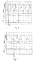
- Figures 4 and 5 show respective different graphs of different sets of voltage levels at a first bi-stable flip-flop of the circuitry shown in Figure 3 for different directions of longitudinal movement of a fishing line; and
- Figures 6 and 7 show respective different sets of voltage levels at a second bi-stable flip-flop of the circuitry shown in Figure 3 for such different directions of line movement.
-
- The fish-bite indicator shown in Figure 1 comprises a two-part synthetic plastics injection moulded
housing 10 having an external screw-threaded metal shank 12 extending downwardly from its underside. A seal is formed between thehousing 10 and the shank 12 by means of an O-ring 14 and a tightening nut 16 which urges the O-ring 14 tightly against thehousing 10 and inwardly against the shank 12. - The upper end of the
housing 10 is bifurcated, so that it has two generally upwardly extendingprongs 18, at the upper end of the left hand of which there is provided a lightemitting diode LED 20. - Inwardly
recessed ribs 22 are provided at the base of eachprong 18 to reinforce the housing in those regions. - A
slot 24 extends downwardly from the base of the bifurcation to expose acentral portion 25 of arotary part 26 contained within the housing. This central part is formed with. awaist 28, so that it has the form of a pulley-wheel. A generallycircular part 30 of thehousing 10 is provided underneath the bifurcation, slightly off-set from the longitudinal bisecting plane thereof, and is provided with a plurality ofapertures 32 to permit sound to travel more readily through thehousing 10 from a generally circularelectromagnetic buzzer diaphragm 34 positioned immediately inwardly of thediaphragm cover 30. Immediately above and slightly to the left of thediaphragm cover 30 there is an on-off/test switch 36 extending outwardly from thehousing 10. - Three
rotary knobs diaphragm cover 30, these knobs being, respectively, a volume control, pitch control and sensitivity control for the buzzer. - As shown in Figure 1a, the housing wall at each
knob aperture 44 through which extends ashaft 46 which is rigidly secured to the knob. The wall of thehousing 10 is raised at the annulus immediately surrounding theaperture 44. The underside of the knob is provided with askirt portion 48 which surrounds the raised annulus to form a seal between the knob and the surrounding wall. - Figure 2 shows the interior of that half of the two-
part housing 10 which is visible in Figure 1, with the other half of thehousing 10 removed to reveal interior components of the fish-bite indicator. That edge of the housing half which faces the other half of the housing is formed with a longitudinally extendingcentral rib 50. This engages a correspondingly formed longitudinally extending groove formed on the corresponding edge of the other housing part. Aninner wall 54 is formed in the housing and generally surrounds theslot 24 to form half of an enclosure which contains therotary part 26. - The rotary part has a tapering
spindle portion 56 extending in an intended horizontal direction away from thecentral portion 25. A second spindle portion 58 of therotary part 26 extends outwardly away from thecentral portion 25 in the opposite direction to that of thespindle portion 56. Respective recesses are formed in respective vertical parts of theinner wall 54 to provide rotary bearing means 60 and 62 respectively for the twospindle portions 56 and 58 of therotary part 26. - Four cylindrical blocks 64 (only two of which are visible in Figure 2) extend radially outwardly from the rotary axis of the
rotary part 26, spaced apart at 90° intervals therearound, and house respectivepermanent magnets 66. The length of each cylinder 64 andpermanent magnet 66 is such that, when the rotary part is rotated, the distal end of each magnet passes adjacent to abottom 68 of theinner wall 54. - The edges of the
inner wall 54 which face the other half of thehousing 10, are provided withformations 70 which interengage with corresponding formations formed on corresponding inner edges of the other half of the rotary part enclosure, to form a seal therewith. - The
slot 24 in each half of thehousing 10 extends to the upper face of thebottom 68 of the enclosure so that any water which finds its way into the enclosure can readily drain outwardly therefrom. - From the foregoing description, it will be appreciated that the housing, together with the
inner wall 54, defines a sealed interior. The latter contains a printedcircuit board 74 which is fixed to the interior of thehousing 10 and which includes tworeed switches rotary part 26, and both arranged generally parallel to that axis. - The
reed switches circuit board 74 immediately adjacent to thebottom 68 of theinner wall 54, within range of the magnetic fields of thepermanent magnets 66 as the latter pass by thebottom 68 when therotary part 26 rotates. - The printed
circuit board 74 is connected to theLED 20 vialeads 78, and power leads 80 extend from the printedcircuit board 74 to a 9 volt alkaline battery (not shown). - The on-off/
test switch 36, the buzzer having thebuzzer diaphragm 34, and each of the threecontrol knobs circuit board 74 to define circuitry shown in greater detail, and described hereinafter, with reference to Figure 3. - Figure 2 shows a bridging wall portion 84 of the housing which extends around an upper flange 86 of the shank 12. The flange 86 and the nut 16 therefore clamp tightly on to the bottom of the wall of the
housing 10 to fix the shank 12 rigidly to thehousing 10. - Internally screw-threaded horizontally extending
portions 88 are formed in the interior of the housing part, and apertures formed in the other housing part in registration with theportions 88 when the two housing parts are brought together, enable screws (not shown) to secure those two housing parts tightly together with therib 50 engaging the groove. - The manner in which the various parts of the indicator are connected together via the
circuit board 74 is shown in Figure 3. - The
reed switches flop 310. - In this particular circuitry, the
reed switch 76 is the one which is closed first upon movement of one of themagnets 66 as a result of longitudinal movement of a fishing line over therotary part 26 in a direction corresponding to pay-out of the line. - The _Q output from the flip-
flop 310 is connected to the set and reset inputs of a second bi-stable flip-flop 312. This flip-flop 312 is configured as a divide-by-to-counter. - A
trigger pulse generator 314 is connected to receive a signal from thereed switch 76 and to forward trigger pulses to the clock input of the flip-flop 312. Thesensitivity control 42 is connected to thetrigger pulse generator 314 so that the rate at which trigger pulses are issued therefrom in dependence upon a given frequency of pulses received from thereed switch 76 is dependent upon the setting of thesensitivity control 42. - The _Q output from the second flip-
flop 312 is fed back to the data input thereof. - Both the Q and _Q outputs from the bi-stable flip-
flop 312 are connected to abuzzer driver 316 which in turn is connected to drive abuzzer 318 provided with thediaphragm 34 shown in Figure 1. - The _Q output from the bi-stable flip-flop is connected via a
capacitor 320 to anLED driver 322 which in turn is connected to theLED 20. - The
volume control 38 andpitch control 40 are both connected to thebuzzer driver 316 in such a manner as to control the volume and pitch of the output from the buzzer, respectively. - The
power source 82, the on/off/test switch 36 and thebattery test circuit 104 are connected in series in that order, to theLED driver 322 to enable the detector to be switched on and off and also to enable the power source to be tested. - When the detector is installed for use, the fishing line of a fishing rod is passed over the
rotary part 26 so that longitudinal movement of the line will rotate that part. - In the event that a fish bite causes the fishing line to be paid out, successive movements of the
magnets 66 over the reed switches 76 and 77 cause closure of thereed switch 76 to precede closure of thereed switch 77 each time amagnet 66 passes over them. - The resulting voltage levels at the clock and data input respectively of the first flip-
flop 310 of the circuitry shown in Figure 3, are shown in Figure 4. From this, it will be seen that, at the instant the clock input is pulled high, the'data input is still low. As a result, the Q output of the flip-flop 310 goes low, and its complementary output _Q goes high. This occurs at the instant T1 shown in Figure 4, and at each successive responding instant in the cyclically changing wave forms. - Conversely, if the
rotary part 26 is rotated in the opposite sense, corresponding to a drop-back bite, then the clock input of the flip-flop 310 is pulled high while the data input is still high, because in this instant, it is thereed switch 77 which is closed before thereed switch 76 for a given passage of one of themagnets 66 over these reed switches. Such an instant is indicated at time T2 in Figure 5, and at each successive corresponding instant in the cyclically changing voltage levels. - At this instant, therefore, the Q output from the flip-
flop 310 goes high, and its complimentary output _Q goes low. - If the set and re-set inputs of the flip-
flop 312 are held high, as is the case for a normal bite where fishing line is paid out, with the _Q output of the flip-flop 310 being held high, then both of the outputs of the flip-flop 312 will also be held high, as shown in Figure 6. As a result, a single-tone intermittent audible output is issued from thebuzzer 318, its frequency being dependent upon the speed of movement of the line. Its volume and pitch will be dependent upon the setting of the volume and pitch controls 38 and 40 respectively. - In the event that the set and re-set inputs are held low, the Q and _Q outputs from the flip-
flop 312 will oscillate in anti-phase, at half the frequency of the clock pulses. As a result, a two-tone audible signal is issued from thebuzzer 318 at a frequency which is again dependent upon the speed of movement of the line. - As regards the
LED 20, this is illuminated continuously for a normal bite in which the fishing line is paid out, and intermittently for a drop-back bite. - Whilst the illustrated bite detector has been shown as a preferred embodiment of the present invention, it will be appreciated that the invention is not limited to this particular embodiment, and that very many variations and modifications will readily occur to a reader of ordinary skill in the art without taking the resulting detector outside the scope of the present invention. To give a few examples only, the reed switches 76 and 77 could be reversed, or the trigger pulse generator could be connected to the output from the
reed switch 77 instead of that of thereed switch 76. The buzzer driver could be connected only to the _Q output of the flip-flop 312 like the LED driver. The reed switches 76 and 77 could be arranged one beside the other on the printed circuit board, even so that they are generally co-linear, provided, with the illustrated arrangement of magnets, there is at least some component of the displacement of the respective centres of the reed switches in the directions of movement of themagnets 66 where they pass over those switches.
Claims (8)
- A fish-bite detector having at least one magnet (66) mounted to rotate about a given axis upon longitudinal movement of a fishing line which engages a part of the detector when the latter is in use, such as to change the magnetic field in a predetermined region of the detector in dependence upon such movement, and sensor means (76, 77) provided in the said predetermined region to produce a signal indicative of such movement, characterised in that the sensor means (76, 77) comprise two reed switches (76, 77) so arranged that they are generally parallel to the said given axis and so that one of those switches (76 or 77) is switched by the said magnet (66) passing it before the other one of those switches (77 or 76) is switched by the said magnet (66) passing it, whereby the detector can discriminate between different directions of longitudinal movement of the fishing line.
- A fish-bite detector according to claim 1, characterised in that one of the reed switches (76, 77) is connected to the clock input of a bi-stable flip-flop (310), and the other is connected to the data input thereof.
- A fish-bite detector according to claim 2, characterised in that the reed switch (76, 77) which is switched first when the fishing line moves in a direction corresponding to a paying out of the line, is connected to the clock input of the flip-flop (310).
- A fish-bite detector according to claim 2 or claim 3, characterised in that the Q and _Q outputs of the flip-flop (310) are connected to both the set and reset inputs of a second bi-stable flip-flop (312), the clock input of which is connected to receive an output from a trigger pulse generator (314) connected to one of the reed switches (76 or 77) to generate pulses in dependence upon closure of that reed switch (76 or 77), the _Q output of the second flip-flop (312) being fed back to the data input thereof.
- A fish-bite detector according to claim 4, characterised in that the trigger pulse generator (314) is connected to receive signals from that reed switch (76 or 77) which is connected to the clock input of the first-mentioned flip-flop (310).
- A fish-bite detector according to claim 4 or claim 5, characterised in that the _Q output of the second flip-flop (312) is connected to an LED driver (322) which in turn is connected to drive the LED (20).
- A fish-bite detector according to any one of claims 4 to 6, characterised in that Q and _Q outputs from the second flip-flop (312) are connected to a buzzer driver (316) which in turn is connected to a buzzer (318).
- A fish-bite detector according to claim 7, characterised in that the buzzer driver (316) is so constructed as to cause a first audio signal to be issued when the line moves in a longitudinal direction corresponding to a paying-out of the line, and a second audible signal when the line moves in the other longitudinal direction.
Applications Claiming Priority (2)
| Application Number | Priority Date | Filing Date | Title |
|---|---|---|---|
| GB9626824 | 1996-12-24 | ||
| GBGB9626824.8A GB9626824D0 (en) | 1996-12-24 | 1996-12-24 | Fish-bite detector |
Publications (2)
| Publication Number | Publication Date |
|---|---|
| EP0850562A1 EP0850562A1 (en) | 1998-07-01 |
| EP0850562B1 true EP0850562B1 (en) | 2003-10-08 |
Family
ID=10804983
Family Applications (1)
| Application Number | Title | Priority Date | Filing Date |
|---|---|---|---|
| EP19970310298 Expired - Lifetime EP0850562B1 (en) | 1996-12-24 | 1997-12-18 | Fish-bite detector |
Country Status (3)
| Country | Link |
|---|---|
| EP (1) | EP0850562B1 (en) |
| DE (1) | DE69725417T2 (en) |
| GB (1) | GB9626824D0 (en) |
Families Citing this family (8)
| Publication number | Priority date | Publication date | Assignee | Title |
|---|---|---|---|---|
| US6463691B1 (en) * | 1998-08-19 | 2002-10-15 | Michael R. Atkins | Magnetically actuated indicator device for a fishing rod, fishing rig incorporating the device, and method of using same |
| GB2348095B (en) * | 1999-03-26 | 2003-06-18 | Delkim Prod Ltd | Bite indicator |
| GB0005921D0 (en) | 2000-03-13 | 2000-05-03 | Fox Design Int | A fish-bite detector |
| SK16772001A3 (en) * | 2000-03-20 | 2002-04-04 | Marek Němec | A fish strike signaling device suspended from a fishing line |
| GB0710466D0 (en) | 2007-06-01 | 2007-07-11 | Fox Int Group Ltd | A fish-bite detector |
| GB2454734B (en) | 2007-11-19 | 2009-08-05 | Advanced Carp Equipment Ltd | Bite detector & method of detection |
| EP2147596A1 (en) | 2008-07-21 | 2010-01-27 | Fox International Group Limited | A fish-bite indicating device |
| GB2571700A (en) * | 2017-12-18 | 2019-09-11 | Wolf Holdings Ltd | A fishing line motion sensor |
Family Cites Families (4)
| Publication number | Priority date | Publication date | Assignee | Title |
|---|---|---|---|---|
| GB2086701B (en) * | 1980-10-23 | 1984-03-21 | Green Frank | Apparatus for use in fishing |
| GB9210262D0 (en) | 1992-05-13 | 1992-07-01 | Fox Design Int | Fish-bite indicators |
| GB2299252B (en) * | 1995-03-31 | 1999-04-21 | Darren Edward Elvins | Bite indicator |
| GB2313761A (en) * | 1996-06-06 | 1997-12-10 | Reynolds Hepburn Ltd | Fishing bite detector |
-
1996
- 1996-12-24 GB GBGB9626824.8A patent/GB9626824D0/en active Pending
-
1997
- 1997-12-18 EP EP19970310298 patent/EP0850562B1/en not_active Expired - Lifetime
- 1997-12-18 DE DE1997625417 patent/DE69725417T2/en not_active Expired - Lifetime
Also Published As
| Publication number | Publication date |
|---|---|
| DE69725417T2 (en) | 2004-05-19 |
| DE69725417D1 (en) | 2003-11-13 |
| GB9626824D0 (en) | 1997-02-12 |
| EP0850562A1 (en) | 1998-07-01 |
Similar Documents
| Publication | Publication Date | Title |
|---|---|---|
| US5321391A (en) | Fish-bite indicator | |
| DE69829411D1 (en) | ELECTRONIC SEARCH SYSTEM | |
| US4122437A (en) | Intrusion alarm control system | |
| FR2629536B1 (en) | MAGNETIC SENSOR BEARING WITH SELF-COMPENSATED DETECTION CIRCUIT | |
| EP0850562A1 (en) | Fish-bite detector | |
| EP0806673A3 (en) | Apparatus for detecting the speed of a rotating element | |
| EP1997372A2 (en) | A fish-bite detector | |
| EP0749687B1 (en) | A fish-bite indicator | |
| DE59915012D1 (en) | Inductive proximity switch with a preferably one-piece housing | |
| DE4316636A1 (en) | Speed sensor for vehicle road wheels - uses transistor circuit to derive speed signal from wheel rotation-dependent magnetic flux changes, using transducer forming rectangular pulses | |
| EP0720813B1 (en) | A fish-bite indicator | |
| GB1596260A (en) | Bite indicators | |
| EP1059029B1 (en) | Light indicator assembly | |
| EP1147704B1 (en) | A fish-bite detector | |
| US6035702A (en) | Drain plug sensor for watercraft | |
| GB2232863A (en) | A collapsible rod rest with bite indicator | |
| DE69907492D1 (en) | THREAD PROCESSING SYSTEM | |
| ES2135354A1 (en) | Improvements to disposable diapers | |
| JPH0311578B2 (en) | ||
| JPS6453114A (en) | Multiple rotation detecting device | |
| JPS605641Y2 (en) | non-contact pulse generator | |
| JPS5777984A (en) | Electronic clock | |
| KR0174193B1 (en) | Steering switch return device and method thereof | |
| SU1545972A1 (en) | Rig for checking sensors for monitoring liquid fertilizing | |
| JPS5743594A (en) | Controlling circuit of pulse motor |
Legal Events
| Date | Code | Title | Description |
|---|---|---|---|
| PUAI | Public reference made under article 153(3) epc to a published international application that has entered the european phase |
Free format text: ORIGINAL CODE: 0009012 |
|
| AK | Designated contracting states |
Kind code of ref document: A1 Designated state(s): BE DE FR GB IT NL |
|
| AX | Request for extension of the european patent |
Free format text: AL;LT;LV;MK;RO;SI |
|
| 17P | Request for examination filed |
Effective date: 19980928 |
|
| AKX | Designation fees paid |
Free format text: BE DE FR GB IT NL |
|
| RBV | Designated contracting states (corrected) |
Designated state(s): BE DE FR GB IT NL |
|
| 17Q | First examination report despatched |
Effective date: 20001128 |
|
| GRAH | Despatch of communication of intention to grant a patent |
Free format text: ORIGINAL CODE: EPIDOS IGRA |
|
| GRAS | Grant fee paid |
Free format text: ORIGINAL CODE: EPIDOSNIGR3 |
|
| GRAA | (expected) grant |
Free format text: ORIGINAL CODE: 0009210 |
|
| AK | Designated contracting states |
Kind code of ref document: B1 Designated state(s): BE DE FR GB IT NL |
|
| REG | Reference to a national code |
Ref country code: GB Ref legal event code: FG4D |
|
| REF | Corresponds to: |
Ref document number: 69725417 Country of ref document: DE Date of ref document: 20031113 Kind code of ref document: P |
|
| ET | Fr: translation filed | ||
| PLBE | No opposition filed within time limit |
Free format text: ORIGINAL CODE: 0009261 |
|
| STAA | Information on the status of an ep patent application or granted ep patent |
Free format text: STATUS: NO OPPOSITION FILED WITHIN TIME LIMIT |
|
| 26N | No opposition filed |
Effective date: 20040709 |
|
| PG25 | Lapsed in a contracting state [announced via postgrant information from national office to epo] |
Ref country code: IT Free format text: LAPSE BECAUSE OF NON-PAYMENT OF DUE FEES Effective date: 20091218 |
|
| PGRI | Patent reinstated in contracting state [announced from national office to epo] |
Ref country code: IT Effective date: 20110616 |
|
| REG | Reference to a national code |
Ref country code: NL Ref legal event code: U Designated state(s): GB Name of requester: FOX DESIGN INTERNATIONAL LIMITED, GB Effective date: 20120209 |
|
| REG | Reference to a national code |
Ref country code: GB Ref legal event code: 732E Free format text: REGISTERED BETWEEN 20120202 AND 20120208 |
|
| REG | Reference to a national code |
Ref country code: FR Ref legal event code: CL Name of requester: FOX INTERNATIONAL GROUP LIMITED, GB Effective date: 20120221 |
|
| REG | Reference to a national code |
Ref country code: DE Ref legal event code: R008 Ref document number: 69725417 Country of ref document: DE |
|
| REG | Reference to a national code |
Ref country code: DE Ref legal event code: R088 Ref document number: 69725417 Country of ref document: DE |
|
| REG | Reference to a national code |
Ref country code: DE Ref legal event code: R039 Ref document number: 69725417 Country of ref document: DE Effective date: 20120611 |
|
| REG | Reference to a national code |
Ref country code: DE Ref legal event code: R082 Ref document number: 69725417 Country of ref document: DE Representative=s name: LS-MP VON PUTTKAMER BERNGRUBER LOTH SPUHLER MU, DE Ref country code: DE Ref legal event code: R082 Ref document number: 69725417 Country of ref document: DE Representative=s name: VP-IP VON PUTTKAMER BERNGRUBER LOTH SPUHLER PA, DE Ref country code: DE Ref legal event code: R082 Ref document number: 69725417 Country of ref document: DE Representative=s name: VON PUTTKAMER BERNGRUBER, DE |
|
| REG | Reference to a national code |
Ref country code: DE Ref legal event code: R097 Ref document number: 69725417 Country of ref document: DE Ref country code: DE Ref legal event code: R040 Ref document number: 69725417 Country of ref document: DE |
|
| REG | Reference to a national code |
Ref country code: DE Ref legal event code: R040 Ref document number: 69725417 Country of ref document: DE Effective date: 20140904 |
|
| REG | Reference to a national code |
Ref country code: FR Ref legal event code: PLFP Year of fee payment: 19 |
|
| REG | Reference to a national code |
Ref country code: FR Ref legal event code: PLFP Year of fee payment: 20 |
|
| PGFP | Annual fee paid to national office [announced via postgrant information from national office to epo] |
Ref country code: GB Payment date: 20161223 Year of fee payment: 20 Ref country code: NL Payment date: 20161223 Year of fee payment: 20 |
|
| PGFP | Annual fee paid to national office [announced via postgrant information from national office to epo] |
Ref country code: BE Payment date: 20161222 Year of fee payment: 20 Ref country code: FR Payment date: 20161229 Year of fee payment: 20 |
|
| PGFP | Annual fee paid to national office [announced via postgrant information from national office to epo] |
Ref country code: DE Payment date: 20170228 Year of fee payment: 20 |
|
| PGFP | Annual fee paid to national office [announced via postgrant information from national office to epo] |
Ref country code: IT Payment date: 20161227 Year of fee payment: 20 |
|
| REG | Reference to a national code |
Ref country code: DE Ref legal event code: R071 Ref document number: 69725417 Country of ref document: DE |
|
| REG | Reference to a national code |
Ref country code: NL Ref legal event code: MK Effective date: 20171217 |
|
| REG | Reference to a national code |
Ref country code: GB Ref legal event code: PE20 Expiry date: 20171217 |
|
| REG | Reference to a national code |
Ref country code: BE Ref legal event code: MK Effective date: 20171218 |
|
| PG25 | Lapsed in a contracting state [announced via postgrant information from national office to epo] |
Ref country code: GB Free format text: LAPSE BECAUSE OF EXPIRATION OF PROTECTION Effective date: 20171217 |
|
| REG | Reference to a national code |
Ref country code: FR Ref legal event code: CA Effective date: 20180205 |