EP0849892A2 - Signal multiplexing method and transmitting/receiving apparatus therefor - Google Patents
Signal multiplexing method and transmitting/receiving apparatus therefor Download PDFInfo
- Publication number
- EP0849892A2 EP0849892A2 EP97310206A EP97310206A EP0849892A2 EP 0849892 A2 EP0849892 A2 EP 0849892A2 EP 97310206 A EP97310206 A EP 97310206A EP 97310206 A EP97310206 A EP 97310206A EP 0849892 A2 EP0849892 A2 EP 0849892A2
- Authority
- EP
- European Patent Office
- Prior art keywords
- reception
- antenna
- transmission
- signal transmission
- directivity
- Prior art date
- Legal status (The legal status is an assumption and is not a legal conclusion. Google has not performed a legal analysis and makes no representation as to the accuracy of the status listed.)
- Granted
Links
Images


Classifications
-
- H—ELECTRICITY
- H01—ELECTRIC ELEMENTS
- H01Q—ANTENNAS, i.e. RADIO AERIALS
- H01Q3/00—Arrangements for changing or varying the orientation or the shape of the directional pattern of the waves radiated from an antenna or antenna system
- H01Q3/02—Arrangements for changing or varying the orientation or the shape of the directional pattern of the waves radiated from an antenna or antenna system using mechanical movement of antenna or antenna system as a whole
-
- H—ELECTRICITY
- H01—ELECTRIC ELEMENTS
- H01Q—ANTENNAS, i.e. RADIO AERIALS
- H01Q25/00—Antennas or antenna systems providing at least two radiating patterns
-
- H—ELECTRICITY
- H01—ELECTRIC ELEMENTS
- H01Q—ANTENNAS, i.e. RADIO AERIALS
- H01Q3/00—Arrangements for changing or varying the orientation or the shape of the directional pattern of the waves radiated from an antenna or antenna system
- H01Q3/26—Arrangements for changing or varying the orientation or the shape of the directional pattern of the waves radiated from an antenna or antenna system varying the relative phase or relative amplitude of energisation between two or more active radiating elements; varying the distribution of energy across a radiating aperture
- H01Q3/2605—Array of radiating elements provided with a feedback control over the element weights, e.g. adaptive arrays
-
- H—ELECTRICITY
- H04—ELECTRIC COMMUNICATION TECHNIQUE
- H04B—TRANSMISSION
- H04B7/00—Radio transmission systems, i.e. using radiation field
- H04B7/24—Radio transmission systems, i.e. using radiation field for communication between two or more posts
- H04B7/26—Radio transmission systems, i.e. using radiation field for communication between two or more posts at least one of which is mobile
- H04B7/2643—Radio transmission systems, i.e. using radiation field for communication between two or more posts at least one of which is mobile using time-division multiple access [TDMA]
- H04B7/2646—Radio transmission systems, i.e. using radiation field for communication between two or more posts at least one of which is mobile using time-division multiple access [TDMA] for broadband transmission
-
- H—ELECTRICITY
- H04—ELECTRIC COMMUNICATION TECHNIQUE
- H04B—TRANSMISSION
- H04B7/00—Radio transmission systems, i.e. using radiation field
- H04B7/02—Diversity systems; Multi-antenna system, i.e. transmission or reception using multiple antennas
- H04B7/04—Diversity systems; Multi-antenna system, i.e. transmission or reception using multiple antennas using two or more spaced independent antennas
- H04B7/0408—Diversity systems; Multi-antenna system, i.e. transmission or reception using multiple antennas using two or more spaced independent antennas using two or more beams, i.e. beam diversity
Definitions
- This invention relates to a signal transmitting/receiving method and apparatus, applied with advantage to a portable telephone system, a cordless telephone system and an inside radio communication system.
- FDMA frequency-division multiplexing access
- TDMA time-division multiplexing access
- CDMA code-division multiplexing access
- the FDMA system is a communication method in which each modulation wave modulates a separate sub-carrier wave having its frequency separated a certain width. That is, in FDMA, signals occupying non-overlapping frequency ranges are summed together. By using different frequency bands, two or more separate signals can be transmitted by one and the same transmission channel. A desired signal can be taken out by a filter. This multiplexing system is not in need of synchronization.
- the TDMA is a communication system in which a transmission device uses the common channel intermittently and a channel is established in a specified receiver device by an automatic distribution function. Specifically, signals compressed to high-speed burst signals are arranged in specified time slots in such a manner as to evade temporal overlap. The desired signal is reproduced on extracting the time slots. The system is synchronized because timing reference is required.
- the CDMA is a multiplexing communication method employing insignia (identifiable properties or codes) proper to the signals. Demultiplexing is by utilizing code correlation characteristics with previously known reference signals. The signals handled with this system are usually digital signals.
- the band In the conventional practice, if it is attempted to transmit the information simultaneously within one and the same band from the same site to some other same site, the band needs to be enlarged as compared to the bandwidth of the original information. Thus, if the bandwidth is limited, the number of channels that can be accommodated is restricted.
- the present invention provides a signal transmission/reception device including a transmitting antenna having N different directivities, N transmission means associated with the directivities of the transmission antenna, a receiving antenna having N directivities associated with the respective directivities of the transmitting antenna and N reception means associated with the directivities of the receiving antenna, wherein N different information items transmitted from the N transmission means via N different paths associated with the N directivities of the transmitting antenna are received via receiving antennas with the N directivities as multiplexed signals.
- signal transmission/reception device of the present invention signal multiplexing can be realized with the same frequency without enlarging the information bandwidth for increasing the frequency utilization efficiency while realizing a large-capacity radio communication system.
- the present invention provides a signal transmission/reception method wherein N different information items are transmitted via N different paths associated with N directivities of a transmission antenna and wherein the transmitted information is received as multiplexed signal by a receiving antenna having N directivities associated with N directivities of the transmission antenna.
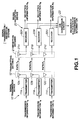
- Fig.1 is a block diagram showing a first embodiment of the signal transmission/reception device and method according to the present invention.
- Fig.2 illustrates the principle of the operation of the first embodiment of the signal transmission/reception system.
- Fig.3 illustrates, similarly to Fig.2, the principle of the operation of the first embodiment of the signal transmission/reception system.
- Fig.4 is a schematic view showing a controller for mechanically rotating a receiving side antenna in the first embodiment.
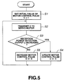
- Fig.5 is a flowchart for illustrating the operation of the controller shown in Fig.4.
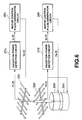
- Fig.6 is a schematic view of a controller for coping with two receiving side antennas.
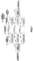
- Fig.7 is a block diagram showing a first embodiment of the signal transmission/reception device and method according to the present invention.
- Fig.8 is a block diagram showing a third embodiment of the signal transmission/reception device and method according to the present invention.
- Fig.9 is a graph showing directivity characteristics of a receiving array antenna employed in the third embodiment.
- Figs.10A and 10B illustrate a typical sequence of setting the array antenna directivity in the third embodiment.
- Figs.11A, 11B and 11C illustrate another typical sequence of setting the array antenna directivity in the third embodiment.
- the first embodiment directed to a signal transmission/reception system for transmitting three different transmission information items from a given site to some other site by the same frequency, at the same time point and within one and the same band, is now explained.
- this signal transmission/reception system 1 includes a signal transmitting device 10 for multiplexed transmission of three different items of the transmission information T A , T B and T C from transmitters11 A , 11 B and 11 C over a transmission antenna 12 through three different paths P A , P B and P C .
- the signal transmission/reception system also includes a signal reception device 20 for receiving the three multiplexed different items of the information transmitted through the three different paths P A , P B and P C by receivers 22 A , 22 B and 22 C using a reception antenna 21 for producing three different items of the received information R A , R B and R C .
- the three items of the transmitted information T A , T B and T C are transmitted by electrical waves of the same frequency. If the transmission route is the same, these electrical waves interfere with one another, so that it is difficult to realize transmission with high signal quality.
- the multiplexed transmission by the above-mentioned FDMA, TDMA and CDMA is in need of a bandwidth broader than the original information bandwidth.
- the present signal reception system uses a multiplexing method which may be termed a path-division multiplexing method in which paths are independently different and different items of the information are carried on electric waves passing through the different paths.
- a transmission antenna unit 12 of the signal transmission device 10 has three directive antennas 12 A , 12 B and 12 C and hence has three different directivities.
- a receiving antenna unit 21 of the signal transmission device 20 also has three directive antennas 21 A , 21 B and 21 C and hence has three different directivities.
- the transmission side directive antennas 12 A , 12 B and 12 C have directivities set in meeting with directive paths of the associated receiving directive antennas 21 A , 21 B and 21 C , respectively.
- the receiving directive antennas 21 A , 21 B and 21 C suppress the intensity of the signals passing through the different paths to a sufficiently low level.
- the principle of the path-division multiplexing method is now explained.
- the electric waves arriving at the receiving antenna pass through plural paths, instead of through a sole path.
- a receiving side non-directive antenna 32 receives a signal which is composed of three signals transmitted through three paths P A , P B and P C independent from a transmitting side non-directive antenna 31, these three signals being overlapped together.
- one set each of directive antennas are allocated at a transmission point 33 and at a reception point 34 to each of the three independent paths P A , P B and P C . That is, a set of directive antennas is allocated to the path P A , while another set of directive antennas is allocated to the path P B and a further set of directive antennas is allocated to the path P C for transmitting respective independent information items. This secures an independent communication path for the antenna on the same site using the same frequency.
- one set each of directive antennas are allocated at the signal transmission device 10 and at the signal reception device 20 to each of the three independent paths P A , P B and P C . That is, the directive antennas 12 A and 21 A are allocated to the path P A , while the directive antennas 12 B and 21 B are allocated to the path P B and the directive antennas 12 C and 21 C are allocated to the path P C , for having different information items carried by the electric waves passing through three different paths for multiplex transmission of the three different information items using the same frequency.
- the communication capacity can be increased without enlarging the frequency domain under suppression of interference. This increases the frequency utilization efficiency in proportion to the number of paths.
- reception directivities of the transmission side directive antennas 12 A , 12 B and 12 C and those of the transmission side directive antennas 12 A , 12 B and 12 C need to be set appropriately in the directions of the paths P A , P B and P C , respectively.
- a sequence of setting the directivities at the communication start time is required, while haphazard directivity setting cannot lead to successful communications.
- the transmitting side If an antenna of fixed directivity, such as Yagi antenna, it is possible for the transmitting side to rotate an element in search of a proper direction of reception by the receiving side, which then is non-directive.
- the direction of the transmission antenna directivity can be set first. It is not critical which side antenna directivity is to be set first.
- the receiving side directive antennas 21 A , 21 B or 21 C can be rotated mechanically by a servo motor.
- Fig.4 shows a control device for mechanically rotating a directive antenna 35 by a sole servo motor 36.
- a motor control pulse generating circuit 38 generates a motor control pulse C(t), based on the reception power detecting output y(t), for supplying the generated pulse to the servo motor 36, which then is responsive to the motor control pulse C(t) to rotate the antenna 35 at a pre-set pitch towards left or right.
- the motor control pulse generating circuit 38 constitutes a control circuit and controls the operation of the control device in accordance with the flowchart of Fig.5.
- the motor control pulse is transmitted to the servo motor 36.
- the servo motor 36 then rotates the antenna 35 clockwise by one pitch. It is noted that clockwise rotation of the antenna occurs when the motor control pulse C(t) is +1, while counterclockwise rotation thereof occurs when the motor control pulse C(t) is -1.
- the motor control pulse generating circuit 38 judges whether or not the reception power detecting output y(t) as detected by the reception power detecting circuit 37 has been increased. If the reception power detecting output y(t) is found to have been increased, the motor control pulse generating circuit 38 at step S4 updates the motor control pulse C. On the other hand, if the reception power detecting output y(t) cannot be found to have been increased, the motor control pulse generating circuit 38 at step S5 increments the motor control pulse C by +1, for example, for controlling the rotation of the servo motor 36 to control the rotation of the servo motor 36 to rotate the antenna 35 by one pitch. The processing as from step S2 to step S5 then is repeated.
- reception power detecting circuit 37A or a reception power detecting circuit 37B and a motor control pulse generating circuit 38A or a motor control pulse generating circuit 38B are provided for each set of the antenna 35A or 35B and the servo motor 36A or 36B, as shown for example in Fig.6.
- the directivity antennas of the transmission antenna unit 12 are rotated under control by the control unit shown in Fig.4 or 6 for maximizing the C/N (carrier to noise) ratio of each receiver.
- Each of the three receivers 22 A , 22 B and 22 C has a C/N measurement circuit.
- the results of comparison are compared by a C/N comparator circuit 23.
- the signal transmission device 10 allocates the information in the order of the decreasing value of priority to the transmitters 11 A , 11 B and 11 C in the order of the decreasing magnitude of the C/N ratio of the paths P A , P B and P C .
- This second embodiment is directed to a signal transmission/reception system for transmitting three different parallel-converted information items from a given point to another given point with the same frequency, at the same time point and within the same area.
- this signal transmission/reception system 40 includes a signal transmission/reception device 45 for converting a given serially transmitted information item To by a serial/parallel converter 46 into three parallel signals for path-division multiplexing transmission from three transmitters 47 A , 47 B and 47 C over three different paths P A , P B , P C , using the directivity antennas 48 A , 48 B and 48 C of the transmitting antenna unit 48 C , respectively.
- the signal transmission/reception system 40 also includes a signal receiving unit 50 for receiving the three parallel transmitted information items, sent over the three different paths P A , P B , P C by path-division multiplex transmission by receivers 52 A , 52 B and 52 C using directive antennas 51 A , 51 B and 51 C of the reception antenna unit 51 by for converting the received information items by a parallel/serial converter 53 into a sole serial reception information item.
- a signal receiving unit 50 for receiving the three parallel transmitted information items, sent over the three different paths P A , P B , P C by path-division multiplex transmission by receivers 52 A , 52 B and 52 C using directive antennas 51 A , 51 B and 51 C of the reception antenna unit 51 by for converting the received information items by a parallel/serial converter 53 into a sole serial reception information item.
- the transmission directive antennas 48 A , 48 B and 48 C of the signal transmission/reception device 45 have directivities set in meeting with the directive paths of the reception detective antennas 51 A , 51 B and 51 C of the associated signal receiving device 50.
- the receiving side directive antennas 51 A , 51 B and 51 C suppress the intensity of the signals passed through the different paths to a sufficiently small level.
- a sole transmission information item To is first converted into three parallel information items which are then sent by path-division multiplexing transmission over three independent paths P A , P B and P C .
- the receiving side then converts the three parallel information items into a sole serial information item.
- one-third bandwidth suffices for transmitting the information for the same information rate, while the information volume can be trebled for the same bandwidth. That is, with the present 40, the frequency utilization efficiency can be increased in proportion to the number of paths.
- these receiving side directive antennas 51 A , 51 B and 51 C can also be mechanically rotated by a servo motor, as explained with reference to Figs.4 to 6.
- the directivity of the transmission antenna unit transmission antenna unit 48 can be set for maximizing the C/N ratio of each receiver by rotating the directive antennas of the transmission antenna unit transmission antenna unit 48 under control by the control unit analog signals shown in Figs.4 and 6.
- This third embodiment is directed to a signal transmission/reception system for transmitting two different information items with the same frequency at the same time point in one and the same area from a given point to another given point with the use of an array antenna in each of the transmission and reception sides.
- the signal transmission/reception system 80 includes a signal transmission device signal transmission device 62 for path-division multiplex transmission of two different items of transmission information T A and T B from two transmitters 63 A , 63 B using a transmission array antenna 64 over two different paths P A and P B , and a signal reception device 70 for receiving the two different items of transmission information T A and T B by path-division multiplex transmission over the two different paths P A and P B by receivers 76 A , 76 B using a receiving array antenna 71 for producing two different items of the received items of information R A and RB.
- the array antenna means such an antenna comprised of an array of plural sensor array elements and having the function of adaptively changing the directivity to the prevailing electric wave environment in which the antenna is put by adjusting gain coefficients afforded to each sensor array element.
- a transmission array antenna 64 includes coefficient multipliers 66 1 , 66 2 , ..., 66n, for multiplying the transmission information T A from the transmitter 63 A with coefficients G A1 G A2 , ..., G An , and coefficient multipliers 67 1 , 67 2 , ..., 67n, for multiplying the transmission information T B from the transmitter 63 B with coefficients G B1 , G B2 , ..., G Bn .
- the transmission array antenna 64 also includes adders 68 1 , 68 2 , ..., 68 n for summing together the results of multiplication obtained on multiplication with the coefficients by the coefficient multipliers 67 1 , 66 2 , 67 2 , 66 n and 67 n .
- the transmission array antenna 64 also includes sensor array elements 69 1 , 69 2 , ..., 69 n for multiplying the sum outputs of these adders 68 1 , 68 2 , ..., 68 n with the coefficients G A1 , G A2 , ..., G An to output the resulting outputs (one outputs) via path P A to the reception array antenna 71 as electric waves, and for multiplying the sum outputs of these adders 68 1 , 68 2 , ..., 68n with the coefficients G B1 , G B2 , ..., G Bn to output the resulting outputs (other outputs) via path P B to the reception array antenna 71 as electric waves.
- the reception array antenna 71 includes sensor array elements 72 1 , 72 2 , ..., 72 n for converting the transmission information T A and the transmission information T B transmitted via paths P B and P A and the electric waves concerning the information T A and T B into information signals, and coefficient multipliers 73 1 , 73 2 , ..., 73 n for multiplying n parallel outputs from the sensor array elements 72 1 , 72 2 , ..., 72 n with coefficients G A1 G A2 , ..., G An .
- the reception array antenna 71 also includes coefficient multipliers 73 1 , 73 2 , ..., 73 n for multiplying n parallel outputs with coefficients G B1 , G B2 , ..., G Bn and an adder 75 A for synthesizing outputs of the coefficient multipliers 73 1 , 73 2 , ..., 73 n and an adder 75 B for synthesizing outputs of the coefficient multipliers 74 1 , 74 2 , ..., 74 n .
- the array antenna 71 for reception adjusts the coefficients G A1 , G A2 , ..., G An so as to give directivity indicated by a solid line for the path P A .
- the array antenna 71 for reception also adjusts the coefficients G B1 , G B2 , ..., G Bn so as to give directivity indicated by a solid line for the path P B .
- the solid-line directivity for the path P A has a null point for the path P B
- the broken-line directivity for the path P B has a null point for the path P A . That is, the lobe need not be sharp for the opposite side paths since the directivity need only be sufficient to attenuate the signals of the opposite side paths to a sufficient amplitude.
- the above coefficients G A1 , G A2 , ... G An are adjusted so that the array antenna for reception 71 will have directivity as shown by a solid line for the path P A .
- the above coefficients G B1 , G B2 , ..., G Bn are adjusted so that the array antenna for reception 71 will have directivity as indicated by a broken line for the path P A .
- the solid-line directivity for the path P A has a null point for the path P B
- the broken-line directivity for the path P B has a null point for the path P A . That is, the lobe need not be sharp for the opposite side paths since the directivity need only be sufficient to attenuate the signals of the opposite side paths to a sufficient amplitude.
- the reception information R A is obtained from the output voltage y A (t)
- the reception information R B is obtained from the output voltage y B (t).
- the above coefficients are set for maximizing the C/N ratio of the signal of the required path and for minimizing the BER.
- the directivity is set for enlarging the gain in the arrival direction of the desired waves and for diminishing the gain in the direction of the arriving waves passing through a different path will be smaller as the above-mentioned null point.
- a non-directive pattern can be produced using only a sole sensor array element.
- the sequence of operations for setting the transmission directivity and reception directivity appropriately for respective paths is carried put beginning from the directivity of the reception antenna because of the excessively large degree of freedom of the directive pattern. The reason is that it is not clear at the outset which pattern should be set in the transmission pattern, that is in which direction transmission should occur strongly and in which direction transmission should cease to occur.
- a non-directive pattern can be produced using only a sole sensor array element. It is possible to transmit signals non-directively and to select several suitable directivities on the receiving side. Then it is sufficient if the directivity of the transmitting antenna is set properly for sending out the separate information in the directions of the respective paths.
- Fig.10 an illustrative example of setting the directivity of the transmission side and the reception side sets of the array antennas is explained. This method sets the transmission and reception antenna pairs so that these antenna pairs will have opposite directivities.
- the directivity of the reception antenna is set.
- suitable coefficients G A1 , G A2 , ⁇ , G An , G B1 , G B2 , ..., G Bn are used in the coefficient multipliers 66 1 , 66 2 , ..., 66 n , 67 1 , 67 2 , ..., 67 n and a sole sensor array element 69 is used.
- the sensor array element 72 n accords suitable coefficients G A1 , G A2 , ..., G An by the coefficient multipliers 73 1 , 73 2 , ..., 73 n for matching the directivity to the optimum path P A of the paths P B and P A .
- the sensor array element 72 n accords suitable coefficients G B1 , G B2 , ..., G Bn by the coefficient multipliers 74 1 , 74 2 , ..., 74 n for matching the directivity to the optimum path P B of the paths P B and P A . This completes setting of the directivity of the reception antenna.
- the directivity of the transmission antenna is then set as shown in Fig.10B.
- the directivity of the reception antenna is that previously set by the above sequence of operations.
- the pre-set coefficients are accorded to the transmission antenna as coefficients and a training sequence is sent in order to find the C/N ratio of the reception output at this time.
- the error information such as BER or the C/N ratio on the receiving side needs to be fed back to the transmission side.
- LMS least mean square error
- CPM constrained power minimization
- CMA constant modulus algorithm
- the LMS method is used, that is, a training sequence is sent as described above in order to find the C/N ratio of the reception output at this time.
- Fig.ll shows an instance in which the transmitting frequency is equal to the receiving frequency and transmission and reception occur alternately.
- the transmitting side TX is set to be non-directive and the directivity of the receiving side RX has its directivity set by controlling its coefficients, as shown in Fig.llA.
- the transmission and reception are then interchanged, as shown in Fig.llB.
- the coefficients used for reception are used as coefficients for the transmitting side TX. Since the antenna used so far on the transmitting side is now changed over to the receiving side, its coefficients are found.
- the transmission and reception are then again interchanged, as shown in Fig.11C, and the coefficients are used for the transmission side.
- the transmitting information T A and the reception information T B entering the transmitters 63 A and 63 B may be the information converted in parallel during the preceding stage.
- the transmitting information T A and the reception information T B are inherently the same serial information and are converted by the preceding stage serial/parallel converter into two parallel information items, namely the transmitting information T A and the reception information T B , which are transmitted by the transmission array antenna transmission array antenna 64 to the signal reception device 70 so as to be passed through the paths P A and P B .
- the signal reception device 70 synthesizes the reception information R A and the reception information R B obtained by the receivers 76 A and 76 B by a parallel/serial converter of the succeeding stage to obtain a sole reception information item.
- the frequency utilization efficiency can be improved in proportion to the number of paths, as in the signal transmission/reception system 40 described above.
- the two receivers 76 A and 76 B each have a C/N ratio measurement circuit. The results of comparison by these circuits are compared by the C/N comparator circuit.
- the signal transmission device signal transmission device 62 allocates the information of higher order in transmission sequence to the transmitters 63 A and 63b in the order of decreasing C/N ratio.
Landscapes
- Engineering & Computer Science (AREA)
- Computer Networks & Wireless Communication (AREA)
- Signal Processing (AREA)
- Radio Transmission System (AREA)
- Variable-Direction Aerials And Aerial Arrays (AREA)
- Time-Division Multiplex Systems (AREA)
- Transceivers (AREA)
- Mobile Radio Communication Systems (AREA)
Abstract
Description
Claims (21)
- A signal transmission/reception device comprising:a transmitting antenna having N directivities;N transmission means associated with the directivities of the transmission antenna;a receiving antenna having N directivities associated with the respective directivities of the transmitting antenna; andN reception means associated with the directivities of the receiving antenna; whereinN different information items transmitted from the N transmission means via N different paths associated with the N directivities of the transmitting antenna are received via receiving antennas with the N directivities as multiplexed signals.
- The signal transmission/reception device as claimed in claim 1, wherein at least said reception antenna is mechanically rotated to follow up with changes in the paths or arriving direction of the electric waves.
- The signal transmission/reception device as claimed in claim 1 or 2, wherein said N transmitting means transmit the N items of the parallel information from serial/parallel conversion means splitting the sole information item into plural stages from said transmitting antenna over N different paths as electric waves and wherein said N reception means receive the electric waves from said N different paths over said reception antenna and subsequently revert the received electric waves into a sole serial information item by parallel/serial conversion means.
- The signal transmission/reception device as claimed in claim 3, wherein at least said reception antenna is mechanically rotated to follow up with changes in the paths or arriving direction of the electric waves.
- The signal transmission/reception device as claimed in claim 2, 3 or 4, wherein transmission directivity when the C/N ratio of the reception means becomes maximum on rotating the transmitting antenna after setting the directivity of the reception antenna is set.
- The signal transmission/reception device as claimed in claim 3, wherein transmission directivity when the C/N ratio of the reception means becomes maximum on rotating the transmitting antenna after setting the directivity of the reception antenna is set.
- The signal transmission/reception device as claimed in any one of the preceding claims, wherein each transmission means has C/N measurement means, measured C/N values are compared by C/N comparator means and wherein the transmitting side allocates the information of higher priority in the order of decreasing C/N value of the paths.
- The signal transmission/reception device as claimed in any one of the preceding claims wherein a set of array antennas which follow up with changes in the paths or in the arriving direction of the electric waves are used as said transmitting antenna or receiving antenna.
- The signal transmission/reception device as claimed in claim 8, wherein said N transmitting means transmit the N items of the parallel information from serial/parallel conversion means splitting the sole information item into plural stages from said transmitting antenna over N different paths as electric waves and wherein said N reception means receive the electric waves from said N different paths over said reception antenna and subsequently revert the received electric waves into a sole serial information item by parallel/serial conversion means.
- The signal transmission/reception device as claimed in claim 8, wherein a training sequence sent from said transmitting antenna as non-directive antenna is received, the coefficients on the receiving antenna side are set and reception directivity is subsequently set.
- The signal transmission/reception device as claimed in claim 9, wherein a training sequence sent from said transmitting antenna as non-directive antenna is received, the coefficients on the receiving antenna side are set and reception directivity is subsequently set.
- The signal transmission/reception device as claimed in claim 8, 9 10 or 11, wherein after setting the directivity of the reception antenna, the directivity of said transmitting antenna is scanned and such transmission directivity is accorded which will maximize the C/N ratio of the reception means.
- The signal transmission/reception device as claimed in claim 9, 10, 11 or 12, wherein after setting the directivity of the reception antenna, the directivity of said transmitting antenna is scanned and such transmission directivity is accorded which will maximize the C/N ratio of the reception means.
- The signal transmission/reception device as claimed in any one of claims 8 to 13, wherein each transmission means has C/N measurement means, measured C/N values are compared by C/N comparator means and wherein the transmitting side allocates the information of higher priority in the order of decreasing C/N value of the paths.
- The signal transmission/reception device as claimed in claim 8, wherein directivity of said reception antenna is first set and transmission directivity is then set using coefficients of said reception antenna.
- The signal transmission/reception device as claimed in claim 9, wherein directivity of said reception antenna is first set and transmission directivity is then set using coefficients of said reception antenna.
- A signal transmission/reception method wherein N different information items are transmitted via N different paths associated with N directivities of a transmission antenna and wherein the transmitted information is received as multiplexed signal by a receiving antenna having N directivities associated with N directivities of said transmission antenna.
- The signal transmission/reception method as claimed in claim 17 wherein at least said reception antenna is mechanically rotated to follow up with changes in the paths or arriving direction of the electric waves.
- The signal transmission/reception method as claimed in claim 17 or 18, wherein the N different information items are N parallel information items obtained on dividing a sole information item into N stages which are received by said receiving antenna as multiplexed signals and subsequently reverted into a sole serial information item.
- The signal transmission/reception method as claimed in claim 17, 18 or 19, wherein a set of array antennas which follow up with changes in the paths or in the arriving direction of the electric waves are used as said transmitting antenna or receiving antenna.
- The signal transmission/reception method as claimed in claim 20 wherein the N different information items are N parallel information items obtained on dividing a sole information item into N stages which are received by said receiving antenna as multiplexed signals and subsequently reverted into a sole serial information item.
Priority Applications (1)
| Application Number | Priority Date | Filing Date | Title |
|---|---|---|---|
| EP10009947A EP2256946A3 (en) | 1996-12-19 | 1997-12-15 | Signal multiplexing method and transmitting/receiving apparatus therefor |
Applications Claiming Priority (4)
| Application Number | Priority Date | Filing Date | Title |
|---|---|---|---|
| JP340154/96 | 1996-12-19 | ||
| JP34015496 | 1996-12-19 | ||
| JP34015496A JP3709639B2 (en) | 1996-12-19 | 1996-12-19 | Signal transmitting / receiving apparatus and method |
| US08/987,103 US6173190B1 (en) | 1996-12-19 | 1997-12-08 | Signal receiving apparatus and method |
Related Child Applications (1)
| Application Number | Title | Priority Date | Filing Date |
|---|---|---|---|
| EP10009947.2 Division-Into | 2010-09-20 |
Publications (3)
| Publication Number | Publication Date |
|---|---|
| EP0849892A2 true EP0849892A2 (en) | 1998-06-24 |
| EP0849892A3 EP0849892A3 (en) | 2000-06-07 |
| EP0849892B1 EP0849892B1 (en) | 2013-06-19 |
Family
ID=42985335
Family Applications (2)
| Application Number | Title | Priority Date | Filing Date |
|---|---|---|---|
| EP10009947A Withdrawn EP2256946A3 (en) | 1996-12-19 | 1997-12-15 | Signal multiplexing method and transmitting/receiving apparatus therefor |
| EP97310206.4A Expired - Lifetime EP0849892B1 (en) | 1996-12-19 | 1997-12-15 | Signal multiplexing method and transmitting/receiving apparatus therefor |
Family Applications Before (1)
| Application Number | Title | Priority Date | Filing Date |
|---|---|---|---|
| EP10009947A Withdrawn EP2256946A3 (en) | 1996-12-19 | 1997-12-15 | Signal multiplexing method and transmitting/receiving apparatus therefor |
Country Status (3)
| Country | Link |
|---|---|
| US (1) | US6173190B1 (en) |
| EP (2) | EP2256946A3 (en) |
| JP (1) | JP3709639B2 (en) |
Cited By (1)
| Publication number | Priority date | Publication date | Assignee | Title |
|---|---|---|---|---|
| WO2009000964A1 (en) | 2007-06-28 | 2008-12-31 | Elektrobit Wireless Communications Oy | Apparatus of multi-antenna telecommunication system |
Families Citing this family (28)
| Publication number | Priority date | Publication date | Assignee | Title |
|---|---|---|---|---|
| SE514624C2 (en) * | 1998-12-22 | 2001-03-26 | Ericsson Telefon Ab L M | Method and arrangement for establishing a link between two fixed nodes in a mobile radio system using adaptive antennas and a reflective body |
| US6338103B1 (en) * | 1999-03-24 | 2002-01-08 | International Business Machines Corporation | System for high-speed data transfer using a sequence of overlapped global pointer signals for generating corresponding sequence of non-overlapped local pointer signals |
| US6757553B1 (en) * | 1999-10-14 | 2004-06-29 | Qualcomm Incorporated | Base station beam sweeping method and apparatus using multiple rotating antennas |
| CN1440599A (en) * | 2000-04-10 | 2003-09-03 | 威罗门飞行公司 | Communications system |
| JP2001320756A (en) * | 2000-05-11 | 2001-11-16 | Nec Saitama Ltd | Overload detection circuit for incoming line and base station device |
| US7162273B1 (en) * | 2000-11-10 | 2007-01-09 | Airgain, Inc. | Dynamically optimized smart antenna system |
| IL155808A0 (en) * | 2000-11-10 | 2003-12-23 | Am Group Corp | Direction-agile antenna system for wireless communications |
| US20020073437A1 (en) * | 2000-12-12 | 2002-06-13 | Hughes Electronics Corporation | Television distribution system using multiple links |
| US7181162B2 (en) * | 2000-12-12 | 2007-02-20 | The Directv Group, Inc. | Communication system using multiple link terminals |
| US6952580B2 (en) * | 2000-12-12 | 2005-10-04 | The Directv Group, Inc. | Multiple link internet protocol mobile communications system and method therefor |
| US7103317B2 (en) * | 2000-12-12 | 2006-09-05 | The Directv Group, Inc. | Communication system using multiple link terminals for aircraft |
| US7187949B2 (en) * | 2001-01-19 | 2007-03-06 | The Directv Group, Inc. | Multiple basestation communication system having adaptive antennas |
| US8396513B2 (en) * | 2001-01-19 | 2013-03-12 | The Directv Group, Inc. | Communication system for mobile users using adaptive antenna |
| US7809403B2 (en) * | 2001-01-19 | 2010-10-05 | The Directv Group, Inc. | Stratospheric platforms communication system using adaptive antennas |
| US7068616B2 (en) * | 2001-02-05 | 2006-06-27 | The Directv Group, Inc. | Multiple dynamic connectivity for satellite communications systems |
| WO2005101687A2 (en) * | 2004-04-13 | 2005-10-27 | Airgain, Inc. | Direction-agile antenna controller |
| CA2612711C (en) * | 2005-07-04 | 2015-01-06 | Telefonaktiebolaget Lm Ericsson (Publ) | A point-to-point telecommunications system |
| US7733287B2 (en) * | 2005-07-29 | 2010-06-08 | Sony Corporation | Systems and methods for high frequency parallel transmissions |
| JP4539891B2 (en) | 2008-08-11 | 2010-09-08 | 岩崎通信機株式会社 | Wireless communication method, wireless communication system, and wireless communication apparatus using multi-antenna |
| JP5263739B2 (en) * | 2009-01-21 | 2013-08-14 | 独立行政法人情報通信研究機構 | Radio communication method and radio communication system using beam forming technology |
| JP4584346B2 (en) * | 2009-12-22 | 2010-11-17 | パナソニック株式会社 | Transmitting apparatus and receiving apparatus |
| JP5675165B2 (en) * | 2010-05-13 | 2015-02-25 | 三菱電機株式会社 | Data transmission system for satellite communications |
| JP4810625B2 (en) * | 2011-01-14 | 2011-11-09 | パナソニック株式会社 | Receiving apparatus and receiving method |
| JP4938149B2 (en) * | 2011-07-08 | 2012-05-23 | パナソニック株式会社 | Transmitting apparatus and transmitting method |
| JP6010908B2 (en) * | 2012-01-06 | 2016-10-19 | 富士ゼロックス株式会社 | Transmission / reception system and program |
| JP5340428B2 (en) * | 2012-01-13 | 2013-11-13 | パナソニック株式会社 | Transmitting apparatus and transmitting method |
| JP7114236B2 (en) * | 2017-10-19 | 2022-08-08 | キヤノン株式会社 | Communication device, control method, and program |
| US10523232B1 (en) * | 2018-08-24 | 2019-12-31 | Rohde & Schwarz Gmbh & Co. Kg | System and method for converting a digital input signal into an analog output signal |
Citations (1)
| Publication number | Priority date | Publication date | Assignee | Title |
|---|---|---|---|---|
| NL9400548A (en) | 1994-04-07 | 1995-11-01 | Nederland Ptt | Broadband transmission system |
Family Cites Families (7)
| Publication number | Priority date | Publication date | Assignee | Title |
|---|---|---|---|---|
| US5095535A (en) * | 1988-07-28 | 1992-03-10 | Motorola, Inc. | High bit rate communication system for overcoming multipath |
| JP2663717B2 (en) | 1991-01-15 | 1997-10-15 | モトローラ・インコーポレイテッド | Antenna pattern selection for optimized communication and human avoidance |
| US5303240A (en) * | 1991-07-08 | 1994-04-12 | Motorola, Inc. | Telecommunications system using directional antennas |
| US5684491A (en) * | 1995-01-27 | 1997-11-04 | Hazeltine Corporation | High gain antenna systems for cellular use |
| US5873048A (en) * | 1995-07-27 | 1999-02-16 | Lucent Technologies Inc. | Locator and method for a wireless communication system |
| CA2158386A1 (en) * | 1995-09-15 | 1997-03-16 | Andrew Beasley | Rf repeaters for tdma mobile telephone systems |
| US5978362A (en) * | 1996-02-06 | 1999-11-02 | Airtouch Communications, Inc. | Method and apparatus for eliminating intermodulation interference in cellular telephone systems |
-
1996
- 1996-12-19 JP JP34015496A patent/JP3709639B2/en not_active Expired - Lifetime
-
1997
- 1997-12-08 US US08/987,103 patent/US6173190B1/en not_active Expired - Lifetime
- 1997-12-15 EP EP10009947A patent/EP2256946A3/en not_active Withdrawn
- 1997-12-15 EP EP97310206.4A patent/EP0849892B1/en not_active Expired - Lifetime
Patent Citations (1)
| Publication number | Priority date | Publication date | Assignee | Title |
|---|---|---|---|---|
| NL9400548A (en) | 1994-04-07 | 1995-11-01 | Nederland Ptt | Broadband transmission system |
Non-Patent Citations (1)
| Title |
|---|
| TANGEMANN M ET AL.: "Comparison of Upgrade Techniques for Mobile Communication Systems", INTERNATIONAL CONFERENCE ON COMMUNICATIONS, vol. 1, 1 May 1994 (1994-05-01), pages 201 - 205, XP010126783, DOI: doi:10.1109/ICC.1994.368995 |
Cited By (4)
| Publication number | Priority date | Publication date | Assignee | Title |
|---|---|---|---|---|
| WO2009000964A1 (en) | 2007-06-28 | 2008-12-31 | Elektrobit Wireless Communications Oy | Apparatus of multi-antenna telecommunication system |
| EP2171876A1 (en) * | 2007-06-28 | 2010-04-07 | Elektrobit Wireless Communications Oy | Apparatus of multi-antenna telecommunication system |
| US8270375B2 (en) | 2007-06-28 | 2012-09-18 | Elektrobit Wireless Communications Oy | Apparatus of multi-antenna telecommunication system |
| EP2171876A4 (en) * | 2007-06-28 | 2013-12-11 | Elektrobit Wireless Comm Oy | Apparatus of multi-antenna telecommunication system |
Also Published As
| Publication number | Publication date |
|---|---|
| EP0849892B1 (en) | 2013-06-19 |
| JP3709639B2 (en) | 2005-10-26 |
| US6173190B1 (en) | 2001-01-09 |
| EP2256946A2 (en) | 2010-12-01 |
| EP0849892A3 (en) | 2000-06-07 |
| JPH10178367A (en) | 1998-06-30 |
| EP2256946A3 (en) | 2011-01-05 |
Similar Documents
| Publication | Publication Date | Title |
|---|---|---|
| US6173190B1 (en) | Signal receiving apparatus and method | |
| US6154501A (en) | Method and apparatus for combining transponders on multiple satellites into virtual channels | |
| EP1532747B1 (en) | Access burst detector correlator pool | |
| EP0767976B1 (en) | Phased array spread spectrum system and method | |
| EP0952684B1 (en) | A wireless telecommunications method and apparatus that mitigates the effect of multipath fading | |
| CA2309726C (en) | Base station device and transmission method | |
| EP1320212A2 (en) | Frequency multiplexing with interference cancellation | |
| JP3300252B2 (en) | Adaptive transmission diversity apparatus and adaptive transmission diversity method | |
| JP3679000B2 (en) | Wireless transmission apparatus and wireless transmission method | |
| EP0932218A2 (en) | Adaptive array antenna system and mobile telecommunications system using the same | |
| US5422908A (en) | Phased array spread spectrum system and method | |
| US5548834A (en) | Radio telecommunication system with a multi-sensor receiver station and a plurality of emitter stations transmitting data packets | |
| JP2000165939A (en) | Method for communicating information in wireless cellular communication system | |
| JP2000183848A (en) | Method for communicating information through wireless cellular communication system | |
| GB2335572A (en) | Multiple beam antenna system | |
| EP0804858A4 (en) | Spectrally efficient high capacity wireless communication systems | |
| US6453150B1 (en) | Maximum-ratio synthetic transmission diversity device | |
| JP2009135953A (en) | Method for communicating information to each other in wireless cellular communication system | |
| WO2001028129A1 (en) | Wireless base station system, and wireless transmission method | |
| EP1615361B1 (en) | A radio frequency signal receiving apparatus, a radio frequency signal transmitting apparatus, and a calibration method | |
| JP2000059278A (en) | Radio communication equipment | |
| EP1170880A1 (en) | Radio base station device and radio communication method | |
| EP1511206A1 (en) | Method of assigning one or more spreading sequences to users of a multi carrier transmission network | |
| EP0942489A1 (en) | Array antenna apparatus for use in spread spectrum communications with a particular interval between antenna elements | |
| US6549527B1 (en) | Radio receiver and despreader |
Legal Events
| Date | Code | Title | Description |
|---|---|---|---|
| PUAI | Public reference made under article 153(3) epc to a published international application that has entered the european phase |
Free format text: ORIGINAL CODE: 0009012 |
|
| AK | Designated contracting states |
Kind code of ref document: A2 Designated state(s): DE FR GB |
|
| AX | Request for extension of the european patent |
Free format text: AL;LT;LV;MK;RO;SI |
|
| PUAL | Search report despatched |
Free format text: ORIGINAL CODE: 0009013 |
|
| AK | Designated contracting states |
Kind code of ref document: A3 Designated state(s): AT BE CH DE DK ES FI FR GB GR IE IT LI LU MC NL PT SE |
|
| AX | Request for extension of the european patent |
Free format text: AL;LT;LV;MK;RO;SI |
|
| 17P | Request for examination filed |
Effective date: 20001117 |
|
| AKX | Designation fees paid |
Free format text: DE FR GB |
|
| 17Q | First examination report despatched |
Effective date: 20070912 |
|
| REG | Reference to a national code |
Ref country code: DE Ref legal event code: R079 Ref document number: 69740614 Country of ref document: DE Free format text: PREVIOUS MAIN CLASS: H04B0007260000 Ipc: H01Q0003020000 |
|
| GRAP | Despatch of communication of intention to grant a patent |
Free format text: ORIGINAL CODE: EPIDOSNIGR1 |
|
| RIC1 | Information provided on ipc code assigned before grant |
Ipc: H01Q 3/02 20060101AFI20130107BHEP Ipc: H01Q 25/00 20060101ALN20130107BHEP Ipc: H01Q 3/26 20060101ALI20130107BHEP |
|
| GRAS | Grant fee paid |
Free format text: ORIGINAL CODE: EPIDOSNIGR3 |
|
| GRAA | (expected) grant |
Free format text: ORIGINAL CODE: 0009210 |
|
| AK | Designated contracting states |
Kind code of ref document: B1 Designated state(s): DE FR GB |
|
| REG | Reference to a national code |
Ref country code: GB Ref legal event code: FG4D |
|
| REG | Reference to a national code |
Ref country code: DE Ref legal event code: R096 Ref document number: 69740614 Country of ref document: DE Effective date: 20130808 |
|
| PLBE | No opposition filed within time limit |
Free format text: ORIGINAL CODE: 0009261 |
|
| STAA | Information on the status of an ep patent application or granted ep patent |
Free format text: STATUS: NO OPPOSITION FILED WITHIN TIME LIMIT |
|
| 26N | No opposition filed |
Effective date: 20140320 |
|
| REG | Reference to a national code |
Ref country code: DE Ref legal event code: R097 Ref document number: 69740614 Country of ref document: DE Effective date: 20140320 |
|
| REG | Reference to a national code |
Ref country code: FR Ref legal event code: PLFP Year of fee payment: 19 |
|
| REG | Reference to a national code |
Ref country code: FR Ref legal event code: PLFP Year of fee payment: 20 |
|
| PGFP | Annual fee paid to national office [announced via postgrant information from national office to epo] |
Ref country code: DE Payment date: 20161213 Year of fee payment: 20 Ref country code: GB Payment date: 20161222 Year of fee payment: 20 |
|
| PGFP | Annual fee paid to national office [announced via postgrant information from national office to epo] |
Ref country code: FR Payment date: 20161222 Year of fee payment: 20 |
|
| REG | Reference to a national code |
Ref country code: DE Ref legal event code: R071 Ref document number: 69740614 Country of ref document: DE |
|
| REG | Reference to a national code |
Ref country code: GB Ref legal event code: PE20 Expiry date: 20171214 |
|
| PG25 | Lapsed in a contracting state [announced via postgrant information from national office to epo] |
Ref country code: GB Free format text: LAPSE BECAUSE OF EXPIRATION OF PROTECTION Effective date: 20171214 |