EP0848974A2 - Dispositif de distribution de deux phases à courant descendant - Google Patents
Dispositif de distribution de deux phases à courant descendant Download PDFInfo
- Publication number
- EP0848974A2 EP0848974A2 EP97121495A EP97121495A EP0848974A2 EP 0848974 A2 EP0848974 A2 EP 0848974A2 EP 97121495 A EP97121495 A EP 97121495A EP 97121495 A EP97121495 A EP 97121495A EP 0848974 A2 EP0848974 A2 EP 0848974A2
- Authority
- EP
- European Patent Office
- Prior art keywords
- liquid
- tube
- vapour
- distribution device
- upflow
- Prior art date
- Legal status (The legal status is an assumption and is not a legal conclusion. Google has not performed a legal analysis and makes no representation as to the accuracy of the status listed.)
- Granted
Links
- 239000007788 liquid Substances 0.000 title claims description 67
- 230000007704 transition Effects 0.000 claims description 6
- 239000012071 phase Substances 0.000 claims description 5
- 230000008859 change Effects 0.000 claims description 3
- 239000007791 liquid phase Substances 0.000 claims description 3
- 230000000694 effects Effects 0.000 claims description 2
- 238000013461 design Methods 0.000 description 16
- XLYOFNOQVPJJNP-UHFFFAOYSA-N water Substances O XLYOFNOQVPJJNP-UHFFFAOYSA-N 0.000 description 7
- 239000003054 catalyst Substances 0.000 description 6
- 230000035945 sensitivity Effects 0.000 description 6
- 238000012360 testing method Methods 0.000 description 6
- 238000002474 experimental method Methods 0.000 description 5
- 230000008901 benefit Effects 0.000 description 4
- 229910000831 Steel Inorganic materials 0.000 description 3
- 239000000203 mixture Substances 0.000 description 3
- 239000010959 steel Substances 0.000 description 3
- 238000009434 installation Methods 0.000 description 2
- 238000011068 loading method Methods 0.000 description 2
- 238000000034 method Methods 0.000 description 2
- 230000008569 process Effects 0.000 description 2
- 239000007787 solid Substances 0.000 description 2
- 239000006096 absorbing agent Substances 0.000 description 1
- 238000013459 approach Methods 0.000 description 1
- 125000003118 aryl group Chemical group 0.000 description 1
- 230000003197 catalytic effect Effects 0.000 description 1
- 238000004517 catalytic hydrocracking Methods 0.000 description 1
- 238000004939 coking Methods 0.000 description 1
- 230000009849 deactivation Effects 0.000 description 1
- 230000007423 decrease Effects 0.000 description 1
- 238000012986 modification Methods 0.000 description 1
- 230000004048 modification Effects 0.000 description 1
- 230000000704 physical effect Effects 0.000 description 1
- 238000012545 processing Methods 0.000 description 1
- 238000010791 quenching Methods 0.000 description 1
- 239000000376 reactant Substances 0.000 description 1
- 125000006850 spacer group Chemical group 0.000 description 1
- 238000009736 wetting Methods 0.000 description 1
Images


Classifications
-
- B—PERFORMING OPERATIONS; TRANSPORTING
- B01—PHYSICAL OR CHEMICAL PROCESSES OR APPARATUS IN GENERAL
- B01D—SEPARATION
- B01D3/00—Distillation or related exchange processes in which liquids are contacted with gaseous media, e.g. stripping
- B01D3/14—Fractional distillation or use of a fractionation or rectification column
- B01D3/16—Fractionating columns in which vapour bubbles through liquid
- B01D3/18—Fractionating columns in which vapour bubbles through liquid with horizontal bubble plates
- B01D3/20—Bubble caps; Risers for vapour; Discharge pipes for liquid
-
- B—PERFORMING OPERATIONS; TRANSPORTING
- B01—PHYSICAL OR CHEMICAL PROCESSES OR APPARATUS IN GENERAL
- B01J—CHEMICAL OR PHYSICAL PROCESSES, e.g. CATALYSIS OR COLLOID CHEMISTRY; THEIR RELEVANT APPARATUS
- B01J8/00—Chemical or physical processes in general, conducted in the presence of fluids and solid particles; Apparatus for such processes
- B01J8/02—Chemical or physical processes in general, conducted in the presence of fluids and solid particles; Apparatus for such processes with stationary particles, e.g. in fixed beds
- B01J8/04—Chemical or physical processes in general, conducted in the presence of fluids and solid particles; Apparatus for such processes with stationary particles, e.g. in fixed beds the fluid passing successively through two or more beds
- B01J8/0492—Feeding reactive fluids
Definitions
- the present invention concerns a liquid distribution tray device that improves liquid distribution over the cross sectional area of a vessel following the tray.
- the device also intimately contacts the liquid and vapour phases to achieve thermal and compositional equilibrium.
- the device is typically used in a hydroprocessing reactor.
- a second type of liquid distribution device is a perforated horizontal tray. This may or may not have notched weirs around the perforations. The tray may also have chimneys for vapour flow. This type of distribution device can be used for rough liquid distribution in conjunction with a more sophisticated final liquid distribution tray. Examples of this type are disclosed in U.S. Patent No. 4,836,989.
- the third common type of liquid distribution device is a chimney tray.
- This device uses a number of standpipes laid out typically on a regular square or triangular pitch pattern on a horizontal tray.
- the standpipes typically have holes in the sides for the passage of liquid.
- the tops of the standpipes are open to allow vapour flow down through the centre of the chimneys.
- Some designs use special vapour downcomer chimneys to handle the bulk of the vapour flow. This type is known from U.S. Patent No. 4,126,540 and U.S. Patent No. 3,353,924.
- the fourth type of liquid distribution device is a bubble cap tray. This device uses a number of bubble caps laid out on a regular pitched pattern on a horizontal tray.
- the bubble cap is a cap centred concentrically on a standpipe.
- the sides of the cap are slotted for vapour flow. Liquid flows under the cap and, together with the vapour, flows upward in the annular area and then down through the centre of the standpipe as described in U.S. Patent No. 5,158,714.
- the device of the present invention is termed a "vapour lift distribution tray". It is horizontally supported in the vessel.
- the tray can be either a sectionalized or solid plate. Whether sectionalized or solid, all tray edges are gasketed or otherwise sealed to provide an essentially leak free surface.
- the tray is perforated by evenly spaced holes across its surface.
- the holes may be round, square, rectangular or any other geometric shape.
- the holes are optimally spaced on either a square, triangular, radial or other symmetrical pattern. If the horizontal tray is sectionalized, the perforation holes may be located optimally on each tray section. In all cases, an optimized pattern is used to provide approximately even spacing between all perforations and to provide an approximately even ratio of perforation hole area to horizontal tray area across the entire horizontal tray.
- vapour lift tube Each perforation is fitted with a inverted “ U "-shaped device termed a "vapour lift tube".
- the vapour lift tubes are attached to the tray in such a way as to be leak tight.
- a drip edge is established for each perforation. This is achieved by having the vapour lift tube extend through the tray, by having a separate piece attached to the tray, by having the tray extruded down, or by some other equivalent means.
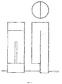
- Fig. 1 shows a first embodiment of the vapour lift tube of the present invention.
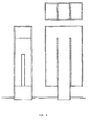
- Fig. 2-5 shows alternative embodiments of the vapour lift tube of the present invention.
- FIG. 1 One leg (downflow tube 1) of the inverted " U " opening 4 between the legs.
- the device provides thereby a flow path across the tray - inlet through the end of the short leg, vertical flow through the short leg, direction change at the top of the inverted " U ", downflow through the long leg and discharge through the open end of the long leg below the tray.
- a vertical slot 5 is cut into the side of the short leg opposite the longer leg.
- the top of the slot is at or below the bottom of the internal opening between legs.
- two or more slots could be cut into the short leg sides adjacent to or opposite the longer leg.
- a liquid level will be established on the tray.
- the liquid level on the vapour lift tube will be above the bottom of the short leg but below the top of the slot in the short leg.
- Vapour will pass through the slot in the short leg creating a pressure drop between the inside and outside of the vapour lift tube. Due to the lower pressure inside the vapour lift tube, the liquid level will be higher inside than outside the vapour lift tube.
- the vapour and liquid will mix in the shorter leg with the vapour lifting the liquid to flow up and over the connecting wall between the shorter and longer legs. Liquid will partially disengage, while flowing over the connecting wall and down the longer leg. At the opening under the tray, the liquid and vapour will further disengage with the liquid draining off the drip edge.
- FIG. 2 Alternative versions of the vapour lift tube design are shown on Fig. 2, 3, 4 and 5.
- the legs of the inverted " U " have square or rectangular cross sections.
- the device is composed of a single round tube 6 with a vertical baffle 7 to form the short and long legs.
- the device is composed of a pair of non-concentric round tubes, 8 and 9.
- the long leg is the smaller diameter tube 9 while the short leg is the annular space 10 inside the larger tube 8.
- an " M " shaped device is used with the outer legs being the equivalent of the short legs and the middle leg being the equivalent of the long leg. This version would be used where there is high liquid and vapour loadings.
- Fig. 5 is the same basic concept as Fig. 4 with the exception that the centre leg is a round tube.
- the top has been illustrated as being a flat plate. The top could also be rounded, domed, peaked or any other geometry.
- vapour lift tube The preferred version of the vapour lift tube is the design shown in Fig. 5. This version can be designed to operate over a wide range of vapour-liquid loads, maintains the geometric relationships necessary for functionality and can be fabricated economically and efficiently.
- the known trough type distribution device is mechanically complex and very sensitive to levelness. Depending on the design of the transitions between troughs, the quality of the distribution may also be susceptible to fouling.
- the known perforated plate design is similar to the chimney design.
- the chimney design is preferred since it can be designed for a wider range of liquid/vapour loadings and is less susceptible to fouling.
- vapour lift tube device over a chimney type design is the significantly wider turndown range possible with the vapour lift tube.
- a properly designed chimney must either become taller or have smaller holes drilled in the side. Due to fabricating tolerances, care of installation and deflection due to operating load, not all of the distribution devices will be at the same level in the vessel. At some level of turndown, some holes will be covered with liquid and others will not. This results in uneven liquid distribution over the surface below the tray.
- the vapour lift tube device will reduce the liquid flow difference between vapour lift tubes at different elevations better than what can be achieved with a chimney type design.
- a further advantage of the vapour lift tube over the chimney type design is the increased contacting of the liquid and vapour phases. The intimate contacting that occurs in the upflow portion of the vapour lift tube provides closer approaches to thermal and compositional equilibrium than would be achieved in the chimney tray.
- the vapour lift tube device is similar to the bubble cap device in concept but has several advantages. Since the vapour lift tube device is smaller, more can be placed on a distribution tray to achieve better distribution of liquid. Furthermore, since typical spacing patterns are square or triangular pitch, there are usually gaps in liquid distribution coverage near the vessel wall. With a smaller spacing, the size of these gaps are smaller. Overall wetting efficiency below the tray is better with a smaller pitch than with a larger pitch.
- the bubble cap design tray is limited to relatively large spacing and additional measures have been attempted to improve the liquid flow from the cap, e.g. the shear plate described in the Shih patent. Increasing the number of bubble caps with reduced spacing would increase the number of distribution points, but would negatively impact on the liquid/vapour flow relationships through each cap.
- vapour lift tube device A further advantage for the vapour lift tube device is that its simplicity makes it easier and less costly to fabricate in the optimal size proscribed by the process conditions.
- the liquid distribution trays of this invention will typically be used in hydroprocessing reactors. By obtaining even distribution of the liquid reactants over the entire reactor cross sectional area, all the catalyst at a given level is evenly wetted. Thus, all the catalysts at a given level operate at the same efficiency, which increases the overall efficiency of the reactor. Additionally, even liquid distribution maintains even radial temperature profiles across the reactor. This results in minimizing peak reactor temperatures which, over time reduces coking and catalyst deactivation rate. Consequently, the reactor operates more efficiently and with a longer cycle length. Value is achieved by reduced catalyst requirements, higher processing capability and/or longer cycle lengths.
- the device will work for any two phase downflow reactor or contactor. Typical applications would be in hydrotreating, hydrocracking, aromatic saturation, catalytic dewaxing and hydrofinishing reactors.
- the distribution performance of the vapour lift distributor has been tested against the traditional bubble cap (U.S. Patent No. 3,218,249, Example IV) at atmospheric pressure, ambient temperature and with water and air.
- the bubble cap used in this test is shown in the above U.S. Patent.
- the dimensions were as follows:
- the riser was a steel tube having an outer diameter of 79 mm, wall thickness of 2.11 mm and a height of 180 mm.
- the cap was made of 111 mm inner diameter steel pipe with a wall thickness of 2.11 mm and height of 129 mm with the upper end closed by a flat steel plate. Spacers were provided in the annular space between riser and cap. Each cap was provided with seven equally spaced slots 6.4 mm wide and 64 mm high. The vertical height from top of the riser to the inner wall of the cap was 19 mm.
- vapour lift tube used in the test is shown in Fig. 4.
- the test was conducted in a test rig with two identical distributors mounted on a tray plate.
- the two distributors were mounted 10 mm out off level. Water and air were fed to the tray at controlled rates.
- the water exiting each of the two distributors was collected simultaneously in two containers over a certain time period.
- the content of the containers was weighted in order to find the flow from the low distributor and the flow from the high distributor.
- Sensitivity 2 ⁇ W low - W high W low + W high ⁇ 100%
- vapour/liquid flow does vary from unit to unit depending upon the composition of the oil, treatgas rate and composition and operating pressure and temperature of the reactor.
- Three typical vapour/liquid load cases were simulated in the experiment: a high liquid load case, a medium liquid load case and a low liquid load case.
- vapour/liquid flow will be different for operation at low reactor temperature and fresh catalyst (Start of Run: SOR) than for operation with high reactor temperature and deactivated catalyst (End Of Run: EOR). This effect was also simulated in the test.
- vapour lift tubes have significant better distribution performance than the bubble cap distributor.
- the sensitivity of liquid flow towards level is about 4 times higher for the bubble cap distributor than it is for the vapour lift distributor.
Landscapes
- Chemical & Material Sciences (AREA)
- Chemical Kinetics & Catalysis (AREA)
- Organic Chemistry (AREA)
- Physical Or Chemical Processes And Apparatus (AREA)
- Vaporization, Distillation, Condensation, Sublimation, And Cold Traps (AREA)
- Production Of Liquid Hydrocarbon Mixture For Refining Petroleum (AREA)
- Hydrogen, Water And Hydrids (AREA)
- Feeding, Discharge, Calcimining, Fusing, And Gas-Generation Devices (AREA)
Applications Claiming Priority (2)
| Application Number | Priority Date | Filing Date | Title |
|---|---|---|---|
| US3350196P | 1996-12-19 | 1996-12-19 | |
| US33501P | 1996-12-19 |
Publications (4)
| Publication Number | Publication Date |
|---|---|
| EP0848974A2 true EP0848974A2 (fr) | 1998-06-24 |
| EP0848974A3 EP0848974A3 (fr) | 1999-12-08 |
| EP0848974B1 EP0848974B1 (fr) | 2005-10-12 |
| EP0848974B2 EP0848974B2 (fr) | 2010-12-15 |
Family
ID=21870761
Family Applications (1)
| Application Number | Title | Priority Date | Filing Date |
|---|---|---|---|
| EP97121495A Expired - Lifetime EP0848974B2 (fr) | 1996-12-19 | 1997-12-06 | Dispositif de distribution de deux phases à courant descendant |
Country Status (8)
| Country | Link |
|---|---|
| US (1) | US5942162A (fr) |
| EP (1) | EP0848974B2 (fr) |
| JP (1) | JP3900222B2 (fr) |
| AU (1) | AU723583B2 (fr) |
| CA (1) | CA2224696C (fr) |
| DE (1) | DE69734344T3 (fr) |
| ES (1) | ES2251010T5 (fr) |
| RU (1) | RU2192303C2 (fr) |
Cited By (5)
| Publication number | Priority date | Publication date | Assignee | Title |
|---|---|---|---|---|
| WO2004033065A1 (fr) * | 2002-10-08 | 2004-04-22 | Uop Llc | Appareil de distribution biphase et procede associe |
| WO2006076923A1 (fr) * | 2005-01-21 | 2006-07-27 | Morten Müller Ltd. Aps | Dispositif de distribution pour des cuves a circulation descendante simultanee a deux phases |
| EP3342481A4 (fr) * | 2015-08-28 | 2018-07-18 | LG Chem, Ltd. | Distributeur et réacteur catalytique à flux descendant comprenant celui-ci |
| CN109464967A (zh) * | 2018-11-14 | 2019-03-15 | 中石化炼化工程(集团)股份有限公司 | 一种气液分配器的中心管、气液分配器及气液分配盘 |
| EP1708797B1 (fr) * | 2004-01-15 | 2019-09-04 | Haldor Topsøe A/S | Plateau de distribution de vapeur et de liquide |
Families Citing this family (19)
| Publication number | Priority date | Publication date | Assignee | Title |
|---|---|---|---|---|
| DE60133590T2 (de) * | 2000-11-11 | 2009-06-04 | Haldor Topsoe A/S | Methode zum Nachrüsten von Hydrobehandlungsreaktoren |
| US7473405B2 (en) * | 2004-10-13 | 2009-01-06 | Chevron U.S.A. Inc. | Fluid distribution apparatus for downflow multibed poly-phase catalytic reactor |
| JP4413759B2 (ja) * | 2004-12-02 | 2010-02-10 | 株式会社沖データ | ベルト駆動装置及びそれを有する画像形成装置 |
| US7506861B2 (en) * | 2005-01-21 | 2009-03-24 | Morten Muller Ltd. Aps | Distribution device for two-phase concurrent downflow vessels |
| TWI267060B (en) * | 2005-05-11 | 2006-11-21 | Benq Corp | Display apparatuses, methods and machine-readable storage medium for adjusting display parameter based on display content |
| DE602006000497D1 (de) | 2005-05-13 | 2008-03-20 | Haldor Topsoe As | Verteilervorrichtung für abwärtsfließende Reaktoren mit mindesten einer unterteilten Schornsteinkammer |
| PT2078552E (pt) | 2008-01-09 | 2014-07-31 | Haldor Topsoe As | Dispositivo de distribuição líquido-vapor |
| US8202498B2 (en) | 2010-07-19 | 2012-06-19 | Chevron U.S.A. Inc. | Multiphase contact and distribution apparatus for hydroprocessing |
| US8372354B2 (en) | 2010-07-19 | 2013-02-12 | Chevron U.S.A. Inc. | Multiphase contact and distribution apparatus for hydroprocessing |
| FR2964325B1 (fr) | 2010-09-03 | 2013-01-04 | IFP Energies Nouvelles | Dispositif de distribution d'un melange polyphasique comportant un plateau brise-jet avec element de separation |
| FR2964327B1 (fr) | 2010-09-03 | 2012-09-28 | IFP Energies Nouvelles | Dispositif de distribution d'un melange polyphasique comportant un plateau brise-jet perfore avec differents types de trous |
| US8517353B2 (en) * | 2010-09-27 | 2013-08-27 | Uop Llc | Apparatus and process for distributing vapor and liquid phases |
| US8695953B2 (en) | 2010-12-06 | 2014-04-15 | Uop Llc | Distribution tray, vessel, or method relating thereto |
| CN102240526B (zh) * | 2011-05-12 | 2013-07-10 | 中国石油天然气集团公司 | 气提式液体分布器和反应器内构件 |
| FR2978679B1 (fr) | 2011-08-03 | 2014-01-17 | Total Raffinage Marketing | Plateau distributeur d'un gaz et d'un liquide, reacteur equipe d'un tel plateau et utilisation dudit plateau. |
| FR2982172B1 (fr) * | 2011-11-03 | 2013-11-01 | Ifp Energies Now | Plateau de distribution d'un melange gaz liquide equipe d'elements de distribution peu sensibles au defaut d'horizontalite |
| KR102001608B1 (ko) * | 2015-08-28 | 2019-07-18 | 주식회사 엘지화학 | 분배기 및 이를 포함하는 하강류 촉매 반응기 |
| SA118400251B1 (ar) | 2018-02-23 | 2021-12-06 | انديان اويل كوربوريشن ليمتد | توزيع مُحسّن لخليط مائع متعدد الأطوار |
| US11168266B2 (en) * | 2019-11-21 | 2021-11-09 | Saudi Arabian Oil Company | Heavy aromatic solvents for catalyst reactivation |
Citations (6)
| Publication number | Priority date | Publication date | Assignee | Title |
|---|---|---|---|---|
| US3218249A (en) * | 1964-03-30 | 1965-11-16 | Union Oil Co | Vapor-liquid distribution method and apparatus for the conversion of hydrocarbons |
| US3914352A (en) * | 1973-12-26 | 1975-10-21 | Univ Delaware | Bubble cap tray |
| US4126540A (en) * | 1973-08-03 | 1978-11-21 | Atlantic Richfield Company | Apparatus and process for distributing a mixed phase through solids |
| US4510023A (en) * | 1983-06-17 | 1985-04-09 | Air Products And Chemicals, Inc. | Perforated bubble caps for enhanced vapor/liquid contact on a distillation tray |
| US5158714A (en) * | 1991-05-30 | 1992-10-27 | Union Oil Company Of California | Vapor-liquid distribution method and apparatus |
| US5265428A (en) * | 1990-10-05 | 1993-11-30 | Exxon Production Research Company | Bubble cap tray for melting solids and method for using same |
Family Cites Families (13)
| Publication number | Priority date | Publication date | Assignee | Title |
|---|---|---|---|---|
| CA580128A (fr) * | 1959-07-28 | Kittel Walter | Plaque de contact pour usage dans colonne de redressage ou de contact | |
| US2125343A (en) * | 1935-04-18 | 1938-08-02 | Ig Farbenindustrie Ag | Column containing filler bodies |
| US2416724A (en) * | 1944-10-09 | 1947-03-04 | Phillips Petroleum Co | Fractionation apparatus |
| GB877018A (en) * | 1958-07-28 | 1961-09-13 | Stage Hermann | Column for gas-liquid contacting |
| US3353924A (en) * | 1965-07-16 | 1967-11-21 | Shell Oil Co | Bed reactor with quench deck |
| US3524731A (en) * | 1968-09-30 | 1970-08-18 | Exxon Research Engineering Co | Mixed-phase flow distributor for packed beds |
| US3598539A (en) * | 1968-12-11 | 1971-08-10 | Universal Oil Prod Co | Vessel for contacting fluids and a bed of granular solids |
| US3824081A (en) * | 1972-04-27 | 1974-07-16 | Texaco Inc | Vertical reactor for two-phase vapor-liquid reaction charge |
| US3972966A (en) * | 1975-01-21 | 1976-08-03 | Universal Oil Products Company | Apparatus for producing pulsed liquid flow in a distillation column |
| US4140625A (en) * | 1977-12-19 | 1979-02-20 | Uop Inc. | Mixed-phase distributor for fixed-bed catalytic reaction chambers |
| US4836989A (en) * | 1987-07-02 | 1989-06-06 | Mobil Oil Corporation | Distribution system for downflow reactors |
| US4960571A (en) * | 1988-12-14 | 1990-10-02 | Exxon Research And Engineering Company | Quench assembly design |
| US5192465A (en) * | 1991-02-05 | 1993-03-09 | Glitsch, Inc. | Method of and apparatus for liquid distribution |
-
1997
- 1997-12-06 ES ES97121495T patent/ES2251010T5/es not_active Expired - Lifetime
- 1997-12-06 EP EP97121495A patent/EP0848974B2/fr not_active Expired - Lifetime
- 1997-12-06 DE DE69734344T patent/DE69734344T3/de not_active Expired - Lifetime
- 1997-12-12 CA CA002224696A patent/CA2224696C/fr not_active Expired - Lifetime
- 1997-12-17 AU AU48444/97A patent/AU723583B2/en not_active Expired
- 1997-12-18 JP JP34957097A patent/JP3900222B2/ja not_active Expired - Lifetime
- 1997-12-18 US US08/993,308 patent/US5942162A/en not_active Expired - Lifetime
- 1997-12-18 RU RU97122099/12A patent/RU2192303C2/ru active
Patent Citations (6)
| Publication number | Priority date | Publication date | Assignee | Title |
|---|---|---|---|---|
| US3218249A (en) * | 1964-03-30 | 1965-11-16 | Union Oil Co | Vapor-liquid distribution method and apparatus for the conversion of hydrocarbons |
| US4126540A (en) * | 1973-08-03 | 1978-11-21 | Atlantic Richfield Company | Apparatus and process for distributing a mixed phase through solids |
| US3914352A (en) * | 1973-12-26 | 1975-10-21 | Univ Delaware | Bubble cap tray |
| US4510023A (en) * | 1983-06-17 | 1985-04-09 | Air Products And Chemicals, Inc. | Perforated bubble caps for enhanced vapor/liquid contact on a distillation tray |
| US5265428A (en) * | 1990-10-05 | 1993-11-30 | Exxon Production Research Company | Bubble cap tray for melting solids and method for using same |
| US5158714A (en) * | 1991-05-30 | 1992-10-27 | Union Oil Company Of California | Vapor-liquid distribution method and apparatus |
Cited By (8)
| Publication number | Priority date | Publication date | Assignee | Title |
|---|---|---|---|---|
| WO2004033065A1 (fr) * | 2002-10-08 | 2004-04-22 | Uop Llc | Appareil de distribution biphase et procede associe |
| CN1323742C (zh) * | 2002-10-08 | 2007-07-04 | 环球油品公司 | 两相分配装置和方法 |
| EP1708797B1 (fr) * | 2004-01-15 | 2019-09-04 | Haldor Topsøe A/S | Plateau de distribution de vapeur et de liquide |
| WO2006076923A1 (fr) * | 2005-01-21 | 2006-07-27 | Morten Müller Ltd. Aps | Dispositif de distribution pour des cuves a circulation descendante simultanee a deux phases |
| EA011977B1 (ru) * | 2005-01-21 | 2009-06-30 | Мортен Мюллер Лтд. Апс | Распределительное устройство для ёмкостей с двухфазными спутными нисходящими потоками |
| EP3342481A4 (fr) * | 2015-08-28 | 2018-07-18 | LG Chem, Ltd. | Distributeur et réacteur catalytique à flux descendant comprenant celui-ci |
| US10792635B2 (en) | 2015-08-28 | 2020-10-06 | Lg Chem, Ltd. | Distributor and down flow catalytic reactor comprising same |
| CN109464967A (zh) * | 2018-11-14 | 2019-03-15 | 中石化炼化工程(集团)股份有限公司 | 一种气液分配器的中心管、气液分配器及气液分配盘 |
Also Published As
| Publication number | Publication date |
|---|---|
| MX9710421A (es) | 1998-09-30 |
| EP0848974B2 (fr) | 2010-12-15 |
| ES2251010T5 (es) | 2011-04-26 |
| US5942162A (en) | 1999-08-24 |
| EP0848974A3 (fr) | 1999-12-08 |
| RU2192303C2 (ru) | 2002-11-10 |
| EP0848974B1 (fr) | 2005-10-12 |
| ES2251010T3 (es) | 2006-04-16 |
| AU723583B2 (en) | 2000-08-31 |
| DE69734344T2 (de) | 2006-05-11 |
| JPH10230156A (ja) | 1998-09-02 |
| AU4844497A (en) | 1998-06-25 |
| DE69734344T3 (de) | 2011-04-21 |
| JP3900222B2 (ja) | 2007-04-04 |
| CA2224696C (fr) | 2003-04-29 |
| DE69734344D1 (de) | 2006-02-23 |
| CA2224696A1 (fr) | 1998-06-19 |
Similar Documents
| Publication | Publication Date | Title |
|---|---|---|
| EP0848974B1 (fr) | Dispositif de distribution de deux phases à courant descendant | |
| US7600742B2 (en) | Vapour-liquid distribution tray | |
| CA2190844C (fr) | Systeme de distribution de deux phases pour reacteurs a ecoulement descendant | |
| EP2078552B1 (fr) | Dispositif de distribution vapeur-liquide | |
| KR100833826B1 (ko) | 액체 혼합용 교반실을 갖는 혼합 장치 | |
| US5837208A (en) | Hydroprocessing reactor mixer/distributor | |
| AU699855B2 (en) | Distributor device for multiple-bed downflow reactors | |
| CN112533682B (zh) | 用于传质塔的包括固定阀和可动阀的多程接触托盘和涉及该多程接触托盘的方法 | |
| MXPA97010421A (en) | Distribution device for flowing liquid descending in two fa | |
| Bingham et al. | Advanced reactor internals for hydroprocessing units |
Legal Events
| Date | Code | Title | Description |
|---|---|---|---|
| PUAI | Public reference made under article 153(3) epc to a published international application that has entered the european phase |
Free format text: ORIGINAL CODE: 0009012 |
|
| AK | Designated contracting states |
Kind code of ref document: A2 Designated state(s): BE CH DE DK ES FI FR GB IT LI NL SE |
|
| AX | Request for extension of the european patent |
Free format text: AL;LT;LV;MK;RO;SI |
|
| PUAL | Search report despatched |
Free format text: ORIGINAL CODE: 0009013 |
|
| AK | Designated contracting states |
Kind code of ref document: A3 Designated state(s): AT BE CH DE DK ES FI FR GB GR IE IT LI LU MC NL PT SE |
|
| AX | Request for extension of the european patent |
Free format text: AL;LT;LV;MK;RO;SI |
|
| RIC1 | Information provided on ipc code assigned before grant |
Free format text: 6B 01D 3/26 A, 6B 01D 3/20 B, 6C 10G 49/00 B, 6B 01D 3/32 B |
|
| 17P | Request for examination filed |
Effective date: 20000608 |
|
| AKX | Designation fees paid |
Free format text: BE CH DE DK ES FI FR GB IT LI NL SE |
|
| 17Q | First examination report despatched |
Effective date: 20010709 |
|
| GRAP | Despatch of communication of intention to grant a patent |
Free format text: ORIGINAL CODE: EPIDOSNIGR1 |
|
| GRAS | Grant fee paid |
Free format text: ORIGINAL CODE: EPIDOSNIGR3 |
|
| GRAA | (expected) grant |
Free format text: ORIGINAL CODE: 0009210 |
|
| AK | Designated contracting states |
Kind code of ref document: B1 Designated state(s): BE CH DE DK ES FI FR GB IT LI NL SE |
|
| PG25 | Lapsed in a contracting state [announced via postgrant information from national office to epo] |
Ref country code: LI Free format text: LAPSE BECAUSE OF FAILURE TO SUBMIT A TRANSLATION OF THE DESCRIPTION OR TO PAY THE FEE WITHIN THE PRESCRIBED TIME-LIMIT Effective date: 20051012 Ref country code: CH Free format text: LAPSE BECAUSE OF FAILURE TO SUBMIT A TRANSLATION OF THE DESCRIPTION OR TO PAY THE FEE WITHIN THE PRESCRIBED TIME-LIMIT Effective date: 20051012 Ref country code: BE Free format text: LAPSE BECAUSE OF FAILURE TO SUBMIT A TRANSLATION OF THE DESCRIPTION OR TO PAY THE FEE WITHIN THE PRESCRIBED TIME-LIMIT Effective date: 20051012 |
|
| REG | Reference to a national code |
Ref country code: GB Ref legal event code: FG4D |
|
| REG | Reference to a national code |
Ref country code: CH Ref legal event code: EP |
|
| PG25 | Lapsed in a contracting state [announced via postgrant information from national office to epo] |
Ref country code: SE Free format text: LAPSE BECAUSE OF FAILURE TO SUBMIT A TRANSLATION OF THE DESCRIPTION OR TO PAY THE FEE WITHIN THE PRESCRIBED TIME-LIMIT Effective date: 20060112 Ref country code: DK Free format text: LAPSE BECAUSE OF FAILURE TO SUBMIT A TRANSLATION OF THE DESCRIPTION OR TO PAY THE FEE WITHIN THE PRESCRIBED TIME-LIMIT Effective date: 20060112 |
|
| REF | Corresponds to: |
Ref document number: 69734344 Country of ref document: DE Date of ref document: 20060223 Kind code of ref document: P |
|
| REG | Reference to a national code |
Ref country code: ES Ref legal event code: FG2A Ref document number: 2251010 Country of ref document: ES Kind code of ref document: T3 |
|
| REG | Reference to a national code |
Ref country code: CH Ref legal event code: PL |
|
| ET | Fr: translation filed | ||
| PLBI | Opposition filed |
Free format text: ORIGINAL CODE: 0009260 |
|
| 26 | Opposition filed |
Opponent name: UOP LLC P.O. BOX 5017 Effective date: 20060630 |
|
| PLAX | Notice of opposition and request to file observation + time limit sent |
Free format text: ORIGINAL CODE: EPIDOSNOBS2 |
|
| NLR1 | Nl: opposition has been filed with the epo |
Opponent name: UOP LLC P.O. BOX 5017 |
|
| PLBB | Reply of patent proprietor to notice(s) of opposition received |
Free format text: ORIGINAL CODE: EPIDOSNOBS3 |
|
| APAH | Appeal reference modified |
Free format text: ORIGINAL CODE: EPIDOSCREFNO |
|
| APBP | Date of receipt of notice of appeal recorded |
Free format text: ORIGINAL CODE: EPIDOSNNOA2O |
|
| APBQ | Date of receipt of statement of grounds of appeal recorded |
Free format text: ORIGINAL CODE: EPIDOSNNOA3O |
|
| PLAB | Opposition data, opponent's data or that of the opponent's representative modified |
Free format text: ORIGINAL CODE: 0009299OPPO |
|
| R26 | Opposition filed (corrected) |
Opponent name: UOP LLC P.O. BOX 5017 Effective date: 20060630 |
|
| APBU | Appeal procedure closed |
Free format text: ORIGINAL CODE: EPIDOSNNOA9O |
|
| PUAH | Patent maintained in amended form |
Free format text: ORIGINAL CODE: 0009272 |
|
| STAA | Information on the status of an ep patent application or granted ep patent |
Free format text: STATUS: PATENT MAINTAINED AS AMENDED |
|
| 27A | Patent maintained in amended form |
Effective date: 20101215 |
|
| AK | Designated contracting states |
Kind code of ref document: B2 Designated state(s): BE CH DE DK ES FI FR GB IT LI NL SE |
|
| REG | Reference to a national code |
Ref country code: NL Ref legal event code: T3 |
|
| REG | Reference to a national code |
Ref country code: ES Ref legal event code: DC2A Ref document number: 2251010 Country of ref document: ES Kind code of ref document: T5 Effective date: 20110426 |
|
| REG | Reference to a national code |
Ref country code: FR Ref legal event code: PLFP Year of fee payment: 19 |
|
| REG | Reference to a national code |
Ref country code: FR Ref legal event code: PLFP Year of fee payment: 20 |
|
| PG25 | Lapsed in a contracting state [announced via postgrant information from national office to epo] |
Ref country code: IT Free format text: LAPSE BECAUSE OF NON-PAYMENT OF DUE FEES Effective date: 20151206 |
|
| PGFP | Annual fee paid to national office [announced via postgrant information from national office to epo] |
Ref country code: NL Payment date: 20161226 Year of fee payment: 20 Ref country code: FI Payment date: 20161229 Year of fee payment: 20 Ref country code: GB Payment date: 20161228 Year of fee payment: 20 |
|
| PGFP | Annual fee paid to national office [announced via postgrant information from national office to epo] |
Ref country code: FR Payment date: 20161227 Year of fee payment: 20 Ref country code: ES Payment date: 20161227 Year of fee payment: 20 |
|
| PGFP | Annual fee paid to national office [announced via postgrant information from national office to epo] |
Ref country code: DE Payment date: 20161229 Year of fee payment: 20 |
|
| PG25 | Lapsed in a contracting state [announced via postgrant information from national office to epo] |
Ref country code: IT Free format text: LAPSE BECAUSE OF NON-PAYMENT OF DUE FEES Effective date: 20151206 |
|
| PGFP | Annual fee paid to national office [announced via postgrant information from national office to epo] |
Ref country code: IT Payment date: 20161222 Year of fee payment: 20 |
|
| PGRI | Patent reinstated in contracting state [announced from national office to epo] |
Ref country code: IT Effective date: 20170710 |
|
| REG | Reference to a national code |
Ref country code: DE Ref legal event code: R071 Ref document number: 69734344 Country of ref document: DE Ref country code: NL Ref legal event code: MK Effective date: 20171205 |
|
| REG | Reference to a national code |
Ref country code: GB Ref legal event code: PE20 Expiry date: 20171205 |
|
| PG25 | Lapsed in a contracting state [announced via postgrant information from national office to epo] |
Ref country code: GB Free format text: LAPSE BECAUSE OF EXPIRATION OF PROTECTION Effective date: 20171205 |
|
| REG | Reference to a national code |
Ref country code: ES Ref legal event code: FD2A Effective date: 20180326 |
|
| PG25 | Lapsed in a contracting state [announced via postgrant information from national office to epo] |
Ref country code: ES Free format text: LAPSE BECAUSE OF EXPIRATION OF PROTECTION Effective date: 20171207 |