EP0848352A1 - Medium-handling device and medium-handling method - Google Patents
Medium-handling device and medium-handling method Download PDFInfo
- Publication number
- EP0848352A1 EP0848352A1 EP96928690A EP96928690A EP0848352A1 EP 0848352 A1 EP0848352 A1 EP 0848352A1 EP 96928690 A EP96928690 A EP 96928690A EP 96928690 A EP96928690 A EP 96928690A EP 0848352 A1 EP0848352 A1 EP 0848352A1
- Authority
- EP
- European Patent Office
- Prior art keywords
- medium
- feed passage
- ticket
- disposed
- feed
- Prior art date
- Legal status (The legal status is an assumption and is not a legal conclusion. Google has not performed a legal analysis and makes no representation as to the accuracy of the status listed.)
- Granted
Links
Images

Classifications
-
- G—PHYSICS
- G07—CHECKING-DEVICES
- G07B—TICKET-ISSUING APPARATUS; FARE-REGISTERING APPARATUS; FRANKING APPARATUS
- G07B3/00—Machines for issuing preprinted tickets
- G07B3/04—Machines for issuing preprinted tickets from a stack
-
- G—PHYSICS
- G07—CHECKING-DEVICES
- G07B—TICKET-ISSUING APPARATUS; FARE-REGISTERING APPARATUS; FRANKING APPARATUS
- G07B1/00—Machines for printing and issuing tickets
-
- B—PERFORMING OPERATIONS; TRANSPORTING
- B65—CONVEYING; PACKING; STORING; HANDLING THIN OR FILAMENTARY MATERIAL
- B65H—HANDLING THIN OR FILAMENTARY MATERIAL, e.g. SHEETS, WEBS, CABLES
- B65H2701/00—Handled material; Storage means
- B65H2701/10—Handled articles or webs
- B65H2701/18—Form of handled article or web
- B65H2701/182—Piled package
- B65H2701/1824—Web material folded in zig-zag form
Definitions
- the present invention relates to a medium handling apparatus including a desktop ticket issuing apparatus connected with a host machine for issuing tickets, and a medium handling method used when issuing the tickets.
- a conventional medium handling apparatus will be now described by exemplifying a ticket issuing apparatus which is connected with a host machine for issuing tickets.
- the conventional medium handling apparatus comprises a plurality of hoppers for accommodating therein a rectangular ticket sheet which is folded along perforations, a medium separating part for separating the ticket sheet, a magnetic processing part for writing a magnetic data into the ticket sheet, a printing part for printing a printing data onto the ticket sheet, and a discharge stacker for discharging the ticket sheet wherein the plurality of hoppers are arranged horizontally and disposed at the lower part of a housing, and wherein the medium separating part, magnetic processing part, printing part and discharge stacker are respectively arranged horizontally and disposed at the upper part of each hopper.
- the ticket sheets are drawn out from each hopper like bellows, and they are separated one by one along the perforations by the medium separating part, and a given magnetic data is written into a magnetic stripe provided at the back of the ticket sheet by the magnetic processing part, then a given printing data is printed by the printing part onto the front side of the ticket sheet in the printing position, and finally the ticket sheet is discharged to the discharge stacker.
- the conventional medium handling apparatus has such a structure that the medium separating part, magnetic processing part and printing part are respectively arranged horizontally and disposed at the upper parts of the hoppers, and the ticket sheet is drawn out from each hopper like bellows and guided to these components. Accordingly, there occurs a problem that a space is needed for arranging the medium separating part, magnetic processing part and printing part respectively horizontally and disposing them at the upper parts of the hoppers, and another space is needed for drawing out the ticket sheet like bellows, which makes the apparatus large-sized.
- the conventional medium handling apparatus draws out the ticket sheet like bellows, then bends the ticket sheet largely and holds the ticket sheet in that state to prevent the ticket sheet from being deformed.
- the ticket sheet which is first issued from the apparatus curls by the heat generated therein, which causes a problem that it makes a client who receives the ticket sheet feel unpleasant.
- a medium handling apparatus comprises a plurality of medium accommodating parts for accommodating medium therein, a plurality of guides respectively having one ends connected with each of said medium accommodating parts and disposed in strata, and other ends merged into one to form a first feed passage, a second feed passage having one end connected with said first feed passage, a medium separating part for separating the medium into a given size, a magnetic processing part for writing a given magnetic data into the medium, a printing part for printing a given data onto the medium, and a discharge stacker for discharging the medium, wherein a feed passage formed by said first and second feed passages is disposed to pass through upper, rear and lower portions of said plurality of medium accommodating parts in this order, and is guided to a front wall of the apparatus, wherein the medium separating part, magnetic processing part and printing part are respectively disposed along the second feed passage, and wherein the discharge stacker is disposed at the front wall of said apparatus and is connected with another end of the second feed passage.
- the first aspect of the invention can provide a small-sized medium handling apparatus.
- a medium handling apparatus is characterized in that it further comprises in the first aspect of the invention a circular arc part disposed on the second feed passage for changing a direction of the medium toward said discharge stacker, a first insertion port disposed under said discharge stacker for inserting the medium from an outside of said apparatus into an inside of said apparatus, and a third feed passage having one end connected with said first insertion port, and another end connected with said second feed passage at said circular arc part for feeding the medium inserted from said first insertion port to the second feed passage.
- the second aspect of the invention can provide a medium handling apparatus capable of inserting a medium from the outside of the apparatus at the front side thereof to the inside thereof.
- a medium handling apparatus is characterized in that it further comprises in the second aspect of the invention detecting means disposed on said second or third feed passage for discriminating a length of medium inserted through said first insertion port, and a blade disposed at said circular arc part for changing a direction of the medium toward said discharge stacker.
- the third aspect of the invention can provide a medium handling apparatus capable of discriminating the length of medium and changing the feeding direction of the medium toward the discharge stacker.
- a medium handling apparatus is characterized in that it further comprises in the first aspect of the invention a second insertion port disposed at a back wall of the apparatus for inserting the medium from an outside of said apparatus into an inside of said apparatus, and a fourth feed passage having one end connected with said second insertion port, and another end connected with said first or second feed passage at backs of said plurality of medium accommodating parts for feeding the medium inserted from the second insertion port to a feed passage formed by said first and second feed passages.
- the fourth aspect of the invention can provide a medium handling apparatus capable of inserting medium from the outside of the apparatus at the back thereof to the inside thereof.
- a medium handling apparatus is characterized in comprising a feed passage for feeding a medium, a circular arc part disposed on said feed passage for changing a direction of the medium to be fed along said feed passage, and a pressing member disposed at an upper or a lower part of said circular arc part for making a feeding distance of the medium constant.
- the fifth aspect of the invention can provide a medium handling apparatus capable of making the feeding distance of the medium constant.
- a medium handling method comprises is characterized in removing curl of medium by moving and returning said medium before it is issued plural times in a feed passage, which is curved in a direction to remove the curl of the medium.
- a medium handling method comprises is characterized in guiding a medium from medium accommodating parts each accommodating the medium therein upstream relative to a medium separating part, feeding the medium to the medium separating part for separating the medium one by one by the medium separating part when the medium is issued, then issuing the medium, wherein the medium is returned to a given amount to the medium accommodation parts before it is issued so as to remove curl of the medium.
- the sixth and seventh aspects of the invention can remove the curl of medium to issue the medium without deforming the medium.
- Fig. 1 is a schematic layout view showing a typical structure of a ticket issuing apparatus according to an embodiment of the present invention.
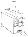
- Fig. 2 is a perspective view showing an external appearance of the ticket issuing apparatus.
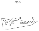
- Fig. 3 is a cross sectional view showing a blade in detail.
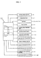
- Fig. 4 is a block diagram showing the control of the ticket issuing apparatus.
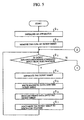
- Fig. 5 is a first flow chart showing an operation of the ticket issuing apparatus.
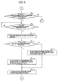
- Fig. 6 is a second flow chart showing an operation of the ticket issuing apparatus.
- a medium handling according to an embodiment of the invention will be described hereinafter with reference to the attached drawings, by exemplifying a ticket issuing apparatus for issuing tickets while it is connected with a host machine.
- Components which are common to each drawing are denoted by the same numerals.
- Fig. 1 is a schematic layout view showing a typical structure of a ticket issuing apparatus according to the embodiment of the present invention.
- Fig. 2 is a perspective view showing an external appearance of the ticket issuing apparatus.
- Fig. 1 corresponds to the figure taken along the arrow A-A in Fig. 2.
- a ticket issuing apparatus denoted by 1 is a ticket issuing apparatus, 2 is a housing, 3 is an operation panel, 4 is a ticket sheet, 5 is a ticket issuance port, 6 is a ticket insertion port, 7 is a ticket to be inserted, and 8 is a power source switch.
- the ticket issuing apparatus 1 has the operation panel 3 at the front wall of the housing 2.
- the operation panel 3 has the ticket issuance port 5 for issuing the ticket sheet 4 and also has the ticket insertion port 6 under the ticket issuance port 5 for inserting an airline ticket when it is changed to a boarding ticket.
- the ticket to be inserted from the ticket insertion port 6 is hereinafter referred to as the ticket 7.
- the ticket 7 is a medium which is differentiated in length depending on a kind thereof.
- the ticket issuing apparatus 1 has the power source switch 8 at the rear portion of the side wall of the housing 2.
- the ticket issuing apparatus 1 is structured to be divided into a main body and a side cover along the cut line A-A, and it is illustrated in Fig. 1 where the side cover is removed from the main body.
- Fig. 1 denoted by 4a is perforations, 9 is a discharge stacker, 10 and 11 are hoppers, 12 is a medium separating roller, 13 is a magnetic processing part, 13a and 13b are magnetic heads, 14 is a printing part, 15 is a feed passage, 16 is a first circular arc part, 17 is a second circular arc part, 18 is a third circular arc part, 19 is a leaf spring, 20 is a branched path, 21 is a blade, 22a to 22k are feed rollers, 23a to 23g are sensors, 24 is platen rollers, 25 is a thermal head, 26 is a ribbon rewinding part, and 27 is a ribbon winding part.
- the ticket issuing apparatus 1 has the discharge stacker 9 inside the ticket issuance port 5 so that the ticket sheet 4 is issued through the ticket issuance port 5 while the perforations 4a of the ticket sheet 4 protrude upward from the ticket issuance port 5.
- the discharge stacker 9 is disposed aslant inside the ticket issuance port 5. The reason why the discharge stacker 9 is disposed aslant is that firstly the ticket sheet 4 is discharged in a state where it is lined up so that a client easily receives the ticket sheet 4, secondly the discharge stacker 9 does not protrude outside the apparatus so that the apparatus can be made small sized.
- the ticket issuing apparatus 1 has the hoppers 10 and 11, medium separating roller 12, magnetic processing part 13 and printing part 14 in the housing 2. These components are disposed in the manner that the hoppers 10 and 11 and the medium separating roller 12 are directed from behind the ticket issuance port 5 which is disposed at the front wall of the apparatus toward the back of the ticket issuing apparatus 1 in this order and arranged adjacent to one another.
- the magnetic processing part 13 and printing part 14 are disposed under the hoppers 10 and 11 while the former is in parallel with the latter.
- the hoppers 10 and 11 can accommodate therein rectangular tickets which are folded at perforations and have different length.
- the ticket issuing apparatus 1 draws out the ticket sheets 4 from the hoppers 10 and 11 to guide them to the medium separating roller 12.
- the medium separating roller 12 has a double-cone shape having the maximum diameter at the center thereof and the minim diameter at both ends thereof.
- the medium separating roller 12 separates the ticket sheet 4 one by one along every perforations.
- the ticket issuing apparatus 1 feeds the ticket sheet 4 which is separated one by one by the medium separating roller 12 to the magnetic processing part 13.
- the magnetic processing part 13 writes a given magnetic data into a magnetic stripe provided at the back of the ticket sheet 4 by a write magnetic head 13a, and reads the magnetic data by a read magnetic head 13b, and then it checks whether the magnetic data is written correctly or not.
- the ticket issuing apparatus 1 feeds the ticket sheet 4, magnetic data of which was checked by the magnetic processing part 13, to the printing part 14.
- the printing part 14 is a thermal printer for printing a given printing data onto the front of the ticket sheet 4 in a printing position.
- the ticket issuing apparatus 1 feeds the ticket sheet 4 onto which a given printing data was printed by the printing part 14 to the discharge stacker 9.
- the discharge stacker 9 discharges the ticket sheet 4 while lining up the ticket sheet 4 so that the perforations 4a of the ticket sheet 4 is directed upward to be jumped and issued through the ticket issuance port 5.
- the ticket issuing apparatus 1 has the feed passage 15 inside the housing 2.
- the feed passage 15 is disposed in the manner that it passes through the upper, rear and lower portions of the hoppers 10 and 11 in this order and it is guided to the ticket issuance port 5 disposed at the front wall of the apparatus. Meanwhile, the medium separating roller 12, magnetic processing part 13 and printing part 14 are disposed along the feed passage 15 while the discharge stacker 9 is disposed at the end of the feed passage 15.
- the feed passage 15 is branched into plural guides at one end thereof, which are respectively connected with the respective hoppers 10 and 11 and arranged in strata.
- the feed passage 15 is formed in a manner that one end thereof branched to plural guides is changed in a direction to be substantially perpendicular thereto by the first circular arc part 16, then the plural guides are merged into one so as to guide the ticket sheet 4 to the medium separating roller 12. Further, the feed passage 15 is formed in the manner that the portion between the medium separating roller 12 and magnetic processing part 13 is changed in a direction to be substantially perpendicular thereto by the second circular arc part 17. Still further, the feed passage 15 is formed in the manner that the portion between the magnetic processing part 13 and printing part 14 is changed in a direction by the third circular arc part 18 so that the printing part 14 is in parallel with the discharge stacker 9.
- the feed passage 15 having such an arrangement is structured that the ticket sheet 4 is not needed to be drawn out like bellows when it is guided from the hoppers 10 and 11 to the medium separating roller 12.
- the feed passage 15 is curved between the hoppers 10 and 11 and the first circular arc part 16, and also it is curved between the first circular arc part 16 and medium separating roller 12 in the direction opposite thereto.
- the ticket sheet 4 fed on the feed passage 15 is curled along the feed passage 15 between the hoppers 10 and 11 and the first circular arc part 16.
- the feed passage 15 can remove the curl of the ticket sheet 4 while moving and returning the ticket sheet 4 plural times between the first circular arc part 16 and the medium separating roller 12.
- the feed passage 15 is connected with the branched path 20 communicating with the ticket insertion port 6 through which the ticket 7 is inserted at the third circular arc part 18.
- the ticket 7 inserted into the inside of the apparatus through the ticket insertion port 6 is fed upstream relative to the magnetic processing part 13, then it is returned, and a given magnetic data is written into the ticket 7 by the magnetic processing part 13, and a given printing data is printed onto the ticket 7, and finally it is discharged through the discharge stacker 9.
- the feed passage 15 has the blade 21 for switching the feeding direction of the ticket sheet 4 and that of the ticket 7 at a merging part of the feed passage 15 and the branched path 20.
- the blade 21 is made of a resin material and is formed of a plurality of blade pieces which are disposed in a width direction of the ticket sheet 4 to be integrated with one another by a beam.
- the blade 21 is disposed at the merging part between the feed passage 15 and the branched path 20 so as to be freely turned about an axle, and it is driven by an electromagnetic solenoid, described later.
- the blade 21 is turned in the direction of the arrow B when the electromagnetic solenoid is turned on and it is turned in the direction of the arrow C by a bias spring (not shown) when the electromagnetic solenoid is turned off.
- the leaf spring 19 is fixed to the blade 21.
- the leaf spring 19 is a pressing member which is disposed to prevent the ticket sheet 4 from being varied in its printing position which is caused by the swelling in moving distance of the ticket sheet 4 when the ticket sheet 4 passes through the third circular arc part 18, and it presses the ticket sheet 4 against an upper feeding guide of the feed passage 15 to make the feeding distance of the ticket sheet 4 constant.
- the pressing member such as the leaf spring 19 can be disposed at either the upper or lower feeding guide of the feed passage 15 so as to press the ticket sheet 4 against either the upper or lower feeding guide.
- the pressing member can be disposed at circular arc parts other than the third circular arc part 18, particularly it is effective to be disposed at the spot where the moving distance of the ticket sheet 4 is required to be constant.
- the pressing member can be employed by a medium handling apparatus other than the ticket issuing apparatus 1, such as a copying machine, an optical character reader (OCR), and an automated teller machine (ATM).
- the ticket issuing apparatus 1 has, as shown in Fig. 1, a feeding pass at the rear wall of the housing 2 for guiding the ticket sheet 4 from an optional hopper (not shown) provided outside the apparatus to the inside of the apparatus.
- the ticket issuing apparatus 1 guides the ticket sheet 4 which is guided from the optional hopper to the inside of the medium separating roller 12, then it separates the ticket sheet 4 one by one along every perforation 4a.
- the medium separating roller 12 is disposed behind the hoppers 10 and 11.
- the medium separating roller 12 may be disposed at the portion expect behind the hoppers 10 and 11 but it is preferable to be disposed behind the hoppers 10 and 11 because of the following reason.
- the medium separating roller 12 guides the ticket sheet 4 which is accommodated into the optional hopper provided outside the apparatus to the inside of the apparatus to separate the ticket sheet 4 likewise the ticket sheet 4 which is accommodated into the hoppers 10 and 11 provided inside the apparatus, and hence it must be disposed behind or under the hoppers 10 and 11.
- the medium separating roller 12 is disposed under the hoppers 10 and 11, it is difficult to dispose the magnetic processing part 13 and printing part 14 respectively having a large size in the small apparatus. Accordingly, the medium separating roller 12 is preferable to be disposed behind the hoppers 10 and 11.
- the ticket issuing apparatus 1 has the feed rollers 22a to 22k on the feed passage 15 which rollers are spaced in a given interval and paired with pressing rollers while intervening the feed passage 15 as a feeding mechanism.
- the feed rollers 22a to 22k are rotated by a belt (not shown) which is stretched and wound and stretched between them and the feed motor, described later.
- the feed rollers 22a to 22c and 22e are fixed to a rotary shaft which is coaxially provided with an axle to which a gear wheel (not shown) meshing with the belt which is rotated by the feed motor is fixed, and they are rotated in synchronization with the rotation of the motor when electromagnetic clutches, described later, are turned on.
- a gear ratio between the feed rollers 22a to 22c is varied so that the feed rollers 22a to 22c are rotated slower than the feed roller 22e.
- a belt (not shown) is wound around the feed roller 22d so that it is synchronized with and rotated at the same speed as the feed roller 22e.
- the ticket issuing apparatus 1 has the sensors 23a to 23g for detecting the ticket sheet 4 on the feed passage 15, and also has a sensor 23h in the discharge stacker 9 for detecting a full state (e.g., 50 pieces) of the ticket sheet 4 discharged to the discharge stacker 9.
- the sensors 23a, 23b, and 23c respectively detect the leading ends of the ticket sheets 4 respectively accommodated in the hoppers 10 and 11 and the optional hopper provided outside the apparatus. For example, when the ticket sheet 4 is set in the hopper 10 by an operator, the operator removes the side cover so that the rectangular ticket sheet 4 which is folded along the perforations 4a is accommodated in the hopper 10.
- the sensor 23b detects the leading end of the ticket sheet 4.
- the sensor 23d detects the leading end of the ticket sheet 4 which is fed to the medium separating roller 12. For example, when the ticket sheet 4 is separated by the medium separating roller 12 one by one along every perforation 4a, the sensor 23d detects the leading end of the ticket sheet 4.
- the electromagnetic clutch 40 of the feed roller 22b is turned off to permit the feed roller 22b to be in a free state. Thereafter, when the perforation 4a of the ticket sheet 4 reach the medium separating roller 12, the electromagnetic clutch 40 of the feed roller 22b is turned on so that the feed roller 22b is rotated.
- the sensor 23e detects a timing when the ticket sheet 4 separated from the perforations 4a is fed to the magnetic processing part 13.
- the sensor 23e also functions as a sensor for detecting the trailing edge of the inserted ticket, and hence it discriminates the length of the ticket 7 by detecting the leading and trailing ends of the ticket 7 which is inserted through the ticket insertion port 6.
- the sensor 23f detects the leading end of the ticket sheet 4 into which a given magnetic data is written by the magnetic processing part 13.
- the ticket issuing apparatus 1 switches the blade 21 to feed the ticket sheet 4 to the printing part 14.
- the sensor 23g is disposed at the ticket insertion port 6 for detecting the ticket 7 inserted through the ticket insertion port 6.
- the ticket issuing apparatus 1 has the platen rollers 24, the thermal head 25 which is pressed by the platen rollers 24 to print a given printing data onto the front of the ticket sheet 4, the ribbon rewinding part 26 for unwinding an ink ribbon, and the ribbon winding part 27 for winding the ink ribbon, which are respectably provided in the printing part 14.
- Fig. 4 is a block diagram showing the control of the ticket issuing apparatus 1 according to the embodiment of the present invention.
- FIG. 4 denoted by 30 is a control part, 30a is a central processing unit (hereinafter referred to as CPU), and 30b is a memory (hereinafter referred to as MEM).
- CPU central processing unit
- MEM memory
- the control part 30 is connected with the power source switch 8, operation part 31, a group of sensors 22a to 23k, feed motor 32, thermal head driving part 33, write magnetic head 13a, read magnetic head 13b, printing part feed motor 34, ribbon winding motor 35, ribbon unwinding motor 36, electromagnetic solenoid 37, interface part 38 interfaced with a host machine (not shown) and electromagnetic clutches 39 to 42, etc.
- the electromagnetic clutches 39 to 42 corresponds to the feed rollers 22a to 22c, and 22e as set forth above.
- the control part 30 comprises the CPU 30a and the MEM 30b.
- the control part 30 performs ticket issuance processing and ticket insertion processing upon reception of commands thereof from a host machine based on a control program stored in the MEM 30b when the CPU 30a initializes the apparatus while a reset button of the operation part 31 is depressed.
- Fig. 5 is a first flow chart for explaining the operation of the ticket issuing apparatus according to the present invention
- Fig. 6 is a second flow chart for explaining the operation of the ticket issuing apparatus according to the present invention.
- Each step is an operation of the CPU 30a.
- the CPU 30a initializes the apparatus in step S1. (When the power source switch 8 is turned on, the apparatus is automatically initialized even if the reset button is not depressed).
- step S2 the CPU 30a normally or reversely rotates the feed motor 32 in step S2 so as to move or return the ticket sheet 4 plural times between the sensor 23a and the feed roller 22a to remove the curl of the ticket sheet 4, and stops the leading end of the ticket sheet 4 in the position of the sensor 23a after the removal of the curl of the ticket sheet 4, then it is standby.
- step S3 the CPU 30a detects whether the ticket processing command is issued from the host machine or not, and step S3 is branched to step S4 when the ticket processing command is issued, and it is branched to step S8 when the ticket processing command is not issued.
- step S4 the CPU 30a normally rotates the feed motor 32 to feed the ticket sheet 4 toward the medium separating roller 12, then it detects the leading end of the ticket sheet 4 by the sensor 23d, and the ticket sheet 4 is separated by the medium separating roller 12 along the perforations 4a.
- step S5 the CPU 30a detects the leading end of the ticket sheet 4 which is separated along the perforations 4a by the sensor 23e, then writes a given magnetic data into the magnetic stripe provided at the back of the ticket sheet 4 by the write magnetic head 13a while timing is provided, thereafter reads the written magnetic data by the read magnetic head 13b, thereby checking the magnetic data.
- step S6 the CPU 30a detects the leading end of the ticket sheet 4 by the sensor 23f to turn the blade 21 in the direction of the arrow C, then it feeds the ticket sheet 4 to the printing part 14 where the ticket sheet 4 is printed while the ticket sheet 4 is pressed against the upper guide of the feed passage 15 by the leaf spring 19.
- step S7 the CPU 30a detects the ticket sheet 4 by the sensor 23h, then step S7 returns to step S3.
- the CPU 30a detects whether the ticket insertion processing command is issued or not from the host machine, and step S8 is branched to step S9 when the ticket insertion processing command is issued, and it is branched to step S3 when the ticket insertion processing command is not issued.
- step S9 the CPU 30a turns the blade 21 in the direction of the arrow B, then detects whether the ticket 7 is inserted through the ticket insertion port 6 or not via the sensor 23g, and step S9 goes to step S10 when the ticket 7 is inserted through the ticket insertion port 6.
- step S10 if the CPU 30a detects the leading end of the ticket 7 via the sensor 23e, it feeds the ticket 7 to a given position.
- step S11 if the CPU 30a can detect the trailing end of the ticket 7 by the sensor 23e, step S11 is branched to step S12, but if it cannot detect the trailing end of the ticket 7, step S11 is branched to step S14.
- a printing data such as a seat number, etc. is printed onto an airline ticket to change to a boarding ticket, it is necessary to distinguish an airline ticket having a stitched part for correctly printing the printing data onto the airline ticket in a printing position from that having no such a stitched part.
- step S12 the CPU 30a detects the trailing end of the ticket 7 by the sensor 23f to turn the blade 21 in the direction of the arrow C, then start the printing after feeding the ticket 7 to the printing position by a moving amount (X+Y) while the ticket 7 is pressed against the upper guide of the feed passage 15 by the leaf spring 19.
- step S13 when the CPU 30a detects the ticket 7 by the sensor 23h, step S13 returns to step S3.
- step S14 the CPU 30a detects the trailing end of the ticket 7 by the sensor 23f to turn the blade 21 in the direction of the arrow C, and starts the printing after moving the ticket 7 to the printing position by a moving amount of X while the ticket 7 is pressed against the upper guide of the feed passage 15 by the leaf spring 19.
- the blade which is biased by the bias spring is turned by the electromagnetic solenoid, but it may be brought into contact with the lower guide of the feed passage 15 owing to its own weight while the leaf spring is brought into contact with the upper guide of the feed passage 15 so that the medium is fed to the printing part in this state.
- the blade When the ticket 7 is inserted in this state, the blade may be pushed upward by the ticket 7. In this case, the electromagnetic solenoid and the bias spring are eliminated.
- the medium handling apparatus of the present invention is structured that the feed passage is branched into plural guides at one end thereof, which are respectively connected with each hopper and arranged in strata, then merged into one. Further, the medium handling apparatus is structured that the feed passage is disposed in the manner that it passes through the upper, rear and lower portions of a plurality of hoppers and is guided to the front wall of the apparatus, and the medium separating roller, magnetic processing part and printing part are respectively disposed along the feed passage, and the discharge stacker is connected with the other end of the feed passage. Since the medium handling apparatus is structured as such, there is an effect that it can be sized to the minimum as a whole to eliminate a needless space, thereby making the apparatus small-sized. Particularly, since the one end of the feed passage connected with each hopper is formed in strata to change the direction of the feed passage between the hopper and the medium separating roller, thereby achieving the effect that the ticket sheet cannot be drawn out in the shape of bellows.
- the insertion port through which the medium is inserted from the outside of the apparatus into the inside of the apparatus is provided under the discharge stacker provided at the front wall of the apparatus, thereby achieving the effect that an operator can insert the medium directly with his bands.
- the medium handling apparatus of the present invention since the insertion port through which the medium is inserted from the outside of the apparatus into the inside of the apparatus is provided at the back wall of the apparatus, thereby achieving the effect that the medium can be guided from an optional hopper provided outside the apparatus into the apparatus.
- the pressing member for pressing the medium to the feeding guide is provided in the circular arc part disposed immediately before the printing part, thereby achieving the effect that the moving distance of the medium can be fixed so that the medium can be printed in a given printing position, thereby improving the printing quality.
- the curl of the medium is removed by returning the medium before it is issued to the hopper by a given amount the curl of the medium which is first issued is removed when it is issued upon lapse of a given time, thereby achieving the effect that it does not make a client who receives the ticket feel unpleasant.
Abstract
Description
Claims (7)
- A medium handling apparatus comprising:a plurality of medium accommodating parts for accommodating medium therein;a plurality of guides respectively having one ends connected with each of said medium accommodating parts and disposed in strata, and other ends merged into one to form a first feed passage;a second feed passage having one end connected with said first feed passage;a medium separating part for separating the medium into a given size;a magnetic processing part for writing a given magnetic data into the medium;a printing part for printing a given data onto the medium; anda discharge stacker for discharging the medium;
wherein a feed passage formed by said first and second feed passages is disposed to pass through upper, rear and lower portions of said plurality of medium accommodating parts in this order, and is guided to a front wall of the apparatus;
wherein the medium separating part, magnetic processing part and printing part are respectively disposed along the second feed passage; and
wherein the discharge stacker is disposed at the front wall of said apparatus and is connected with another end of the second feed passage. - The medium handling apparatus according to Claim 1, further comprising:a circular arc part disposed on the second feed passage for changing a direction of the medium toward said discharge stacker;a first insertion port disposed under said discharge stacker for inserting the medium from an outside of said apparatus into an inside of said apparatus; anda third feed passage having one end connected with said first insertion port, and another end connected with said second feed passage at said circular arc part for feeding the medium inserted from said first insertion port to the second feed passage.
- The medium handling apparatus according to Claim 2, further comprising:detecting means disposed on said second or third feed passage for discriminating a length of medium inserted through said first insertion port; anda blade disposed at said circular arc part for changing a direction of the medium toward said discharge stacker.
- The medium handling apparatus according to Claim 1, further comprising:a second insertion port disposed at a back wall of the apparatus for inserting the medium from an outside of said apparatus into an inside of said apparatus; anda fourth feed passage having one end connected with said second insertion port, and another end connected with said first or second feed passage at backs of said plurality of medium accommodating parts for feeding the medium inserted from the second insertion port to a feed passage formed by said first and second feed passages.
- A medium handling apparatus comprising:a feed passage for feeding a medium;a circular arc part disposed on said feed passage for changing a direction of the medium to be fed along said feed passage; anda pressing member disposed at an upper or a lower part of said circular arc part for making a feeding distance of the medium constant.
- A medium handling method comprising removing curl of medium by moving and returning said medium before it is issued plural times in a feed passage, which is curved in a direction to remove the curl of the medium.
- A medium handling method comprising guiding a medium from medium accommodating parts each accommodating the medium therein upstream relative to a medium separating part, feeding the medium to the medium separating part for separating the medium one by one by the medium separating part when the medium is issued, then issuing the medium, wherein the medium is returned to a given amount to the medium accommodation parts before it is issued so as to remove curl of the medium.
Applications Claiming Priority (4)
| Application Number | Priority Date | Filing Date | Title |
|---|---|---|---|
| JP22334595A JP3197191B2 (en) | 1995-08-31 | 1995-08-31 | Ticket issuing device and ticket issuing method |
| JP22334595 | 1995-08-31 | ||
| JP223345/95 | 1995-08-31 | ||
| PCT/JP1996/002423 WO1997008662A1 (en) | 1995-08-31 | 1996-08-29 | Medium-handling device and medium-handling method |
Publications (3)
| Publication Number | Publication Date |
|---|---|
| EP0848352A1 true EP0848352A1 (en) | 1998-06-17 |
| EP0848352A4 EP0848352A4 (en) | 1999-12-22 |
| EP0848352B1 EP0848352B1 (en) | 2004-11-03 |
Family
ID=16796713
Family Applications (1)
| Application Number | Title | Priority Date | Filing Date |
|---|---|---|---|
| EP96928690A Expired - Lifetime EP0848352B1 (en) | 1995-08-31 | 1996-08-29 | Ticket handling device |
Country Status (6)
| Country | Link |
|---|---|
| US (1) | US6092798A (en) |
| EP (1) | EP0848352B1 (en) |
| JP (1) | JP3197191B2 (en) |
| DE (1) | DE69633784T2 (en) |
| TW (1) | TW320711B (en) |
| WO (1) | WO1997008662A1 (en) |
Cited By (2)
| Publication number | Priority date | Publication date | Assignee | Title |
|---|---|---|---|---|
| US6253996B1 (en) * | 1997-06-20 | 2001-07-03 | Oki Electric Industry Co., Ltd. | Medium handling apparatus |
| EP1602607A1 (en) * | 2004-05-31 | 2005-12-07 | Fujitsu Limited | Medium issue apparatus |
Families Citing this family (4)
| Publication number | Priority date | Publication date | Assignee | Title |
|---|---|---|---|---|
| US6371368B1 (en) * | 1998-11-23 | 2002-04-16 | Diebold, Incorporated | Automated transaction machine |
| JP4318881B2 (en) * | 1999-06-17 | 2009-08-26 | イ.ウ.エール. | Man / machine interface method and apparatus for ticket processing apparatus including magnetic stripe |
| US7703767B2 (en) * | 2006-11-16 | 2010-04-27 | De La Rue North America, Inc. | Inertial flattening for note processing |
| CN102054182A (en) * | 2009-11-06 | 2011-05-11 | 山东新北洋信息技术股份有限公司 | Ticket manufacturing method and ticket manufacturing device |
Citations (4)
| Publication number | Priority date | Publication date | Assignee | Title |
|---|---|---|---|---|
| US4416378A (en) * | 1980-12-01 | 1983-11-22 | Miller Gregory E | Static diverter module |
| EP0197722A2 (en) * | 1985-04-01 | 1986-10-15 | Xerox Corporation | Sheet decurling apparatus |
| US4618085A (en) * | 1983-06-30 | 1986-10-21 | Kabushiki Kaisha Toshiba | Sheet separating apparatus |
| EP0473137A2 (en) * | 1990-08-28 | 1992-03-04 | Oki Electric Industry Co., Ltd. | Ticket issuing apparatus |
Family Cites Families (12)
| Publication number | Priority date | Publication date | Assignee | Title |
|---|---|---|---|---|
| JPS5983847U (en) * | 1982-11-30 | 1984-06-06 | 株式会社東芝 | Paper sheet issuing device |
| GB8315732D0 (en) * | 1983-06-08 | 1983-07-13 | Xerox Corp | Sheet curl control apparatus |
| US4607942A (en) * | 1983-09-19 | 1986-08-26 | Mita Industrial Co., Ltd. | Electrostatic copying apparatus |
| US4761001A (en) * | 1984-07-10 | 1988-08-02 | Canon Kabushiki Kaisha | Automatic document feeder |
| US4650176A (en) * | 1985-02-06 | 1987-03-17 | Suzuki International Patent Office | Automatic sheet reversing apparatus |
| US4591259A (en) * | 1985-04-01 | 1986-05-27 | Xerox Corporation | Tri-pass baffle decurler |
| JPH0213531A (en) * | 1988-06-29 | 1990-01-17 | Konica Corp | Document conveyance device |
| JP2563608B2 (en) * | 1989-09-27 | 1996-12-11 | 株式会社テック | Paper feeder of ticket issuing machine |
| US5266781A (en) * | 1991-08-15 | 1993-11-30 | Datacard Corporation | Modular card processing system |
| US5288062A (en) * | 1992-05-26 | 1994-02-22 | Xerox Corporation | High capacity compiler with vertically adjustable sheet discharge and acquire means |
| JP3198198B2 (en) * | 1993-05-27 | 2001-08-13 | 東芝テック株式会社 | Ticket issuing device |
| US5785224A (en) * | 1995-10-10 | 1998-07-28 | Carol Joyce Witt | Inserting apparatus and method using a snap-and-burst technique |
-
1995
- 1995-08-31 JP JP22334595A patent/JP3197191B2/en not_active Expired - Fee Related
-
1996
- 1996-08-29 EP EP96928690A patent/EP0848352B1/en not_active Expired - Lifetime
- 1996-08-29 WO PCT/JP1996/002423 patent/WO1997008662A1/en active IP Right Grant
- 1996-08-29 DE DE69633784T patent/DE69633784T2/en not_active Expired - Fee Related
- 1996-08-29 US US09/029,091 patent/US6092798A/en not_active Expired - Fee Related
- 1996-10-12 TW TW085112460A patent/TW320711B/en active
Patent Citations (4)
| Publication number | Priority date | Publication date | Assignee | Title |
|---|---|---|---|---|
| US4416378A (en) * | 1980-12-01 | 1983-11-22 | Miller Gregory E | Static diverter module |
| US4618085A (en) * | 1983-06-30 | 1986-10-21 | Kabushiki Kaisha Toshiba | Sheet separating apparatus |
| EP0197722A2 (en) * | 1985-04-01 | 1986-10-15 | Xerox Corporation | Sheet decurling apparatus |
| EP0473137A2 (en) * | 1990-08-28 | 1992-03-04 | Oki Electric Industry Co., Ltd. | Ticket issuing apparatus |
Non-Patent Citations (1)
| Title |
|---|
| See also references of WO9708662A1 * |
Cited By (2)
| Publication number | Priority date | Publication date | Assignee | Title |
|---|---|---|---|---|
| US6253996B1 (en) * | 1997-06-20 | 2001-07-03 | Oki Electric Industry Co., Ltd. | Medium handling apparatus |
| EP1602607A1 (en) * | 2004-05-31 | 2005-12-07 | Fujitsu Limited | Medium issue apparatus |
Also Published As
| Publication number | Publication date |
|---|---|
| JPH0969172A (en) | 1997-03-11 |
| EP0848352A4 (en) | 1999-12-22 |
| US6092798A (en) | 2000-07-25 |
| JP3197191B2 (en) | 2001-08-13 |
| DE69633784T2 (en) | 2005-11-03 |
| EP0848352B1 (en) | 2004-11-03 |
| TW320711B (en) | 1997-11-21 |
| DE69633784D1 (en) | 2004-12-09 |
| WO1997008662A1 (en) | 1997-03-06 |
Similar Documents
| Publication | Publication Date | Title |
|---|---|---|
| US4266121A (en) | Receipt slip issuing apparatus | |
| US4844369A (en) | Voucher issuing device and a method of automatically loading continuous voucher forms | |
| JPH058472A (en) | Printing device and its control | |
| US8336878B2 (en) | Paper discharge device | |
| US6068187A (en) | Information detection apparatus and information detection method for recording media | |
| US6092798A (en) | Ticket issuing apparatus | |
| US6663211B2 (en) | Printing device and roll paper | |
| JP2532178B2 (en) | Positioning mechanism for printing paper | |
| EP1068957B1 (en) | Printer and method of controlling it | |
| JPH0543127A (en) | Issuing device for receipt and the like | |
| JP2972605B2 (en) | Image forming device | |
| JPH117497A (en) | Composite processor and its controlling method | |
| JP2534365B2 (en) | Continuous paper loading device for ticket issuing machine | |
| JPH0331151B2 (en) | ||
| JP3411787B2 (en) | Media processing device | |
| JP4770008B2 (en) | Printer, paper jam handling method, and information recording medium | |
| JP2597303B2 (en) | Ticket issuing device with two rolls of ticket | |
| JP3169048B2 (en) | Ticket issuing device | |
| KR100773519B1 (en) | Printing apparatus and printing method | |
| JPH07304562A (en) | Discharge paper detecting device | |
| JPH0560151B2 (en) | ||
| JP3477461B2 (en) | Thermal line printer | |
| JPH0769465A (en) | Paper sheet discharger | |
| JPH11185064A (en) | Recorder | |
| JPH04308129A (en) | Sheet material conveying device |
Legal Events
| Date | Code | Title | Description |
|---|---|---|---|
| PUAI | Public reference made under article 153(3) epc to a published international application that has entered the european phase |
Free format text: ORIGINAL CODE: 0009012 |
|
| 17P | Request for examination filed |
Effective date: 19980224 |
|
| AK | Designated contracting states |
Kind code of ref document: A1 Designated state(s): DE FR GB |
|
| A4 | Supplementary search report drawn up and despatched |
Effective date: 19991105 |
|
| AK | Designated contracting states |
Kind code of ref document: A4 Designated state(s): DE FR GB |
|
| RIC1 | Information provided on ipc code assigned before grant |
Free format text: 6G 07B 3/04 A, 6G 07B 5/00 B, 6G 07B 1/00 B |
|
| 17Q | First examination report despatched |
Effective date: 20010905 |
|
| GRAP | Despatch of communication of intention to grant a patent |
Free format text: ORIGINAL CODE: EPIDOSNIGR1 |
|
| RTI1 | Title (correction) |
Free format text: TICKET HANDLING DEVICE |
|
| GRAS | Grant fee paid |
Free format text: ORIGINAL CODE: EPIDOSNIGR3 |
|
| GRAA | (expected) grant |
Free format text: ORIGINAL CODE: 0009210 |
|
| AK | Designated contracting states |
Kind code of ref document: B1 Designated state(s): DE FR GB |
|
| REG | Reference to a national code |
Ref country code: GB Ref legal event code: FG4D |
|
| REF | Corresponds to: |
Ref document number: 69633784 Country of ref document: DE Date of ref document: 20041209 Kind code of ref document: P |
|
| PLBE | No opposition filed within time limit |
Free format text: ORIGINAL CODE: 0009261 |
|
| STAA | Information on the status of an ep patent application or granted ep patent |
Free format text: STATUS: NO OPPOSITION FILED WITHIN TIME LIMIT |
|
| ET | Fr: translation filed | ||
| 26N | No opposition filed |
Effective date: 20050804 |
|
| PGFP | Annual fee paid to national office [announced via postgrant information from national office to epo] |
Ref country code: DE Payment date: 20070823 Year of fee payment: 12 |
|
| PGFP | Annual fee paid to national office [announced via postgrant information from national office to epo] |
Ref country code: GB Payment date: 20070829 Year of fee payment: 12 |
|
| PGFP | Annual fee paid to national office [announced via postgrant information from national office to epo] |
Ref country code: FR Payment date: 20070808 Year of fee payment: 12 |
|
| GBPC | Gb: european patent ceased through non-payment of renewal fee |
Effective date: 20080829 |
|
| REG | Reference to a national code |
Ref country code: FR Ref legal event code: ST Effective date: 20090430 |
|
| PG25 | Lapsed in a contracting state [announced via postgrant information from national office to epo] |
Ref country code: FR Free format text: LAPSE BECAUSE OF NON-PAYMENT OF DUE FEES Effective date: 20080901 Ref country code: DE Free format text: LAPSE BECAUSE OF NON-PAYMENT OF DUE FEES Effective date: 20090303 |
|
| PG25 | Lapsed in a contracting state [announced via postgrant information from national office to epo] |
Ref country code: GB Free format text: LAPSE BECAUSE OF NON-PAYMENT OF DUE FEES Effective date: 20080829 |