EP0848219B1 - Kryogenisches Rektifikationssystem zur Herstellung von Argon und Sauerstoff niedriger Reinheit - Google Patents
Kryogenisches Rektifikationssystem zur Herstellung von Argon und Sauerstoff niedriger Reinheit Download PDFInfo
- Publication number
- EP0848219B1 EP0848219B1 EP97113902A EP97113902A EP0848219B1 EP 0848219 B1 EP0848219 B1 EP 0848219B1 EP 97113902 A EP97113902 A EP 97113902A EP 97113902 A EP97113902 A EP 97113902A EP 0848219 B1 EP0848219 B1 EP 0848219B1
- Authority
- EP
- European Patent Office
- Prior art keywords
- column
- argon
- oxygen
- pressure column
- fluid
- Prior art date
- Legal status (The legal status is an assumption and is not a legal conclusion. Google has not performed a legal analysis and makes no representation as to the accuracy of the status listed.)
- Expired - Lifetime
Links
Images

Classifications
-
- F—MECHANICAL ENGINEERING; LIGHTING; HEATING; WEAPONS; BLASTING
- F25—REFRIGERATION OR COOLING; COMBINED HEATING AND REFRIGERATION SYSTEMS; HEAT PUMP SYSTEMS; MANUFACTURE OR STORAGE OF ICE; LIQUEFACTION SOLIDIFICATION OF GASES
- F25J—LIQUEFACTION, SOLIDIFICATION OR SEPARATION OF GASES OR GASEOUS OR LIQUEFIED GASEOUS MIXTURES BY PRESSURE AND COLD TREATMENT OR BY BRINGING THEM INTO THE SUPERCRITICAL STATE
- F25J3/00—Processes or apparatus for separating the constituents of gaseous or liquefied gaseous mixtures involving the use of liquefaction or solidification
- F25J3/02—Processes or apparatus for separating the constituents of gaseous or liquefied gaseous mixtures involving the use of liquefaction or solidification by rectification, i.e. by continuous interchange of heat and material between a vapour stream and a liquid stream
- F25J3/04—Processes or apparatus for separating the constituents of gaseous or liquefied gaseous mixtures involving the use of liquefaction or solidification by rectification, i.e. by continuous interchange of heat and material between a vapour stream and a liquid stream for air
- F25J3/04006—Providing pressurised feed air or process streams within or from the air fractionation unit
- F25J3/04078—Providing pressurised feed air or process streams within or from the air fractionation unit providing pressurized products by liquid compression and vaporisation with cold recovery, i.e. so-called internal compression
- F25J3/0409—Providing pressurised feed air or process streams within or from the air fractionation unit providing pressurized products by liquid compression and vaporisation with cold recovery, i.e. so-called internal compression of oxygen
-
- F—MECHANICAL ENGINEERING; LIGHTING; HEATING; WEAPONS; BLASTING
- F25—REFRIGERATION OR COOLING; COMBINED HEATING AND REFRIGERATION SYSTEMS; HEAT PUMP SYSTEMS; MANUFACTURE OR STORAGE OF ICE; LIQUEFACTION SOLIDIFICATION OF GASES
- F25J—LIQUEFACTION, SOLIDIFICATION OR SEPARATION OF GASES OR GASEOUS OR LIQUEFIED GASEOUS MIXTURES BY PRESSURE AND COLD TREATMENT OR BY BRINGING THEM INTO THE SUPERCRITICAL STATE
- F25J3/00—Processes or apparatus for separating the constituents of gaseous or liquefied gaseous mixtures involving the use of liquefaction or solidification
- F25J3/02—Processes or apparatus for separating the constituents of gaseous or liquefied gaseous mixtures involving the use of liquefaction or solidification by rectification, i.e. by continuous interchange of heat and material between a vapour stream and a liquid stream
- F25J3/04—Processes or apparatus for separating the constituents of gaseous or liquefied gaseous mixtures involving the use of liquefaction or solidification by rectification, i.e. by continuous interchange of heat and material between a vapour stream and a liquid stream for air
- F25J3/04151—Purification and (pre-)cooling of the feed air; recuperative heat-exchange with product streams
- F25J3/04163—Hot end purification of the feed air
- F25J3/04169—Hot end purification of the feed air by adsorption of the impurities
- F25J3/04175—Hot end purification of the feed air by adsorption of the impurities at a pressure of substantially more than the highest pressure column
-
- F—MECHANICAL ENGINEERING; LIGHTING; HEATING; WEAPONS; BLASTING
- F25—REFRIGERATION OR COOLING; COMBINED HEATING AND REFRIGERATION SYSTEMS; HEAT PUMP SYSTEMS; MANUFACTURE OR STORAGE OF ICE; LIQUEFACTION SOLIDIFICATION OF GASES
- F25J—LIQUEFACTION, SOLIDIFICATION OR SEPARATION OF GASES OR GASEOUS OR LIQUEFIED GASEOUS MIXTURES BY PRESSURE AND COLD TREATMENT OR BY BRINGING THEM INTO THE SUPERCRITICAL STATE
- F25J3/00—Processes or apparatus for separating the constituents of gaseous or liquefied gaseous mixtures involving the use of liquefaction or solidification
- F25J3/02—Processes or apparatus for separating the constituents of gaseous or liquefied gaseous mixtures involving the use of liquefaction or solidification by rectification, i.e. by continuous interchange of heat and material between a vapour stream and a liquid stream
- F25J3/04—Processes or apparatus for separating the constituents of gaseous or liquefied gaseous mixtures involving the use of liquefaction or solidification by rectification, i.e. by continuous interchange of heat and material between a vapour stream and a liquid stream for air
- F25J3/04248—Generation of cold for compensating heat leaks or liquid production, e.g. by Joule-Thompson expansion
- F25J3/04284—Generation of cold for compensating heat leaks or liquid production, e.g. by Joule-Thompson expansion using internal refrigeration by open-loop gas work expansion, e.g. of intermediate or oxygen enriched (waste-)streams
- F25J3/0429—Generation of cold for compensating heat leaks or liquid production, e.g. by Joule-Thompson expansion using internal refrigeration by open-loop gas work expansion, e.g. of intermediate or oxygen enriched (waste-)streams of feed air, e.g. used as waste or product air or expanded into an auxiliary column
- F25J3/04296—Claude expansion, i.e. expanded into the main or high pressure column
-
- F—MECHANICAL ENGINEERING; LIGHTING; HEATING; WEAPONS; BLASTING
- F25—REFRIGERATION OR COOLING; COMBINED HEATING AND REFRIGERATION SYSTEMS; HEAT PUMP SYSTEMS; MANUFACTURE OR STORAGE OF ICE; LIQUEFACTION SOLIDIFICATION OF GASES
- F25J—LIQUEFACTION, SOLIDIFICATION OR SEPARATION OF GASES OR GASEOUS OR LIQUEFIED GASEOUS MIXTURES BY PRESSURE AND COLD TREATMENT OR BY BRINGING THEM INTO THE SUPERCRITICAL STATE
- F25J3/00—Processes or apparatus for separating the constituents of gaseous or liquefied gaseous mixtures involving the use of liquefaction or solidification
- F25J3/02—Processes or apparatus for separating the constituents of gaseous or liquefied gaseous mixtures involving the use of liquefaction or solidification by rectification, i.e. by continuous interchange of heat and material between a vapour stream and a liquid stream
- F25J3/04—Processes or apparatus for separating the constituents of gaseous or liquefied gaseous mixtures involving the use of liquefaction or solidification by rectification, i.e. by continuous interchange of heat and material between a vapour stream and a liquid stream for air
- F25J3/04406—Processes or apparatus for separating the constituents of gaseous or liquefied gaseous mixtures involving the use of liquefaction or solidification by rectification, i.e. by continuous interchange of heat and material between a vapour stream and a liquid stream for air using a dual pressure main column system
- F25J3/04418—Processes or apparatus for separating the constituents of gaseous or liquefied gaseous mixtures involving the use of liquefaction or solidification by rectification, i.e. by continuous interchange of heat and material between a vapour stream and a liquid stream for air using a dual pressure main column system with thermally overlapping high and low pressure columns
-
- F—MECHANICAL ENGINEERING; LIGHTING; HEATING; WEAPONS; BLASTING
- F25—REFRIGERATION OR COOLING; COMBINED HEATING AND REFRIGERATION SYSTEMS; HEAT PUMP SYSTEMS; MANUFACTURE OR STORAGE OF ICE; LIQUEFACTION SOLIDIFICATION OF GASES
- F25J—LIQUEFACTION, SOLIDIFICATION OR SEPARATION OF GASES OR GASEOUS OR LIQUEFIED GASEOUS MIXTURES BY PRESSURE AND COLD TREATMENT OR BY BRINGING THEM INTO THE SUPERCRITICAL STATE
- F25J3/00—Processes or apparatus for separating the constituents of gaseous or liquefied gaseous mixtures involving the use of liquefaction or solidification
- F25J3/02—Processes or apparatus for separating the constituents of gaseous or liquefied gaseous mixtures involving the use of liquefaction or solidification by rectification, i.e. by continuous interchange of heat and material between a vapour stream and a liquid stream
- F25J3/04—Processes or apparatus for separating the constituents of gaseous or liquefied gaseous mixtures involving the use of liquefaction or solidification by rectification, i.e. by continuous interchange of heat and material between a vapour stream and a liquid stream for air
- F25J3/04642—Recovering noble gases from air
- F25J3/04648—Recovering noble gases from air argon
- F25J3/04654—Producing crude argon in a crude argon column
- F25J3/04709—Producing crude argon in a crude argon column as an auxiliary column system in at least a dual pressure main column system
- F25J3/04715—The auxiliary column system simultaneously produces oxygen
-
- F—MECHANICAL ENGINEERING; LIGHTING; HEATING; WEAPONS; BLASTING
- F25—REFRIGERATION OR COOLING; COMBINED HEATING AND REFRIGERATION SYSTEMS; HEAT PUMP SYSTEMS; MANUFACTURE OR STORAGE OF ICE; LIQUEFACTION SOLIDIFICATION OF GASES
- F25J—LIQUEFACTION, SOLIDIFICATION OR SEPARATION OF GASES OR GASEOUS OR LIQUEFIED GASEOUS MIXTURES BY PRESSURE AND COLD TREATMENT OR BY BRINGING THEM INTO THE SUPERCRITICAL STATE
- F25J2200/00—Processes or apparatus using separation by rectification
- F25J2200/04—Processes or apparatus using separation by rectification in a dual pressure main column system
- F25J2200/06—Processes or apparatus using separation by rectification in a dual pressure main column system in a classical double column flow-sheet, i.e. with thermal coupling by a main reboiler-condenser in the bottom of low pressure respectively top of high pressure column
-
- F—MECHANICAL ENGINEERING; LIGHTING; HEATING; WEAPONS; BLASTING
- F25—REFRIGERATION OR COOLING; COMBINED HEATING AND REFRIGERATION SYSTEMS; HEAT PUMP SYSTEMS; MANUFACTURE OR STORAGE OF ICE; LIQUEFACTION SOLIDIFICATION OF GASES
- F25J—LIQUEFACTION, SOLIDIFICATION OR SEPARATION OF GASES OR GASEOUS OR LIQUEFIED GASEOUS MIXTURES BY PRESSURE AND COLD TREATMENT OR BY BRINGING THEM INTO THE SUPERCRITICAL STATE
- F25J2200/00—Processes or apparatus using separation by rectification
- F25J2200/34—Processes or apparatus using separation by rectification using a side column fed by a stream from the low pressure column
-
- F—MECHANICAL ENGINEERING; LIGHTING; HEATING; WEAPONS; BLASTING
- F25—REFRIGERATION OR COOLING; COMBINED HEATING AND REFRIGERATION SYSTEMS; HEAT PUMP SYSTEMS; MANUFACTURE OR STORAGE OF ICE; LIQUEFACTION SOLIDIFICATION OF GASES
- F25J—LIQUEFACTION, SOLIDIFICATION OR SEPARATION OF GASES OR GASEOUS OR LIQUEFIED GASEOUS MIXTURES BY PRESSURE AND COLD TREATMENT OR BY BRINGING THEM INTO THE SUPERCRITICAL STATE
- F25J2200/00—Processes or apparatus using separation by rectification
- F25J2200/50—Processes or apparatus using separation by rectification using multiple (re-)boiler-condensers at different heights of the column
- F25J2200/54—Processes or apparatus using separation by rectification using multiple (re-)boiler-condensers at different heights of the column in the low pressure column of a double pressure main column system
-
- F—MECHANICAL ENGINEERING; LIGHTING; HEATING; WEAPONS; BLASTING
- F25—REFRIGERATION OR COOLING; COMBINED HEATING AND REFRIGERATION SYSTEMS; HEAT PUMP SYSTEMS; MANUFACTURE OR STORAGE OF ICE; LIQUEFACTION SOLIDIFICATION OF GASES
- F25J—LIQUEFACTION, SOLIDIFICATION OR SEPARATION OF GASES OR GASEOUS OR LIQUEFIED GASEOUS MIXTURES BY PRESSURE AND COLD TREATMENT OR BY BRINGING THEM INTO THE SUPERCRITICAL STATE
- F25J2200/00—Processes or apparatus using separation by rectification
- F25J2200/90—Details relating to column internals, e.g. structured packing, gas or liquid distribution
- F25J2200/94—Details relating to the withdrawal point
-
- F—MECHANICAL ENGINEERING; LIGHTING; HEATING; WEAPONS; BLASTING
- F25—REFRIGERATION OR COOLING; COMBINED HEATING AND REFRIGERATION SYSTEMS; HEAT PUMP SYSTEMS; MANUFACTURE OR STORAGE OF ICE; LIQUEFACTION SOLIDIFICATION OF GASES
- F25J—LIQUEFACTION, SOLIDIFICATION OR SEPARATION OF GASES OR GASEOUS OR LIQUEFIED GASEOUS MIXTURES BY PRESSURE AND COLD TREATMENT OR BY BRINGING THEM INTO THE SUPERCRITICAL STATE
- F25J2215/00—Processes characterised by the type or other details of the product stream
- F25J2215/50—Oxygen or special cases, e.g. isotope-mixtures or low purity O2
- F25J2215/52—Oxygen production with multiple purity O2
-
- Y—GENERAL TAGGING OF NEW TECHNOLOGICAL DEVELOPMENTS; GENERAL TAGGING OF CROSS-SECTIONAL TECHNOLOGIES SPANNING OVER SEVERAL SECTIONS OF THE IPC; TECHNICAL SUBJECTS COVERED BY FORMER USPC CROSS-REFERENCE ART COLLECTIONS [XRACs] AND DIGESTS
- Y10—TECHNICAL SUBJECTS COVERED BY FORMER USPC
- Y10S—TECHNICAL SUBJECTS COVERED BY FORMER USPC CROSS-REFERENCE ART COLLECTIONS [XRACs] AND DIGESTS
- Y10S62/00—Refrigeration
- Y10S62/923—Inert gas
- Y10S62/924—Argon
Definitions
- This invention relates generally to the cryogenic rectification of feed air and, more particularly, to the cryogenic rectification of feed air to produce argon and lower purity oxygen.
- One stream of the condensed further-enriched oxygen vapor is employed as reflux in the first column.
- a third argon-enriched oxygen stream is introduced in liquid state into an intermediate mass exchanged region of the second rectification column.
- An argon product is separated in the second rectification column.
- the argon concentration of the third stream is greater than that of the second stream but less than that of the argon product, and the third stream is taken from the condensed further-enriched oxygen vapor or from other liquid in the first rectification column.
- Another aspect of the invention is an apparatus for producing argon and lower purity oxygen by the cryogenic rectification of feed air according to claim 6.
- feed air means a mixture comprising primarily oxygen, nitrogen and argon, such as ambient air.
- distillation means a distillation or fractionation column or zone, i.e. a contacting column or zone, wherein liquid and vapor phases are countercurrently contacted to effect separation of a fluid mixture, as for example, by contacting of the vapor and liquid phases on a series of vertically spaced trays or plates mounted within the column and/or on packing elements such as structured or random packing.
- packing elements such as structured or random packing.
- double column is used to mean a higher pressure column having its upper portion in heat exchange relation with the lower portion of a lower pressure column.
- Vapor and liquid contacting separation processes depend on the difference in vapor pressures for the components.
- the high vapor pressure (or more volatile or low boiling) component will tend to concentrate in the vapor phase whereas the low vapor pressure (or less volatile or high boiling) component will tend to concentrate in the liquid phase.
- Partial condensation is the separation process whereby cooling of a vapor mixture can be used to concentrate the volatile component(s) in the vapor phase and thereby the less volatile component(s) in the liquid phase.
- Rectification, or continuous distillation is the separation process that combines successive partial vaporizations and condensations as obtained by a countercurrent treatment of the vapor and liquid phases.
- the countercurrent contacting of the vapor and liquid phases is generally adiabatic and can include integral (stagewise) or differential (continuous) contact between the phases.
- Separation process arrangements that utilize the principles of rectification to separate mixtures are often interchangeably termed rectification columns, distillation columns, or fractionation columns.
- Cryogenic rectification is a rectification process carried out at least in part at temperatures at or below 150 degrees Kelvin (K).
- directly heat exchange means the bringing of two fluid streams into heat exchange relation without any physical contact or intermixing of the fluids with each other.
- reboiler means a heat exchange device that generates column upflow vapor from column liquid.
- a reboiler may be located within or outside of the column.
- turboexpansion and “turboexpander” mean respectively method and apparatus for the flow of high pressure gas through a turbine to reduce the pressure and the temperature of the gas thereby generating refrigeration.
- upper portion and lower portion mean those sections of a column respectively above and below the mid point of the column.
- the term "tray” means a contacting stage, which is not necessarily an equilibrium stage, and may mean other contacting apparatus such as packing having a separation capability equivalent to one tray.
- the term "equilibrium stage” means a vapor-liquid contacting stage whereby the vapor and liquid leaving the stage are in mass transfer equilibrium, e.g. a tray having 100 percent efficiency or a packing element height equivalent to one theoretical plate (HETP).
- lower purity oxygen means a fluid having an oxygen concentration with the range of from 50 to less than 98 mole percent.
- higher purity oxygen means a fluid having an oxygen concentration equal to or greater than 98 mole percent.
- argon column means a column which processes a feed comprising argon and produces a product having an argon concentration which exceeds that of the feed.
- the term "stripping column” means a column wherein liquid is introduced into the upper portion of the column and more volatile component(s) are removed or stripped from descending liquid by rising vapor.
- Figure 1 is a schematic representation of one preferred embodiment of the invention wherein lower purity oxygen is recovered from the lower pressure column.
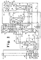
- Figure 2 is a schematic representation of another preferred embodiment of the invention wherein lower purity oxygen is withdrawn from the lower pressure column, passed into an auxiliary column and recovered from the auxiliary column, and wherein higher purity oxygen is also recovered from the auxiliary column.
- the invention comprises the providing of additional stripping vapor into the lower pressure column in the lower portion of the column.
- the additional stripping vapor originates from the lower portion of the higher pressure column and has a lower argon concentration relative to the stripping vapor generated by the lower pressure column bottom reboiler in a conventional double column system used to produce lower purity oxygen.
- the additional stripping vapor rises within the lower pressure column, and argon within this column preferentially passes into this rising vapor rather than passing down the column with the descending liquid and out of the column with the lower purity oxygen fluid.
- the resulting fluid which contains a substantial amount of nitrogen in addition to the argon, is further processed in a stripping column for nitrogen removal and the resulting argon-richer fluid is processed in an argon column to produce argon product.
- feed air 60 which has been cleaned of high boiling impurities such as carbon dioxide, water vapor and hydrocarbons and which has been compressed to a pressure generally within the range of from 4.48 to 5.17 bar (65 to 75 pounds per square inch absolute (psia)), is divided into first portion 61, comprising from about 20 to 30 percent of the feed air, and into second portion 64 comprising from about 70 to 80 percent of the feed air.
- First feed air portion 61 is cooled by indirect heat exchange with return streams in main heat exchanger 1.
- Resulting cooled first feed air portion 62 is at least partially condensed in bottom reboiler 23 by indirect heat exchange with boiling argon column 14 bottom liquid, and resulting fluid 62 is passed into first or higher pressure column 10 which is the higher pressure column of a double column which also comprises second or lower pressure column 12.
- Second feed air portion 64 is compressed to a pressure generally within the range of from 5.86 to 6.55 bar (85 to 95 psia) by passage through compressor 30, resulting compressed stream 65 is cooled of heat of compression by passage through cooler 40, and resulting stream 66 is cooled by indirect heat exchange with return streams in main heat exchanger 1.
- Resulting cooled feed air 67 is turboexpanded through turboexpander 31 to generate refrigeration and resulting feed air stream 68, at about the operating pressure of the higher pressure column 10 is passed into higher pressure column 10.
- Nitrogen-enriched vapor is passed in stream 81 from the upper portion of higher pressure column 10 into bottom reboiler 21 of lower pressure column 12 wherein it is condensed by indirect heat exchange with boiling lower pressure column 12 bottom liquid.
- Resulting nitrogen-enriched liquid 82 is divided into first portion 83 which is passed into the upper portion of higher pressure column 10 as reflux, and into second portion 84 which is subcooled by passage through subcooler 2 and passed as stream 85 into the upper portion of lower pressure column 12 as reflux.
- An additional nitrogen-enriched fluid stream 80 is passed from the upper portion of higher pressure column 10 into the upper portion of lower pressure column 12 as additional feed into lower pressure column 12.
- Oxygen-enriched liquid comprises generally from 35 to 45 mole percent oxygen and less than about 2 mole percent argon, with nitrogen comprising substantially all of the remainder.
- Oxygen-enriched liquid is withdrawn from the lower portion of higher pressure column 10 in stream 70 and subcooled by passage through subcooler 3.
- Resulting stream 71 is reduced in pressure by passage through valve 72 and resulting stream 73 is divided into first portion 74 and into second portion 75 which is passed into lower pressure column 12 as feed for the column.
- First oxygen-enriched liquid portion 74 is passed into argon column top condenser 24 which in this embodiment of the invention serves as the stripping vapor heat exchanger of the invention.
- top condenser 24 the oxygen-enriched liquid is vaporized by indirect heat exchange with argon column top vapor and resulting oxygen-enriched vapor 41, preferably along with any remaining unvaporized oxygen-enriched liquid 42, is passed in stream 43 into the lower portion of lower pressure column 12, preferably, as illustrated in Figure 1, at the level of bottom reboiler 21.
- the oxygen-enriched vapor provided into lower pressure column 12 in stream 43 provides additional upflowing vapor or stripping vapor into the column in addition to that generated by bottom reboiler 21.
- This additional stripping vapor has a lower argon concentration than the vapor generated by the bottom reboiler of a conventional lower purity oxygen process and thus serves to preferentially strip argon out of the downflowing liquid within the column.
- the introduction of the oxygen-enriched vapor, which contains a significant amount of nitrogen, at this lower point in the lower pressure column provides the additional benefit of decreasing the boiling temperature in the bottom reboiler which reduces the overall energy requirements for the system.
- stream 100 the feed for the argon column is taken from the upper portion of the lower pressure column rather than from the lower portion as in conventional practice.
- This stream is illustrated as stream 100 in Figure 1.
- a fluid comprising from about 8 to 20 mole percent argon, from about 60 to 82 mole percent nitrogen, with the remainder comprised substantially of oxygen, is withdrawn from the upper portion of lower pressure column 12 in stream 100 at a level generally from 15 to 40, preferably 15 to 25, equilibrium stages above the level at which additional stripping vapor in stream 43 is passed into the column.
- Stream 100 is passed into stripping column 13 wherein it undergoes cryogenic rectification to produce argon-enriched fluid and nitrogen top vapor.
- the nitrogen top vapor is passed in stream 101 from the upper portion of stripping column 13 into the upper portion of lower pressure column 12.
- Argon-enriched fluid which has an argon concentration which exceeds that of the argon-containing fluid in stream 100, is passed from the lower portion of stripping column 13 into argon column 14 in stream 102.
- a vapor stream 103 is passed from argon column 14 into the lower portion of stripping column 13 to serve as upflowing vapor for the stripping column.
- argon-enriched fluid is separated by cryogenic rectification in argon-richer fluid and oxygen-richer fluid.
- Argon richer fluid which has an argon concentration generally of at least 95 mole percent, is passed in vapor stream 90 into top condenser 24 wherein it is at least partially condensed by indirect heat exchange with the vaporizing oxygen-enriched liquid as was previously described. If desired, some of argon-richer stream 90 may be recovered as product argon either upstream or downstream of top condenser 24. In the embodiment of the invention illustrated in Figure 1, all of stream 90 is passed into top condenser 24 wherein it is completely condensed.
- Argon-richer liquid 91 from top condenser 24 is passed in part 93 into the upper portion of argon column 14 as reflux and recovered in part 92 as product argon.
- Oxygen-richer fluid is passed in stream 104 from the lower portion of argon column 14 into lower pressure column 12.
- Lower pressure column 12 is operating at a pressure less than that of higher pressure column 10 and generally within the range of from 1.24 to 1.52 bar (18 to 22 psia). Within lower pressure column 12 the various feeds are separated by cryogenic rectification into nitrogen-richer fluid and lower purity oxygen fluid. Nitrogen-richer fluid is withdrawn from the upper portion of lower pressure column 12 in stream 110, warmed by passage through heat exchangers 2, 3 and 1 and removed from the system in stream 112 which may be recovered in whole or in part as product nitrogen having a nitrogen concentration of 98 mole percent or more.
- Lower purity oxygen fluid is withdraw from the lower portion of lower pressure column 12 for recovery as product lower purity oxygen.
- the lower purity oxygen fluid withdrawn from lower pressure column 12 undergoes no further separation prior to recovery, i.e. it is recovered as product directly from the lower pressure column.
- lower purity oxygen fluid is withdrawn from the lower portion of lower pressure column 12 as vapor stream 113, warmed by passage through main heat exchanger 1 and recovered as product lower purity oxygen gas in stream 114.
- some of the lower purity oxygen fluid may be withdrawn from column 12 as liquid and recovered as product lower purity oxygen liquid.
- the lower purity oxygen fluid may be withdrawn from the lower portion of the lower pressure column as liquid, some may be recovered as liquid product lower purity oxygen and some or all of the withdrawn liquid may be pumped to a higher pressure, vaporized and recovered as high pressure lower purity oxygen gas product.
- compressed feed air portion 65 is not turboexpanded but rather is passed directly into higher pressure column 10 after passage through main heat exchanger 1.
- Cooled feed air portion 62 is turboexpanded by passage through turboexpander 44 and turboexpanded feed air stream 45 is warmed by partial traverse of main heat exchanger 1 and divided into three portions 46, 47 and 48.
- Portion 47 reboils the bottom of argon column 14 in the same manner as stream 62 in the embodiment illustrated in Figure 1.
- Resulting stream 49 is passed into higher pressure column 10.
- a portion 50 of stream 49 is subcooled by passage through subcooler 4 and then passed into the upper portion of lower pressure column 12.
- Feed air portion 48 is passed into bottom reboiler 51 of stripping column 13 wherein it is condensed to generate upflowing vapor for stripping column 13, thus removing the need to pass vapor from the argon column into the stripping column to serve as the upflowing vapor.
- Resulting condensed feed air portion 52 is passed into higher pressure column 10.
- stream 52 is combined with stream 49 and further processed as such.
- Nitrogen-richer vapor 110 is warmed by passage through heat exchanger 4 as well as heat exchangers 1, 2 and 3 prior to removal from the system.
- a portion 53 of oxygen-enriched vapor 43 is not passed into lower pressure column 12 but rather is passed into auxiliary column 11.
- Lower purity oxygen fluid is withdrawn from the lower portion of lower pressure column 12 as liquid stream 54 and passed into the upper portion of auxiliary column 11 wherein it is separated by cryogenic rectification into higher purity oxygen and lower purity oxygen having a lower oxygen concentration than the lower purity oxygen stream in 54.
- Auxiliary column 11 is operating at a pressure generally within the range of from 1.24 to 1.52 bar (18 to 22 psia) and is driven by feed air portion 46 which is condensed in auxiliary column bottom reboiler 55 to produce upflowing vapor for auxiliary column 11. Resulting condensed feed air 56 is passed into higher pressure column 10 for separation.
- Lower purity oxygen is withdrawn as stream 57 from the upper portion of auxiliary column 11, warmed by passage through main heat exchanger 1 and recovered as product lower purity oxygen 58.
- Top vapor taken from above the level where stream 57 is withdrawn from auxiliary column 11, is passed as stream 59 from auxiliary column 11 into the lower portion of lower pressure column 12.
- Higher purity oxygen fluid is withdrawn as liquid stream 76 from the lower portion of auxiliary column 11 for recovery as product higher purity oxygen.
- stream 76 may be pumped to a higher pressure by passage through liquid pump 77, vaporized by passage through main heat exchanger 1, and recovered as product high pressure higher purity oxygen gas 78.
Landscapes
- Engineering & Computer Science (AREA)
- Physics & Mathematics (AREA)
- Mechanical Engineering (AREA)
- Thermal Sciences (AREA)
- General Engineering & Computer Science (AREA)
- Health & Medical Sciences (AREA)
- Emergency Medicine (AREA)
- Separation By Low-Temperature Treatments (AREA)
- Organic Low-Molecular-Weight Compounds And Preparation Thereof (AREA)
- Oxygen, Ozone, And Oxides In General (AREA)
Claims (10)
- Verfahren zum Herstellen von Argon (92) und Sauerstoff(114; 58) niedrigerer Reinheit mittels Tieftemperaturrektifikation von Einsatzluft (60), wobei im Zuge des Verfahrens:(A) Einsatzluft (60) in eine bei höherem Druck arbeitenden Kolonne (10) einer Doppelkolonne eingeleitet wird, welche ferner eine bei niedrigerem Druck arbeitende Kolonne (12) umfasst, und mit Sauerstoff angereicherte Flüssigkeit mittels Tieftemperaturrektifikation innerhalb der bei höherem Druck arbeitenden Kolonne erzeugt wird;(B) mit Sauerstoff angereicherte Flüssigkeit (70) von der bei höherem Druck arbeitenden Kolonne (10) abgezogen wird, die abgezogene mit Sauerstoff angereicherte Flüssigkeit mindestens zum Teil verdampft wird, um mit Sauerstoff angereicherten Dampf (41, 43) zu erzeugen, und der mit Sauerstoff angereicherte Dampf in die bei niedrigerem Druck arbeitende Kolonne (12) auf dem Niveau eines Sumpfaufkochers (21) der bei niedrigerem Druck arbeitenden Kolonne eingeleitet wird;(C) Sauerstoff-Fluid niedrigerer Reinheit innerhalb der bei niedrigerem Druck arbeitenden Kolonne (12) erzeugt wird, ein Argon und Stickstoff aufweisendes Fluid (100) von dem oberen Abschnitt der bei niedrigerem Druck arbeitenden Kolonne abgezogen wird und dieses Fluid in eine Stripkolonne (13) eingeleitet wird;(D) mit Argon angereichertes Fluid in der Stripkolonne (13) erzeugt wird und mit Argon angereichertes Fluid (102) von der Stripkolonne in eine Argonkolonne (14) eingeleitet wird;(E) argonreicheres Fluid innerhalb der Argonkolonne (14) erzeugt wird und argonreicheres Fluid als Produktargon (92) gewonnen wird; und(F) Sauerstoff-Fluid mit niedrigerer Reinheit als Produktsauerstoff(114; 58) niedrigerer Reinheit gewonnen wird.
- Verfahren nach Anspruch 1, wobei Produktsauerstoff (114) niedrigerer Reinheit direkt von der bei niedrigem Druck arbeitenden Kolonne (12) gewonnen wird.
- Verfahren nach Anspruch 1, wobei Sauerstoff-Fluid (54) niedrigerer Reinheit von der bei niedrigerem Druck arbeitenden Kolonne (12) in eine Hilfskolonne (11) eingeleitet wird, in welcher es in Sauerstoff niedrigerer Reinheit und Sauerstoff höherer Reinheit zerlegt wird, und wobei Produktsauerstoff (57, 58) niedrigerer Reinheit von der Hilfskolonne gewonnen wird und Sauerstoff (76, 78) höherer Reinheit von der Hilfskolonne gewonnen wird.
- Verfahren nach Anspruch 3, wobei ferner mit Sauerstoff angereicherter Dampf (53) in die Hilfskolonne (11) eingeleitet wird.
- Verfahren nach Anspruch 1, wobei das argon- und stickstoffhaltige Fluid (100), welches von der bei niedrigerem Druck arbeitenden Kolonne (12) abgezogen wird, 15 bis 40 Gleichgewichtsstufen oberhalb des Niveaus abgezogen wird, wo mit Sauerstoff angereicherter Dampf (41, 43) in die bei niedrigerem Druck arbeitenden Kolonne eingeleitet wird.
- Vorrichtung zum Erzeugen von Argon (92) und Sauerstoff (114; 58) niedrigerer Reinheit mittels Tieftemperaturrektifikation von Einsatzluft (60) mit:(A) einer Doppelkolonne mit einer bei höherem Druck arbeitenden Kolonne (10) und einer bei niedrigerem Druck arbeitenden Kolonne (12) und Mitteln zum Einleiten von Einsatzluft (60) in die bei höherem Druck arbeitende Kolonne;(B) einem Stripdampfwärmetauscher (24), Mitteln zum Überleiten von mit Sauerstoff angereicherter Flüssigkeit (70) von dem unteren Abschnitt der bei höherem Druck arbeitenden Kolonne (10) in den Stripdampfwärmetauscher und Mitteln zum Überleiten von mit Sauerstoff angereichertem Dampf (41, 43) von dem Stripdampfwärmetauscher in die bei niedrigerem Druck arbeitende Kolonne (12) auf dem Niveau eines Sumpfaufkochers (21) der bei niedrigerem Druck arbeitenden Kolonne;(C) einer Stripkolonne (13) und Mitteln zum Überleiten eines argon- und stickstoffhaltigen Fluids (100) von dem oberen Abschnitt der bei niedrigerem Druck arbeitenden Kolonne (12) in die Stripkolonne;(D) einer Argonkolonne (14) und Mitteln zum Überleiten von mit Argon angereichertem Fluid (102) von dem unteren Abschnitt der Stripkolonne (13) in die Argonkolonne;(E) Mitteln zum Abziehen von argonreicherem Fluid von dem oberen Abschnitt der Argonkolonne (14) zwecks Gewinnung als Produktargon (92); und(F) Mitteln zum Abziehen von Sauerstoff-Fluid (113; 57) niedrigerer Reinheit von dem unteren Abschnitt der bei niedrigerem Druck arbeitenden Kolonne (12) zwecks Gewinnung als Sauerstoffprodukt (114; 58) niedrigerer Reinheit.
- Vorrichtung gemäß Anspruch 6, wobei die Mittel zum Abziehen von Sauerstoff-Fluid niedrigerer Reinheit von dem unteren Abschnitt der bei niedrigerem Druck arbeitenden Kolonne (12) zwecks Gewinnung als Produktsauerstoff (58) niedrigerer Reinheit eine Hilfskolonne (11), Mittel zum Überleiten von Sauerstoff-Fluid (54) niedrigerer Reinheit von dem unteren Abschnitt der bei niedrigerem Druck arbeitenden Kolonne in den oberen Abschnitt der Hilfskolonne sowie Mittel zum Gewinnen von Produktsauerstoff (57, 58) niedrigerer Reinheit von dem oberen Abschnitt der Hilfskolonne umfassen.
- Vorrichtung gemäß Anspruch 7, ferner versehen mit Mitteln zum Gewinnen von Sauerstoff (76, 78) höherer Reinheit von dem unteren Abschnitt der Hilfskolonne.
- Vorrichtung gemäß Anspruch 7, ferner versehen mit Mitteln zum Überleiten von mit Sauerstoff angereichertem Dampf (53) von dem Stripdampfwärmetauscher (24) in die Hilfskolonne (11).
- Vorrichtung gemäß Anspruch 6, wobei die Mittel zum Überleiten von argon- und stickstoffhaltigem Fluid (100) von dem oberen Abschnitt der bei niedrigerem Druck arbeitenden Kolonne (12) in die Stripkolonne (13) mit der bei niedrigerem Druck arbeitenden Kolonne auf einem Niveau 15 bis 40 Gleichgewichtsstufen über dem Niveau in Verbindung stehen, auf welchem die Mittel zum Einleiten von mit Sauerstoff angereichertem Dampf (41, 43) von dem Stripdampfwärmetauscher (24) in die bei niedrigerem Druck arbeitende Kolonne an einem Punkt unterhalb des Mittelpunkts der bei niedrigerem Druck arbeitenden Kolonne mit der Niederdruckkolonne in Verbindung stehen.
Applications Claiming Priority (2)
| Application Number | Priority Date | Filing Date | Title |
|---|---|---|---|
| US08/764,430 US5682765A (en) | 1996-12-12 | 1996-12-12 | Cryogenic rectification system for producing argon and lower purity oxygen |
| US764430 | 1996-12-12 |
Publications (3)
| Publication Number | Publication Date |
|---|---|
| EP0848219A2 EP0848219A2 (de) | 1998-06-17 |
| EP0848219A3 EP0848219A3 (de) | 1998-07-15 |
| EP0848219B1 true EP0848219B1 (de) | 2002-06-05 |
Family
ID=25070708
Family Applications (1)
| Application Number | Title | Priority Date | Filing Date |
|---|---|---|---|
| EP97113902A Expired - Lifetime EP0848219B1 (de) | 1996-12-12 | 1997-08-12 | Kryogenisches Rektifikationssystem zur Herstellung von Argon und Sauerstoff niedriger Reinheit |
Country Status (5)
| Country | Link |
|---|---|
| US (1) | US5682765A (de) |
| EP (1) | EP0848219B1 (de) |
| BR (1) | BR9704342A (de) |
| DE (1) | DE69713042T2 (de) |
| ES (1) | ES2174153T3 (de) |
Families Citing this family (6)
| Publication number | Priority date | Publication date | Assignee | Title |
|---|---|---|---|---|
| US5916261A (en) * | 1998-04-02 | 1999-06-29 | Praxair Technology, Inc. | Cryogenic argon production system with thermally integrated stripping column |
| US6227005B1 (en) * | 2000-03-01 | 2001-05-08 | Air Products And Chemicals, Inc. | Process for the production of oxygen and nitrogen |
| US9279613B2 (en) * | 2010-03-19 | 2016-03-08 | Praxair Technology, Inc. | Air separation method and apparatus |
| US20120036891A1 (en) * | 2010-08-12 | 2012-02-16 | Neil Mark Prosser | Air separation method and apparatus |
| CN108645118A (zh) * | 2018-06-07 | 2018-10-12 | 上海联风能源科技有限公司 | 一种提高氩气回收率的装置及方法 |
| WO2023061621A1 (de) * | 2021-10-12 | 2023-04-20 | Linde Gmbh | Verfahren zur tieftemperaturzerlegung von luft, verfahren zum betreiben eines stahlwerks und luftzerlegungsanlage |
Family Cites Families (14)
| Publication number | Priority date | Publication date | Assignee | Title |
|---|---|---|---|---|
| DE3722746A1 (de) * | 1987-07-09 | 1989-01-19 | Linde Ag | Verfahren und vorrichtung zur luftzerlegung durch rektifikation |
| US5315833A (en) * | 1991-10-15 | 1994-05-31 | Liquid Air Engineering Corporation | Process for the mixed production of high and low purity oxygen |
| US5305611A (en) * | 1992-10-23 | 1994-04-26 | Praxair Technology, Inc. | Cryogenic rectification system with thermally integrated argon column |
| DE4317916A1 (de) * | 1993-05-28 | 1994-12-01 | Linde Ag | Verfahren und Vorrichtung zur Gewinnung von Argon |
| US5425241A (en) * | 1994-05-10 | 1995-06-20 | Air Products And Chemicals, Inc. | Process for the cryogenic distillation of an air feed to produce an ultra-high purity oxygen product |
| GB9410686D0 (en) * | 1994-05-27 | 1994-07-13 | Boc Group Plc | Air separation |
| US5440884A (en) * | 1994-07-14 | 1995-08-15 | Praxair Technology, Inc. | Cryogenic air separation system with liquid air stripping |
| GB9414939D0 (en) * | 1994-07-25 | 1994-09-14 | Boc Group Plc | Air separation |
| US5490391A (en) * | 1994-08-25 | 1996-02-13 | The Boc Group, Inc. | Method and apparatus for producing oxygen |
| US5469710A (en) * | 1994-10-26 | 1995-11-28 | Praxair Technology, Inc. | Cryogenic rectification system with enhanced argon recovery |
| GB9500514D0 (en) * | 1995-01-11 | 1995-03-01 | Boc Group Plc | Air separation |
| US5528906A (en) * | 1995-06-26 | 1996-06-25 | The Boc Group, Inc. | Method and apparatus for producing ultra-high purity oxygen |
| GB9513765D0 (en) * | 1995-07-06 | 1995-09-06 | Boc Group Plc | Production of argon |
| US5546767A (en) * | 1995-09-29 | 1996-08-20 | Praxair Technology, Inc. | Cryogenic rectification system for producing dual purity oxygen |
-
1996
- 1996-12-12 US US08/764,430 patent/US5682765A/en not_active Expired - Lifetime
-
1997
- 1997-08-12 EP EP97113902A patent/EP0848219B1/de not_active Expired - Lifetime
- 1997-08-12 DE DE69713042T patent/DE69713042T2/de not_active Expired - Fee Related
- 1997-08-12 BR BR9704342A patent/BR9704342A/pt not_active IP Right Cessation
- 1997-08-12 ES ES97113902T patent/ES2174153T3/es not_active Expired - Lifetime
Also Published As
| Publication number | Publication date |
|---|---|
| US5682765A (en) | 1997-11-04 |
| BR9704342A (pt) | 1999-03-02 |
| EP0848219A2 (de) | 1998-06-17 |
| EP0848219A3 (de) | 1998-07-15 |
| DE69713042T2 (de) | 2003-02-06 |
| DE69713042D1 (de) | 2002-07-11 |
| ES2174153T3 (es) | 2002-11-01 |
Similar Documents
| Publication | Publication Date | Title |
|---|---|---|
| EP0841524B1 (de) | Kryogenisches Rektifiziersystem mit einer Sumpfflüssigkeitskolonne | |
| EP0692689A1 (de) | Kryogenisches Lufttrennungsverfahren mit Flüssigluftstripping | |
| EP0540900A1 (de) | Kryogenisches Rektifikationssystem zur Herstellung von ultrahochreinem Sauerstoff | |
| US5546767A (en) | Cryogenic rectification system for producing dual purity oxygen | |
| EP0594214B1 (de) | Kryogenisches Rektifikationsverfahren mit thermisch integrierter Argonkolonne | |
| US5765396A (en) | Cryogenic rectification system for producing high pressure nitrogen and high pressure oxygen | |
| US5678427A (en) | Cryogenic rectification system for producing low purity oxygen and high purity nitrogen | |
| US5628207A (en) | Cryogenic Rectification system for producing lower purity gaseous oxygen and high purity oxygen | |
| EP0823604A2 (de) | Kryogenisches Rektifikationssystem zur Herstellung von niedrigreinem Sauerstoff und hochreinem Sauerstoff | |
| EP1156291A1 (de) | Kryogenisches Luftzerlegungssystem mit aufgeteiltem Kocherrecycling | |
| US5682766A (en) | Cryogenic rectification system for producing lower purity oxygen and higher purity oxygen | |
| EP0936429B1 (de) | Kryogenisches Rektifikationsystem zur Herstellung von ultrahochreinem Stickstoff und ultrahochreinem Sauerstoff | |
| US5916262A (en) | Cryogenic rectification system for producing low purity oxygen and high purity oxygen | |
| EP0824209B1 (de) | Kryogenisches Rektifikationssystem mit Seitenkolonne zur Herstellung von Sauerstoff niedrigerer Reinheit und hochreinem Stickstoff | |
| US5596886A (en) | Cryogenic rectification system for producing gaseous oxygen and high purity nitrogen | |
| EP0848219B1 (de) | Kryogenisches Rektifikationssystem zur Herstellung von Argon und Sauerstoff niedriger Reinheit | |
| US6622520B1 (en) | Cryogenic rectification system for producing low purity oxygen using shelf vapor turboexpansion | |
| US5829271A (en) | Cryogenic rectification system for producing high pressure oxygen | |
| EP0959313B1 (de) | Kryogenisches Rektifikationssystem mit integriertem Phasentrenner mit Produktkocher | |
| US5878597A (en) | Cryogenic rectification system with serial liquid air feed | |
| US5873264A (en) | Cryogenic rectification system with intermediate third column reboil | |
| US5806342A (en) | Cryogenic rectification system for producing low purity oxygen and high purity oxygen |
Legal Events
| Date | Code | Title | Description |
|---|---|---|---|
| PUAI | Public reference made under article 153(3) epc to a published international application that has entered the european phase |
Free format text: ORIGINAL CODE: 0009012 |
|
| PUAL | Search report despatched |
Free format text: ORIGINAL CODE: 0009013 |
|
| AK | Designated contracting states |
Kind code of ref document: A2 Designated state(s): DE ES FR GB IT |
|
| AX | Request for extension of the european patent |
Free format text: AL;LT;LV;RO;SI |
|
| AK | Designated contracting states |
Kind code of ref document: A3 Designated state(s): AT BE CH DE DK ES FI FR GB GR IE IT LI LU MC NL PT SE |
|
| AX | Request for extension of the european patent |
Free format text: AL;LT;LV;RO;SI |
|
| 17P | Request for examination filed |
Effective date: 19980731 |
|
| AKX | Designation fees paid |
Free format text: DE ES FR GB IT |
|
| RBV | Designated contracting states (corrected) |
Designated state(s): DE ES FR GB IT |
|
| 17Q | First examination report despatched |
Effective date: 20000828 |
|
| GRAG | Despatch of communication of intention to grant |
Free format text: ORIGINAL CODE: EPIDOS AGRA |
|
| GRAG | Despatch of communication of intention to grant |
Free format text: ORIGINAL CODE: EPIDOS AGRA |
|
| GRAH | Despatch of communication of intention to grant a patent |
Free format text: ORIGINAL CODE: EPIDOS IGRA |
|
| GRAH | Despatch of communication of intention to grant a patent |
Free format text: ORIGINAL CODE: EPIDOS IGRA |
|
| GRAA | (expected) grant |
Free format text: ORIGINAL CODE: 0009210 |
|
| AK | Designated contracting states |
Kind code of ref document: B1 Designated state(s): DE ES FR GB IT |
|
| REG | Reference to a national code |
Ref country code: GB Ref legal event code: FG4D |
|
| REF | Corresponds to: |
Ref document number: 69713042 Country of ref document: DE Date of ref document: 20020711 |
|
| ET | Fr: translation filed | ||
| REG | Reference to a national code |
Ref country code: ES Ref legal event code: FG2A Ref document number: 2174153 Country of ref document: ES Kind code of ref document: T3 |
|
| PLBE | No opposition filed within time limit |
Free format text: ORIGINAL CODE: 0009261 |
|
| STAA | Information on the status of an ep patent application or granted ep patent |
Free format text: STATUS: NO OPPOSITION FILED WITHIN TIME LIMIT |
|
| 26N | No opposition filed |
Effective date: 20030306 |
|
| PGFP | Annual fee paid to national office [announced via postgrant information from national office to epo] |
Ref country code: ES Payment date: 20040907 Year of fee payment: 8 |
|
| PGFP | Annual fee paid to national office [announced via postgrant information from national office to epo] |
Ref country code: GB Payment date: 20050804 Year of fee payment: 9 |
|
| PG25 | Lapsed in a contracting state [announced via postgrant information from national office to epo] |
Ref country code: IT Free format text: LAPSE BECAUSE OF NON-PAYMENT OF DUE FEES;WARNING: LAPSES OF ITALIAN PATENTS WITH EFFECTIVE DATE BEFORE 2007 MAY HAVE OCCURRED AT ANY TIME BEFORE 2007. THE CORRECT EFFECTIVE DATE MAY BE DIFFERENT FROM THE ONE RECORDED. Effective date: 20050812 |
|
| PG25 | Lapsed in a contracting state [announced via postgrant information from national office to epo] |
Ref country code: ES Free format text: LAPSE BECAUSE OF NON-PAYMENT OF DUE FEES Effective date: 20050813 |
|
| PGFP | Annual fee paid to national office [announced via postgrant information from national office to epo] |
Ref country code: FR Payment date: 20050817 Year of fee payment: 9 |
|
| PGFP | Annual fee paid to national office [announced via postgrant information from national office to epo] |
Ref country code: DE Payment date: 20050930 Year of fee payment: 9 |
|
| REG | Reference to a national code |
Ref country code: ES Ref legal event code: FD2A Effective date: 20050813 |
|
| PG25 | Lapsed in a contracting state [announced via postgrant information from national office to epo] |
Ref country code: DE Free format text: LAPSE BECAUSE OF NON-PAYMENT OF DUE FEES Effective date: 20070301 |
|
| GBPC | Gb: european patent ceased through non-payment of renewal fee |
Effective date: 20060812 |
|
| REG | Reference to a national code |
Ref country code: FR Ref legal event code: ST Effective date: 20070430 |
|
| PG25 | Lapsed in a contracting state [announced via postgrant information from national office to epo] |
Ref country code: GB Free format text: LAPSE BECAUSE OF NON-PAYMENT OF DUE FEES Effective date: 20060812 |
|
| PG25 | Lapsed in a contracting state [announced via postgrant information from national office to epo] |
Ref country code: FR Free format text: LAPSE BECAUSE OF NON-PAYMENT OF DUE FEES Effective date: 20060831 |