EP0847892B1 - Vehicle seat position detection system - Google Patents
Vehicle seat position detection system Download PDFInfo
- Publication number
- EP0847892B1 EP0847892B1 EP97203580A EP97203580A EP0847892B1 EP 0847892 B1 EP0847892 B1 EP 0847892B1 EP 97203580 A EP97203580 A EP 97203580A EP 97203580 A EP97203580 A EP 97203580A EP 0847892 B1 EP0847892 B1 EP 0847892B1
- Authority
- EP
- European Patent Office
- Prior art keywords
- seat
- vehicle seat
- mounting rails
- rails
- switch
- Prior art date
- Legal status (The legal status is an assumption and is not a legal conclusion. Google has not performed a legal analysis and makes no representation as to the accuracy of the status listed.)
- Expired - Lifetime
Links
- 238000001514 detection method Methods 0.000 title claims description 33
- 238000012544 monitoring process Methods 0.000 claims description 13
- 239000004020 conductor Substances 0.000 claims description 6
- 230000002301 combined effect Effects 0.000 description 1
- 238000010586 diagram Methods 0.000 description 1
Images



Classifications
-
- B—PERFORMING OPERATIONS; TRANSPORTING
- B60—VEHICLES IN GENERAL
- B60N—SEATS SPECIALLY ADAPTED FOR VEHICLES; VEHICLE PASSENGER ACCOMMODATION NOT OTHERWISE PROVIDED FOR
- B60N2/00—Seats specially adapted for vehicles; Arrangement or mounting of seats in vehicles
- B60N2/02—Seats specially adapted for vehicles; Arrangement or mounting of seats in vehicles the seat or part thereof being movable, e.g. adjustable
- B60N2/04—Seats specially adapted for vehicles; Arrangement or mounting of seats in vehicles the seat or part thereof being movable, e.g. adjustable the whole seat being movable
- B60N2/06—Seats specially adapted for vehicles; Arrangement or mounting of seats in vehicles the seat or part thereof being movable, e.g. adjustable the whole seat being movable slidable
-
- B—PERFORMING OPERATIONS; TRANSPORTING
- B60—VEHICLES IN GENERAL
- B60N—SEATS SPECIALLY ADAPTED FOR VEHICLES; VEHICLE PASSENGER ACCOMMODATION NOT OTHERWISE PROVIDED FOR
- B60N2/00—Seats specially adapted for vehicles; Arrangement or mounting of seats in vehicles
- B60N2/02—Seats specially adapted for vehicles; Arrangement or mounting of seats in vehicles the seat or part thereof being movable, e.g. adjustable
- B60N2/0224—Non-manual adjustments, e.g. with electrical operation
- B60N2/0244—Non-manual adjustments, e.g. with electrical operation with logic circuits
- B60N2/0272—Non-manual adjustments, e.g. with electrical operation with logic circuits using sensors or detectors for detecting the position of seat parts
Definitions
- the present invention relates to a vehicle seat position detection system in accordance with the preamble, disclosed for example in document DE 3803602 A, of the independent claim 1.
- Motor vehicles are being designed in such a way that certain seats within the vehicle can be moved from one location to another. This is particularly so in multi-purpose vehicles (MPVs) which are capable of carrying a large number of occupants.
- MPVs multi-purpose vehicles
- the rear seats that is, the seats behind the front seats of the vehicle
- the rear seats can be removed, or moved to different locations.
- electrically operated devices and sensors associated with a vehicle seat such as air bags, seat belt tensioners, seat belt locking sensors, etc.
- the aim of the present invention is to provide a system which can identify the location of a vehicle seat in one of a number of possible locations.
- a vehicle seat position detection system in accordance with the present invention as defined in claim 1 comprises a pair of mounting rails securable to a floor of a motor vehicle, the rails being spaced apart and extending substantially parallel to one another; a seat detection switch associated with at least one of the mounting rails, the switch being normally open but being moved to a closed position when a vehicle seat is secured to the mounting rails; and a monitoring circuit connected to the seat detection switch to monitor the status of the switch.
- the present invention provides a system by which the location of a vehicle seat can be determined.
- FIG. 1 to 4 an outline of a motor vehicle 10 is shown which has a vehicle body 12 with a front 14 and a rear 16.
- the vehicle body 12 comprises a floor 18 on which are secured eight mounting rails 20-34.
- the mounting rails 20-34 lie along axes which are substantially parallel to each other, and substantially parallel to a centre line extending between the front 14 and the rear 16 of the motor vehicle 10.
- a predetermined spacing exists between the pair of rails 20 and 24, between the pair of rails 22 and 26, between the pair of rails 26 and 28, between the pair of rails 28 and 32, and between the pair of rails 30 and 34.
- the spacing between each pair of rails is such that a vehicle seat (not shown) can be secured to any of each pair of rails.
- a vehicle seat can be position in any one of eleven different positions, as indicated by the dashed outlines 36-56, and that up to five vehicle seats may be secured to the rails 20-34. With such an arrangement, or a similar arrangement, it is necessary to know if a vehicle seat is secured to any pair of rails 20-34, and the actual location of the vehicle seat.
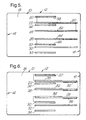
- a seat detection switch 58-66 ( Figure 5) is associated with at least one rail of each pair of rails.
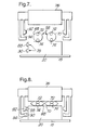
- each seat detection switch 58-66 comprises a pair of flexible tubes 68,70 ( Figures 7 and 8) which are mounted on top of the respective rail 20-30 of each pair of rails.
- Each tube 68,70 has a pair of longitudinally extending flexible electrical conductors 72,74 which are normally spaced apart ( Figure 7).
- a portion 76 of the seat engages and compresses the tubes 68,70 to bring the electrical conductors 72,74 into contact with one another ( Figure 8).
- connection of the electrical conductors 72,74 to a suitable monitoring circuit 96 will provide an indication of the presence of a vehicle seat and its location as a result of the electrical shorting of the conductors.
- a suitable monitoring circuit 96 (described below) will provide an indication of the presence of a vehicle seat and its location as a result of the electrical shorting of the conductors.
- only five pairs of flexible tubes 68,70 are required to provide an indication of vehicle seat presence and location in the positions 36-56.
- Other forms of seat detection switch may be used such as a single flexible tube (as described above) associated with at least one rail 20-34 of each pair of rails, or push-button switches, or any other suitable type of switch which is actuable when a seat is secured to a pair of rails 20-34.
- pairs 78-86 of electrical connector rails 88,90 are mounted on one side of the associated rail 20-34 ( Figures 7 and 8).
- electrical connectors 92,94 associated with the vehicle seat make an electrical connection with a respective connector rail 88,90 ( Figures 7 and 8).
- the electrical connectors 92,94 associated with each vehicle seat are connected to electrically operated devices and sensors associated with the seat, such as air bags, seat belt tensioners, seat belt locking sensors, etc.
- the connector rails 88,90 are also connected with the monitoring circuit 96 associated with the seat detection switches 58-66, so that on securing a vehicle seat to a pair of rails 20-34, the monitoring circuit can also monitor and control the operation of the electrically operated devices and sensors associated with that seat.
- the pairs 78-86 of connector rails 88,90 may be connected to a separate control circuit (not shown) which also receives signals from the monitoring circuit 94, the control circuit controlling the operation of the electrically operated devices and sensors associated with that seat.
- only five pairs of connector rails 88,90 are required to provide electrical connections to a vehicle seat located in any one of the positions 36-56.
- Other forms of electrical connection may be associated with the rails 20-34 to provide electrical connection to the devices and sensors associated with a vehicle seat.
- the monitoring circuit 96 comprises a microcomputer 102 with an associated digital to analogue converter 100 which receives voltage signals from a junction 98.
- the junction 98 is connected to a voltage source V cc by way of a resistor R 0 .
- the junction 98 is also connected to each seat detection switch 58-66 by way of a resistor R 1 -R 5 respectively.
- R 1 to R 5 By choosing the values of R 1 to R 5 accordingly, it is possible to provide a value for R s which has a different value for each combination of vehicle seats present in the motor vehicle 10.
- the arrangement of the mounting rails 20-34 may be different from one vehicle to another, and the present invention is such that the vehicle seat position detection system can be used with other layouts for the mounting rails.
- the monitoring circuit may be such that it monitors the status of each seat detection switch on an individual basis, and either activates the relevant electrically operated devices and sensors associated with each seat that is present, or sends a signal to a separate control circuit to activate the electrically operated devices and sensors associated with each seat.
Landscapes
- Engineering & Computer Science (AREA)
- Aviation & Aerospace Engineering (AREA)
- Transportation (AREA)
- Mechanical Engineering (AREA)
- Seats For Vehicles (AREA)
Description
- The present invention relates to a vehicle seat position detection system in accordance with the preamble, disclosed for example in document DE 3803602 A, of the independent claim 1.
- Motor vehicles are being designed in such a way that certain seats within the vehicle can be moved from one location to another. This is particularly so in multi-purpose vehicles (MPVs) which are capable of carrying a large number of occupants. In such vehicles, the rear seats (that is, the seats behind the front seats of the vehicle) can be removed, or moved to different locations. With the use of electrically operated devices and sensors associated with a vehicle seat (such as air bags, seat belt tensioners, seat belt locking sensors, etc.) it is a requirement that the exact location of a seat is known.
- The aim of the present invention is to provide a system which can identify the location of a vehicle seat in one of a number of possible locations.
- A vehicle seat position detection system in accordance with the present invention as defined in claim 1 comprises a pair of mounting rails securable to a floor of a motor vehicle, the rails being spaced apart and extending substantially parallel to one another; a seat detection switch associated with at least one of the mounting rails, the switch being normally open but being moved to a closed position when a vehicle seat is secured to the mounting rails; and a monitoring circuit connected to the seat detection switch to monitor the status of the switch.
- The present invention provides a system by which the location of a vehicle seat can be determined.
- The present invention will now be described, by way of example, with reference to the accompanying drawings, in which:-
- Figure 1 is a schematic layout of seat mounting rails within a vehicle showing five potential seat positions in which a vehicle seat position detection system in accordance with the present invention is used;
- Figure 2 is the schematic layout shown in Figure 1 showing three further potential seat positions;
- Figure 3 is the schematic layout shown in Figure 1 showing two further potential seat positions;
- Figure 4 is the schematic layout shown in Figure 1 showing one further potential seat position;
- Figure 5 is the schematic layout shown in Figure 1 showing the layout for the seat detection switches for the vehicle seat position detection system of Figure 1;
- Figure 6 is the schematic layout shown in Figure 1 showing the layout for the electrical connections for the vehicle seat position detection system of Figure 1;
- Figure 7 is a front view, shown schematically, of the seat detection switches and electrical connections of Figures 5 and 6 prior to the mounting of a seat on the seat mounting rails;
- Figure 8 is a front view, shown schematically, of the seat detection switches and electrical connections of Figures 5 and 6 after the mounting of a seat on the seat mounting rails; and
- Figure 9 is a circuit diagram of the monitoring circuit and seat detection switches of the vehicle seat position detection system of Figure 1.
-
- Referring to Figures 1 to 4, an outline of a
motor vehicle 10 is shown which has avehicle body 12 with afront 14 and a rear 16. Thevehicle body 12 comprises afloor 18 on which are secured eight mounting rails 20-34. The mounting rails 20-34 lie along axes which are substantially parallel to each other, and substantially parallel to a centre line extending between thefront 14 and the rear 16 of themotor vehicle 10. A predetermined spacing exists between the pair ofrails rails rails rails rails - In the present invention, a seat detection switch 58-66 (Figure 5) is associated with at least one rail of each pair of rails. In the preferred embodiment, each seat detection switch 58-66 comprises a pair of
flexible tubes 68,70 (Figures 7 and 8) which are mounted on top of the respective rail 20-30 of each pair of rails. Eachtube electrical conductors portion 76 of the seat engages and compresses thetubes electrical conductors electrical conductors flexible tubes - Also associated with at least one rail of each pair of rails 20-34 are pairs 78-86 of
electrical connector rails 88,90 (Figures 6 and 7). In the preferred embodiment, theconnector rails electrical connectors respective connector rail 88,90 (Figures 7 and 8). Theelectrical connectors connector rails monitoring circuit 96 associated with the seat detection switches 58-66, so that on securing a vehicle seat to a pair of rails 20-34, the monitoring circuit can also monitor and control the operation of the electrically operated devices and sensors associated with that seat. Alternatively, the pairs 78-86 ofconnector rails monitoring circuit 94, the control circuit controlling the operation of the electrically operated devices and sensors associated with that seat. In the present arrangement, only five pairs ofconnector rails - Referring to Figure 9, the
monitoring circuit 96 comprises amicrocomputer 102 with an associated digital toanalogue converter 100 which receives voltage signals from ajunction 98. Thejunction 98 is connected to a voltage source Vcc by way of a resistor R0. Thejunction 98 is also connected to each seat detection switch 58-66 by way of a resistor R1-R5 respectively. The combined effect Rs of the resistors R1-R5 atjunction 98 is defined bymotor vehicle 10. The value of Rs provides a voltage signal Vin at the converter 100microcomputer 102 to determine the seat configuration present in the motor vehicle. From this determination, the microcomputer can either activate the relevant the electrically operated devices and sensors associated with each seat that is present, or send a signal to a separate control circuit to activate the electrically operated devices and sensors associated with each seat. - The arrangement of the mounting rails 20-34 may be different from one vehicle to another, and the present invention is such that the vehicle seat position detection system can be used with other layouts for the mounting rails. Also, as an alternative, the monitoring circuit may be such that it monitors the status of each seat detection switch on an individual basis, and either activates the relevant electrically operated devices and sensors associated with each seat that is present, or sends a signal to a separate control circuit to activate the electrically operated devices and sensors associated with each seat.
Claims (5)
- A vehicle seat position detection system comprising at least a pair of mounting rails (20-34) securable to a floor (18) of a motor vehicle (10), the rails being spaced apart and extending substantially parallel to one another; and a seat detection switch (58-66) associated with at least one of the mounting rails of each pair, characterised in that each switch is adapted to detect the presence of a vehicle seat on the mounting rails, each switch being normally open but being moved to a closed position when a vehicle seat is secured to the mounting rails; and in that a monitoring circuit (96) for monitoring the location of a seat is connected to each of the seat detection switches to monitor the status of each switch.
- A vehicle seat position detection system as claimed in Claim 1, wherein the seat detection switch (58-66) comprises a flexible tube (68,70) with a pair of electrical conductors (72,74) mounted internally thereof, the conductors being normally diametrically spaced when a vehicle seat is not secured to the mounting rails (20-34).
- A vehicle seat position detection system as claimed in Claim 1 or Claim 2, wherein at least one electrical connector rail (88,90) is associated with at least one of the mounting rails (20-34) for providing an electrical connection with a corresponding electrical connector (92,94) on a vehicle seat when secured to the mounting rails.
- A vehicle seat position detection system as claimed in any one of Claims 1 to 3, wherein the monitoring circuit (96) comprises a resistor (R1-R5) connected in series with the seat detection switch (58-66); a resistor (R0) connected to a voltage source (Vcc) and to the resistor connected to the seat detection switch (R1-R5); and a microcomputer (102) connected to the junction (98) between the two resistors and monitoring the voltage at junction.
- A vehicle seat position detection system as claimed in any one of Claims 1 to 4 comprising at least two pairs of mounting rails (20-34), and a seat detection switch (58-66) associated with each pair of mounting rails, wherein the monitoring circuit 96 is connected to each seat detection switch to monitor the status of each switch.
Applications Claiming Priority (2)
| Application Number | Priority Date | Filing Date | Title |
|---|---|---|---|
| GB9625852A GB2320330B (en) | 1996-12-12 | 1996-12-12 | Vehicle seat position detection system |
| GB9625852 | 1996-12-12 |
Publications (3)
| Publication Number | Publication Date |
|---|---|
| EP0847892A2 EP0847892A2 (en) | 1998-06-17 |
| EP0847892A3 EP0847892A3 (en) | 1999-01-27 |
| EP0847892B1 true EP0847892B1 (en) | 2002-03-27 |
Family
ID=10804350
Family Applications (1)
| Application Number | Title | Priority Date | Filing Date |
|---|---|---|---|
| EP97203580A Expired - Lifetime EP0847892B1 (en) | 1996-12-12 | 1997-11-17 | Vehicle seat position detection system |
Country Status (3)
| Country | Link |
|---|---|
| EP (1) | EP0847892B1 (en) |
| DE (1) | DE69711347T2 (en) |
| GB (1) | GB2320330B (en) |
Families Citing this family (2)
| Publication number | Priority date | Publication date | Assignee | Title |
|---|---|---|---|---|
| FR2868741B1 (en) | 2004-04-08 | 2008-02-08 | Faurecia Sieges Automobile | SYSTEM FOR DETERMINING THE LOCATION AND ORIENTATION OF A REMOVABLE AND / OR ADJUSTABLE SEAT IN POSITION IN A MOTOR VEHICLE |
| DE102019215985A1 (en) * | 2019-10-17 | 2021-04-22 | Volkswagen Aktiengesellschaft | Vehicle console system and motor vehicle |
Family Cites Families (3)
| Publication number | Priority date | Publication date | Assignee | Title |
|---|---|---|---|---|
| JPS63196756U (en) * | 1987-06-09 | 1988-12-19 | ||
| DE3803602A1 (en) * | 1988-02-06 | 1989-08-17 | Alfred Weber | Adjusting device for a seat which is guided in a longitudinally displaceable manner and is provided with a releasable catch in an in-use position |
| FR2702717B1 (en) * | 1993-03-19 | 1995-05-24 | Matra Automobile | Seat position adjustment device for a motor vehicle and seat usable with such a device. |
-
1996
- 1996-12-12 GB GB9625852A patent/GB2320330B/en not_active Expired - Fee Related
-
1997
- 1997-11-17 EP EP97203580A patent/EP0847892B1/en not_active Expired - Lifetime
- 1997-11-17 DE DE69711347T patent/DE69711347T2/en not_active Expired - Lifetime
Also Published As
| Publication number | Publication date |
|---|---|
| DE69711347D1 (en) | 2002-05-02 |
| DE69711347T2 (en) | 2002-11-07 |
| GB9625852D0 (en) | 1997-01-29 |
| EP0847892A3 (en) | 1999-01-27 |
| EP0847892A2 (en) | 1998-06-17 |
| GB2320330A (en) | 1998-06-17 |
| GB2320330B (en) | 2000-10-18 |
Similar Documents
| Publication | Publication Date | Title |
|---|---|---|
| US7796017B2 (en) | Capacitance type seat occupant sensor system | |
| EP1533193B1 (en) | Occupant detection system | |
| US5544914A (en) | Air bag disabler control circuit | |
| EP0802093B1 (en) | Safety device for a vehicle with a removable seat, in particular passenger seat | |
| KR100491187B1 (en) | Vehicle Passenger Detection System and Method | |
| US8378819B2 (en) | Electrostatic occupant detection apparatus and method for detecting failure of the same | |
| US4614876A (en) | Vehicle passenger restraint system | |
| JPH104632A (en) | Vehicle power supply device and centralized wiring device | |
| JPH08239008A (en) | Electronic equipment | |
| US7917263B2 (en) | Activation system and method for passenger protection device | |
| US6040637A (en) | Selector switch circuit for disabling an airbag | |
| US7032700B2 (en) | Occupant weight detecting device | |
| JP2000127848A (en) | Direction indicating device provided in a vehicle towing a trailer and a trailer connection determination circuit used in the direction indicating device | |
| EP0957013A2 (en) | Ignition control system for a passive safety device with interconnected airbag control and roll-over control | |
| EP0847892A2 (en) | Vehicle seat position detection system | |
| US6236920B1 (en) | Distributed vehicle safety with bus connection components having a remotely-located initiation electronics arrangement and a bus tap arrangement | |
| JP3353817B2 (en) | Occupant detection system | |
| EP0781219B1 (en) | System for triggering a protecting device | |
| JPH10319133A (en) | Crew detection system | |
| KR100476570B1 (en) | Device for controlling electronic airbag of frame body car | |
| JP2004248403A (en) | Ground detection mechanism for automotive power supply | |
| JP3851388B2 (en) | Airbag deployment control device and switch circuit | |
| EP0890488A2 (en) | A system for controlling the activation of an air-bag in a motor-vehicle | |
| JP3378069B2 (en) | Switch circuit for ignition element of vehicle safety device and control device for vehicle safety device | |
| JPH0635832Y2 (en) | Squib circuit for airbag device |
Legal Events
| Date | Code | Title | Description |
|---|---|---|---|
| PUAI | Public reference made under article 153(3) epc to a published international application that has entered the european phase |
Free format text: ORIGINAL CODE: 0009012 |
|
| AK | Designated contracting states |
Kind code of ref document: A2 Designated state(s): DE ES FR IT |
|
| AX | Request for extension of the european patent |
Free format text: AL;LT;LV;MK;RO;SI |
|
| PUAL | Search report despatched |
Free format text: ORIGINAL CODE: 0009013 |
|
| AK | Designated contracting states |
Kind code of ref document: A3 Designated state(s): AT BE CH DE DK ES FI FR GB GR IE IT LI LU MC NL PT SE |
|
| AX | Request for extension of the european patent |
Free format text: AL;LT;LV;MK;RO;SI |
|
| 17P | Request for examination filed |
Effective date: 19990727 |
|
| AKX | Designation fees paid |
Free format text: DE ES FR IT |
|
| GRAG | Despatch of communication of intention to grant |
Free format text: ORIGINAL CODE: EPIDOS AGRA |
|
| 17Q | First examination report despatched |
Effective date: 20010605 |
|
| GRAG | Despatch of communication of intention to grant |
Free format text: ORIGINAL CODE: EPIDOS AGRA |
|
| GRAH | Despatch of communication of intention to grant a patent |
Free format text: ORIGINAL CODE: EPIDOS IGRA |
|
| GRAH | Despatch of communication of intention to grant a patent |
Free format text: ORIGINAL CODE: EPIDOS IGRA |
|
| GRAA | (expected) grant |
Free format text: ORIGINAL CODE: 0009210 |
|
| AK | Designated contracting states |
Kind code of ref document: B1 Designated state(s): DE ES FR IT |
|
| REF | Corresponds to: |
Ref document number: 69711347 Country of ref document: DE Date of ref document: 20020502 |
|
| ET | Fr: translation filed | ||
| PG25 | Lapsed in a contracting state [announced via postgrant information from national office to epo] |
Ref country code: ES Free format text: LAPSE BECAUSE OF FAILURE TO SUBMIT A TRANSLATION OF THE DESCRIPTION OR TO PAY THE FEE WITHIN THE PRESCRIBED TIME-LIMIT Effective date: 20020925 |
|
| PLBE | No opposition filed within time limit |
Free format text: ORIGINAL CODE: 0009261 |
|
| STAA | Information on the status of an ep patent application or granted ep patent |
Free format text: STATUS: NO OPPOSITION FILED WITHIN TIME LIMIT |
|
| 26N | No opposition filed |
Effective date: 20021230 |
|
| REG | Reference to a national code |
Ref country code: FR Ref legal event code: TP |
|
| PGFP | Annual fee paid to national office [announced via postgrant information from national office to epo] |
Ref country code: DE Payment date: 20091112 Year of fee payment: 13 |
|
| PGFP | Annual fee paid to national office [announced via postgrant information from national office to epo] |
Ref country code: IT Payment date: 20091116 Year of fee payment: 13 Ref country code: FR Payment date: 20091123 Year of fee payment: 13 |
|
| REG | Reference to a national code |
Ref country code: FR Ref legal event code: ST Effective date: 20110801 |
|
| REG | Reference to a national code |
Ref country code: DE Ref legal event code: R119 Ref document number: 69711347 Country of ref document: DE Effective date: 20110601 Ref country code: DE Ref legal event code: R119 Ref document number: 69711347 Country of ref document: DE Effective date: 20110531 |
|
| PG25 | Lapsed in a contracting state [announced via postgrant information from national office to epo] |
Ref country code: DE Free format text: LAPSE BECAUSE OF NON-PAYMENT OF DUE FEES Effective date: 20110531 |
|
| PG25 | Lapsed in a contracting state [announced via postgrant information from national office to epo] |
Ref country code: FR Free format text: LAPSE BECAUSE OF NON-PAYMENT OF DUE FEES Effective date: 20101130 |
|
| PG25 | Lapsed in a contracting state [announced via postgrant information from national office to epo] |
Ref country code: IT Free format text: LAPSE BECAUSE OF NON-PAYMENT OF DUE FEES Effective date: 20101117 |