EP0847372B1 - Hydrogen cyanide process and apparatus therefor - Google Patents
Hydrogen cyanide process and apparatus therefor Download PDFInfo
- Publication number
- EP0847372B1 EP0847372B1 EP96929384A EP96929384A EP0847372B1 EP 0847372 B1 EP0847372 B1 EP 0847372B1 EP 96929384 A EP96929384 A EP 96929384A EP 96929384 A EP96929384 A EP 96929384A EP 0847372 B1 EP0847372 B1 EP 0847372B1
- Authority
- EP
- European Patent Office
- Prior art keywords
- stream
- oxidant
- mixed
- conduit
- mixing
- Prior art date
- Legal status (The legal status is an assumption and is not a legal conclusion. Google has not performed a legal analysis and makes no representation as to the accuracy of the status listed.)
- Expired - Lifetime
Links
- LELOWRISYMNNSU-UHFFFAOYSA-N hydrogen cyanide Chemical compound N#C LELOWRISYMNNSU-UHFFFAOYSA-N 0.000 title claims abstract description 53
- 238000000034 method Methods 0.000 title claims abstract description 26
- VNWKTOKETHGBQD-UHFFFAOYSA-N methane Chemical compound C VNWKTOKETHGBQD-UHFFFAOYSA-N 0.000 claims abstract description 56
- QGZKDVFQNNGYKY-UHFFFAOYSA-N Ammonia Chemical compound N QGZKDVFQNNGYKY-UHFFFAOYSA-N 0.000 claims abstract description 54
- 239000007800 oxidant agent Substances 0.000 claims abstract description 44
- 230000001590 oxidative effect Effects 0.000 claims abstract description 44
- 229910021529 ammonia Inorganic materials 0.000 claims abstract description 27
- 239000003054 catalyst Substances 0.000 claims abstract description 24
- QVGXLLKOCUKJST-UHFFFAOYSA-N atomic oxygen Chemical compound [O] QVGXLLKOCUKJST-UHFFFAOYSA-N 0.000 claims abstract description 21
- 239000001301 oxygen Substances 0.000 claims abstract description 21
- 229910052760 oxygen Inorganic materials 0.000 claims abstract description 21
- 238000005474 detonation Methods 0.000 claims abstract description 9
- 230000015572 biosynthetic process Effects 0.000 claims abstract description 8
- UFHFLCQGNIYNRP-UHFFFAOYSA-N Hydrogen Chemical compound [H][H] UFHFLCQGNIYNRP-UHFFFAOYSA-N 0.000 claims abstract description 6
- 239000001257 hydrogen Substances 0.000 claims abstract description 6
- 229910052739 hydrogen Inorganic materials 0.000 claims abstract description 6
- 238000004519 manufacturing process Methods 0.000 claims abstract description 5
- 230000003197 catalytic effect Effects 0.000 claims abstract description 3
- 238000004200 deflagration Methods 0.000 claims description 15
- 238000006243 chemical reaction Methods 0.000 claims description 12
- 239000000203 mixture Substances 0.000 claims description 10
- 230000001737 promoting effect Effects 0.000 claims description 3
- 230000002401 inhibitory effect Effects 0.000 claims description 2
- 238000006189 Andrussov oxidation reaction Methods 0.000 abstract description 5
- IJGRMHOSHXDMSA-UHFFFAOYSA-N Atomic nitrogen Chemical compound N#N IJGRMHOSHXDMSA-UHFFFAOYSA-N 0.000 description 12
- 229910052757 nitrogen Inorganic materials 0.000 description 6
- 238000010276 construction Methods 0.000 description 3
- 239000007789 gas Substances 0.000 description 3
- 229910052751 metal Inorganic materials 0.000 description 3
- 239000002184 metal Substances 0.000 description 3
- CURLTUGMZLYLDI-UHFFFAOYSA-N Carbon dioxide Chemical compound O=C=O CURLTUGMZLYLDI-UHFFFAOYSA-N 0.000 description 2
- 239000000463 material Substances 0.000 description 2
- 239000000376 reactant Substances 0.000 description 2
- 239000011541 reaction mixture Substances 0.000 description 2
- 238000000926 separation method Methods 0.000 description 2
- 230000002459 sustained effect Effects 0.000 description 2
- XLYOFNOQVPJJNP-UHFFFAOYSA-N water Substances O XLYOFNOQVPJJNP-UHFFFAOYSA-N 0.000 description 2
- UGFAIRIUMAVXCW-UHFFFAOYSA-N Carbon monoxide Chemical compound [O+]#[C-] UGFAIRIUMAVXCW-UHFFFAOYSA-N 0.000 description 1
- 239000006227 byproduct Substances 0.000 description 1
- 229910002092 carbon dioxide Inorganic materials 0.000 description 1
- 239000001569 carbon dioxide Substances 0.000 description 1
- 229910002091 carbon monoxide Inorganic materials 0.000 description 1
- 239000000919 ceramic Substances 0.000 description 1
- 238000002485 combustion reaction Methods 0.000 description 1
- 238000001816 cooling Methods 0.000 description 1
- 230000001419 dependent effect Effects 0.000 description 1
- 239000000446 fuel Substances 0.000 description 1
- 231100001261 hazardous Toxicity 0.000 description 1
- 239000003345 natural gas Substances 0.000 description 1
- BASFCYQUMIYNBI-UHFFFAOYSA-N platinum Chemical compound [Pt] BASFCYQUMIYNBI-UHFFFAOYSA-N 0.000 description 1
Images
Classifications
-
- C—CHEMISTRY; METALLURGY
- C01—INORGANIC CHEMISTRY
- C01C—AMMONIA; CYANOGEN; COMPOUNDS THEREOF
- C01C3/00—Cyanogen; Compounds thereof
- C01C3/02—Preparation, separation or purification of hydrogen cyanide
-
- C—CHEMISTRY; METALLURGY
- C01—INORGANIC CHEMISTRY
- C01C—AMMONIA; CYANOGEN; COMPOUNDS THEREOF
- C01C3/00—Cyanogen; Compounds thereof
- C01C3/02—Preparation, separation or purification of hydrogen cyanide
- C01C3/0208—Preparation in gaseous phase
- C01C3/0212—Preparation in gaseous phase from hydrocarbons and ammonia in the presence of oxygen, e.g. the Andrussow-process
- C01C3/022—Apparatus therefor
- C01C3/0225—Apparatus therefor characterised by the synthesis reactor
-
- B—PERFORMING OPERATIONS; TRANSPORTING
- B01—PHYSICAL OR CHEMICAL PROCESSES OR APPARATUS IN GENERAL
- B01J—CHEMICAL OR PHYSICAL PROCESSES, e.g. CATALYSIS OR COLLOID CHEMISTRY; THEIR RELEVANT APPARATUS
- B01J19/00—Chemical, physical or physico-chemical processes in general; Their relevant apparatus
- B01J19/0006—Controlling or regulating processes
- B01J19/002—Avoiding undesirable reactions or side-effects, e.g. avoiding explosions, or improving the yield by suppressing side-reactions
-
- B—PERFORMING OPERATIONS; TRANSPORTING
- B01—PHYSICAL OR CHEMICAL PROCESSES OR APPARATUS IN GENERAL
- B01J—CHEMICAL OR PHYSICAL PROCESSES, e.g. CATALYSIS OR COLLOID CHEMISTRY; THEIR RELEVANT APPARATUS
- B01J19/00—Chemical, physical or physico-chemical processes in general; Their relevant apparatus
- B01J19/24—Stationary reactors without moving elements inside
- B01J19/2415—Tubular reactors
- B01J19/2425—Tubular reactors in parallel
-
- B—PERFORMING OPERATIONS; TRANSPORTING
- B01—PHYSICAL OR CHEMICAL PROCESSES OR APPARATUS IN GENERAL
- B01J—CHEMICAL OR PHYSICAL PROCESSES, e.g. CATALYSIS OR COLLOID CHEMISTRY; THEIR RELEVANT APPARATUS
- B01J8/00—Chemical or physical processes in general, conducted in the presence of fluids and solid particles; Apparatus for such processes
- B01J8/02—Chemical or physical processes in general, conducted in the presence of fluids and solid particles; Apparatus for such processes with stationary particles, e.g. in fixed beds
- B01J8/0285—Heating or cooling the reactor
-
- C—CHEMISTRY; METALLURGY
- C01—INORGANIC CHEMISTRY
- C01C—AMMONIA; CYANOGEN; COMPOUNDS THEREOF
- C01C3/00—Cyanogen; Compounds thereof
- C01C3/02—Preparation, separation or purification of hydrogen cyanide
- C01C3/0208—Preparation in gaseous phase
- C01C3/0212—Preparation in gaseous phase from hydrocarbons and ammonia in the presence of oxygen, e.g. the Andrussow-process
-
- B—PERFORMING OPERATIONS; TRANSPORTING
- B01—PHYSICAL OR CHEMICAL PROCESSES OR APPARATUS IN GENERAL
- B01J—CHEMICAL OR PHYSICAL PROCESSES, e.g. CATALYSIS OR COLLOID CHEMISTRY; THEIR RELEVANT APPARATUS
- B01J2219/00—Chemical, physical or physico-chemical processes in general; Their relevant apparatus
- B01J2219/00049—Controlling or regulating processes
- B01J2219/00051—Controlling the temperature
- B01J2219/00074—Controlling the temperature by indirect heating or cooling employing heat exchange fluids
- B01J2219/00076—Controlling the temperature by indirect heating or cooling employing heat exchange fluids with heat exchange elements inside the reactor
- B01J2219/00081—Tubes
-
- B—PERFORMING OPERATIONS; TRANSPORTING
- B01—PHYSICAL OR CHEMICAL PROCESSES OR APPARATUS IN GENERAL
- B01J—CHEMICAL OR PHYSICAL PROCESSES, e.g. CATALYSIS OR COLLOID CHEMISTRY; THEIR RELEVANT APPARATUS
- B01J2219/00—Chemical, physical or physico-chemical processes in general; Their relevant apparatus
- B01J2219/00049—Controlling or regulating processes
- B01J2219/00051—Controlling the temperature
- B01J2219/00159—Controlling the temperature controlling multiple zones along the direction of flow, e.g. pre-heating and after-cooling
Definitions
- the present invention relates to a process for the manufacture of hydrogen cyanide (HCN) and apparatus for use in such a process.
- HCN hydrogen cyanide
- the effluent gas which contains the HCN also contains by-product hydrogen and water, and residual ammonia.
- the presence of the inert nitrogen renders the residual gaseous stream of such low fuel value that it is requires its own dedicated burner.
- the Andrussow process is operated within the flammable limits of the ammonia and methane mixture.
- the use of oxygen enriched air moves the process closer to the detonable region which makes operation extremely hazardous and as such is conventionally prohibitively difficult to control.
- DE-B-1190445 describes a modified Andrussow process which uses oxygen-enriched air but avoids detonation by adding the oxidant to the methane and ammonia mixture in at least two stages.
- DE-B-1005049 describes a process for manufacturing HCN in which the gaseous reaction mixture comprises air, methane and ammonia in a composition to give 1.4 - 1.8 mols of methane per mol of ammonia and 1 - 1.5 mols oxygen per mol of methane which is i preheated before contacting the catalyst.
- the present invention provides an apparatus for use in the process of the first aspect of the invention, which apparatus comprises
- the at least one oxygen-free feed stream may provide the methane and ammonia as separate feed streams which are then separately mixed with the oxygen rich oxidant stream.
- the oxidant free feed stream is a premixed stream containing a mixture of methane and ammonia.
- the volume (and hence molar) ratio of methane to ammonia used in the present process is from 1:1 to 1:1.5, preferably from 1:1 to 1:1.3 and particularly from 1:1 to 1:1.2.
- the oxidant and feed streams may contain other components, for example a feed stream containing methane and ammonia may also contain a small proportion of oxygen provided that the composition of the feed stream is outside the detonable region.
- the preheat temperatures are preferably chosen such that the mixed temperature from 200 to 400°C, preferably from 300 to 430°C and particularly from 330 to 430°C is achieved. Use of such reaction temperatures normally results in a catalyst temperature of from 1000 to 1250°C.
- the effluent stream exit the catalyst is approximately at the catalyst temperature and thus represents a valuable source of high grade energy. Consequently, it is preferred that the effluent stream on exiting the catalyst is used in indirect heat exchange to raise useful high pressure steam and hence to provide a partially cooled effluent stream, typically at a temperature from 500 to 700°C, e.g. about 600°C.
- the partially cooled effluent stream may also be usefully employed in other indirect heat exchange stages and in particular may be used to preheat at least one of the oxidant and feed streams and hence to provide a cooled effluent stream, typically at a temperature from 200 to 400°C, e.g. 300°C.
- the effluent stream contains from 15 to 20% by volume of HCN and from 30 to 40 % by volume of hydrogen.
- the preheating of at least one of the oxidant and feed streams may be performed by one or more separate preheating stages such that the streams are at least partially preheated on entry to the respective first and second conduits. Additionally or alternatively, the preheating may be performed whilst the streams flow along the conduits. Preferably, the preheating is performed by indirect heat exchange with the partially cooled effluent stream whilst the streams are flowing along the conduits.
- each first conduit is associated with and located within a second conduit.
- each first conduit is associated with and located within a second conduit and the partially cooled effluent stream is in indirect heat exchange with the feed stream as the feed stream flows along the second conduit.
- the length of the second conduit is dependent on the required preheat temperature to be achieved; in the case where the feed stream is preheated prior to entry into the second conduit then the length of the second conduit may be shorter than in the case where the same preheat temperature is achieved solely within the second conduit.
- the maximum temperature to which the feed stream is preheated should be less than the autoignition temperature of the methane and ammonia mixture.
- the supported catalyst bed may be formed from materials conventionally used to promote the formation of hydrogen cyanide from oxygen, methane and ammonia, e.g. platinum-group metal catalysts.
- a sintered metal or ceramic flame trap is positioned before the catalyst bed in order to inhibit the propagation of any undesirable flame fronts from the catalyst bed to the deflagration arrestors.
- each first conduit is associated with and located within a second conduit such that the divided feed stream flows in the annuli formed between the first and second conduits.
- the oxidant stream emerges into the feed stream and is mixed in a mixing means (6) to form a mixed stream at such a velocity that detonation of the mixed stream is avoided.
- the mixed stream then proceeds via a discharge orifice (7) to a deflagration arrestor (8) which inhibits the propagation of deflagration of the mixed stream.
- the mixed stream is then received into a reaction zone (15) and from there is directed to a supported catalyst bed (9) capable of promoting the formation of hydrogen cyanide.
- the effluent stream exit the catalyst bed (9) is then cooled by passing it through an indirect heat exchanger (10), which as shown is a steam raising boiler, to form a partially cooled effluent stream at the heat exchanger exit (11).
- the partially cooled effluent stream is then routed via at least one effluent conduit (12) so as to flow against the external surface of each second conduit held within a heat exchange section (13) of the apparatus and in a direction which is counter current to the flow of the oxidant and feed streams thereby preheating at least the feed stream and cooling the partially cooled effluent stream to exit from the apparatus via outlet (14).
- the hydrogen cyanide present in the effluent stream can be recovered using conventional separation techniques.
- a first conduit (6) is associated with and located within a second conduit (7) as described in Figure 1.
- the first conduit (6) and second conduit (7) pass from a heat exchange section (9) through a tube sheet (8) into a reaction zone (10).
- the discharge end of the first conduit has a tapered section (1) which serves to increase the flow area available to the feed stream and a series of radially connecting holes (2) through which the oxidant stream flows to be mixed with the feed stream.
- the oxidant and feed streams are then mixed in a mixing means (3).
- Within the mixing means high shear forces are encouraged to promote rapid mixing and the velocity of the mixed stream is maintained as high as possible.
- the mixed stream flows through a discharge orifice (4) which provides flow connection to a deflagration arrestor (5).
- a deflagration arrestor (5) After mixing the mixed stream is a detonable mixture of methane, ammonia and oxygen. Consequently, the volume available for flow downstream of the mixing means should be minimised.
- the deflagration arrestor (5) inhibits propagation of a potential detonation from the reaction zone (10) through to the mixing means (3). After passing through the deflagration arrestor (5) the mixed stream emerges into the reaction zone (10).
- the deflagration arrestor is of a conical construction having slits through which the mixed gas flows thereby providing the mixed stream with a uniform velocity on approach to the catalyst bed.
- the cross section shows the mixing channels (1) along which the oxidant and feed streams flow during mixing and which provide the necessary high shear forces and velocities.
Landscapes
- Chemical & Material Sciences (AREA)
- Organic Chemistry (AREA)
- Chemical Kinetics & Catalysis (AREA)
- Health & Medical Sciences (AREA)
- General Health & Medical Sciences (AREA)
- Toxicology (AREA)
- Inorganic Chemistry (AREA)
- Organic Low-Molecular-Weight Compounds And Preparation Thereof (AREA)
- Catalysts (AREA)
- Hydrogen, Water And Hydrids (AREA)
- Devices And Processes Conducted In The Presence Of Fluids And Solid Particles (AREA)
- Exhaust Gas Treatment By Means Of Catalyst (AREA)
Abstract
Description
- The present invention relates to a process for the manufacture of hydrogen cyanide (HCN) and apparatus for use in such a process.
- Conventionally, HCN is produced by the so-called Andrussow process, as described in US patents US 1934838, US 4107278 and US 4128622, and in which process ammonia and methane are combusted in air over a platinum-group metal catalyst to produce an effluent stream containing HCN. As a consequence of using air as the source of oxygen, the combustion is inevitably performed in the presence of a large volume of inert nitrogen. This large volume of nitrogen necessitates the use of appropriately sized air compressors and downstream equipment. Additionally, because of the presence of the inert nitrogen, more methane is required to be combusted than that needed merely to raise the temperature of the reactants to a temperature at which the HCN reaction can be sustained over the catalyst. Furthermore, the effluent gas which contains the HCN also contains by-product hydrogen and water, and residual ammonia. However, after separation of the HCN and recoverable ammonia from the other gaseous components, the presence of the inert nitrogen renders the residual gaseous stream of such low fuel value that it is requires its own dedicated burner.
- For optimum conditions, the Andrussow process is operated within the flammable limits of the ammonia and methane mixture. The use of oxygen enriched air moves the process closer to the detonable region which makes operation extremely hazardous and as such is conventionally prohibitively difficult to control.
- DE-B-1190445 describes a modified Andrussow process which uses oxygen-enriched air but avoids detonation by adding the oxidant to the methane and ammonia mixture in at least two stages.
- US-A-3104945 describes a process in which the amount of air used may be reduced by preheating the reaction mixture of air, methane and ammonia before passing over the catalyst.
- DE-B-1005049 describes a process for manufacturing HCN in which the gaseous reaction mixture comprises air, methane and ammonia in a composition to give 1.4 - 1.8 mols of methane per mol of ammonia and 1 - 1.5 mols oxygen per mol of methane which is i preheated before contacting the catalyst.
- In the present invention, the process is operated such that potentially detonable mixtures of reactants are formed but in such a manner that detonation is avoided. This gives rise to improvements in the energy efficiency of the process and provides an effluent gas stream which has a significantly higher hydrogen content than that obtained from i conventional Andrussow processes.
- Accordingly, in a first aspect the present invention provides a catalytic process for the manufacture of hydrogen cyanide, which process comprises
- (a) forming
- (i) an oxygen rich oxidant stream which contains from 30 to 100 % by volume of oxygen,
- (ii) at least one oxidant-free feed stream supplying methane and ammonia;
- (b) separately preheating by indirect heat exchange at least one of said
oxidant and feed streams to a respective oxidant and feed preheat temperature; - (c) rapidly mixing sufficient of the oxidant and feed streams at their respective
preheat temperatures in a mixing zone to form a detonable mixed stream at a mixed temperature and which mixed temperature is at least 50°C below the autoignition temperature of the mixed stream; - (d) conveying the mixed stream through the mixing zone at a mixing velocity such that detonation of the mixed stream is avoided; and thereafter
- (e) feeding the mixed stream to a catalyst capable of catalysing the formation of hydrogen cyanide from the mixed stream at the mixed temperature to form an effluent stream containing hydrogen cyanide.
-
- In a second aspect the present invention provides an apparatus for use in the process of the first aspect of the invention, which apparatus comprises
- (a) a first inlet for an oxygen rich oxidant stream;
- (b) at least one second inlet for at least one oxidant-free feed stream supplying methane and ammonia;
- (c) a first conduit connected to said first inlet and along which the oxidant stream is able to flow from said first inlet to a discharge end of the first conduit;
- (d) at least one second conduit connected to said at least one second inlet and along which the at least one feed stream is able to flow from the at least one second inlet to a discharge end of said at least one second conduit and which discharge end is approximately coterminous with the discharge end of said first conduit;
- (e) a mixing zone located at the discharge end of the first conduit for receiving the oxidant and feed streams;
- (f) a mixing means located in the mixing zone for effecting rapid mixing of the oxidant and feed streams to form a detonable mixed stream and for conveying the mixed stream through the mixing zone at a mixing velocity such that detonation of the mixed stream is avoided;
- (g) a discharge orifice providing a flow connecting means between the mixing zone and a deflagration arrestor and through which the mixed stream is able to flow, the deflagration arrestor capable of inhibiting the propagation of a deflagration of the mixed stream back through the discharge orifice into the mixing zone; and
- (h) a reaction zone for receiving the mixed stream from the deflagration arrestor and for directing the mixed stream to a supported catalyst located in the reaction zone for promoting the formation of hydrogen cyanide from the detonable mixed stream;
- (i) indirect heat exchange means for preheating at least one of said oxidant and feed streams prior to mixing.
-
- The oxygen rich oxidant stream typically contains from 30 to 100 % by volume of oxygen. Preferably, the oxidant stream contains from 50 to 100 % by volume of oxygen and in particular from 80 to 100 % by volume.
- The at least one oxygen-free feed stream may provide the methane and ammonia as separate feed streams which are then separately mixed with the oxygen rich oxidant stream. Preferably, the oxidant free feed stream is a premixed stream containing a mixture of methane and ammonia. Suitably, the volume (and hence molar) ratio of methane to ammonia used in the present process is from 1:1 to 1:1.5, preferably from 1:1 to 1:1.3 and particularly from 1:1 to 1:1.2.
- The oxidant and feed streams may contain other components, for example a feed stream containing methane and ammonia may also contain a small proportion of oxygen provided that the composition of the feed stream is outside the detonable region.
- In addition to the use of an oxygen rich oxidant stream, the need to use a significant excess of methane is further avoided in the present invention by indirectly preheating at least one of the oxidant and feed streams to a preheat temperature such that when the streams are mixed and passed over a catalyst capable of catalysing the formation of hydrogen cyanide the reaction is sustained and proceeds at a desired catalyst temperature. Where the oxidant stream is preheated it is advisable to avoid such temperatures that could give rise to metallurgical problems. Preferably, the oxidant stream is preheated to a temperature in the range from 200 to 300°C and the at least one feed stream is preheated to a temperature in the range from 300 to 450°C. The preheat temperatures are preferably chosen such that the mixed temperature from 200 to 400°C, preferably from 300 to 430°C and particularly from 330 to 430°C is achieved. Use of such reaction temperatures normally results in a catalyst temperature of from 1000 to 1250°C.
- The effluent stream exit the catalyst is approximately at the catalyst temperature and thus represents a valuable source of high grade energy. Consequently, it is preferred that the effluent stream on exiting the catalyst is used in indirect heat exchange to raise useful high pressure steam and hence to provide a partially cooled effluent stream, typically at a temperature from 500 to 700°C, e.g. about 600°C. The partially cooled effluent stream may also be usefully employed in other indirect heat exchange stages and in particular may be used to preheat at least one of the oxidant and feed streams and hence to provide a cooled effluent stream, typically at a temperature from 200 to 400°C, e.g. 300°C.
- Typically, the effluent stream contains from 15 to 20% by volume of HCN and from 30 to 40 % by volume of hydrogen.
- The preheating of at least one of the oxidant and feed streams may be performed by one or more separate preheating stages such that the streams are at least partially preheated on entry to the respective first and second conduits. Additionally or alternatively, the preheating may be performed whilst the streams flow along the conduits. Preferably, the preheating is performed by indirect heat exchange with the partially cooled effluent stream whilst the streams are flowing along the conduits.
- Preferably, when each of the at least one oxidant free feed streams contain ammonia and methane, each first conduit is associated with and located within a second conduit. This simplifies the construction of the apparatus including the selection of the materials of construction. Particularly preferred is where each first conduit is associated with and located within a second conduit and the partially cooled effluent stream is in indirect heat exchange with the feed stream as the feed stream flows along the second conduit. In this particularly preferred situation the length of the second conduit is dependent on the required preheat temperature to be achieved; in the case where the feed stream is preheated prior to entry into the second conduit then the length of the second conduit may be shorter than in the case where the same preheat temperature is achieved solely within the second conduit. However, in any event, the maximum temperature to which the feed stream is preheated should be less than the autoignition temperature of the methane and ammonia mixture.
- The supported catalyst bed may be formed from materials conventionally used to promote the formation of hydrogen cyanide from oxygen, methane and ammonia, e.g. platinum-group metal catalysts. Preferably, a sintered metal or ceramic flame trap is positioned before the catalyst bed in order to inhibit the propagation of any undesirable flame fronts from the catalyst bed to the deflagration arrestors.
- The present invention is also further described by reference to the accompanying figures in which:
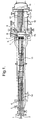
- Figure 1 represents a general layout of an apparatus according to the second embodiment of the present invention.
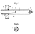
- Figure 2 represents an enlarged view of a mixing zone as used in the present invention.
- Figure 3 represents a cross-section through a mixing means as used in the present invention.
-
- In Figure 1, an oxygen rich oxidant stream is introduced into the apparatus via a first inlet (1). Within the apparatus, the oxidant stream is divided amongst a number of first conduits each having an inlet end (2) and a discharge end (5). A premixed oxidant-free feed stream containing methane and ammonia is introduced into the apparatus via a second inlet (3). However, if desired, it is possible to separately introduce the methane and ammonia through two or more such second inlets. Within the apparatus, the feed stream is divided amongst a number of second conduits each having an inlet end (4) and a discharge end approximately coterminous with that of the first conduits. As shown, each first conduit is associated with and located within a second conduit such that the divided feed stream flows in the annuli formed between the first and second conduits. At the outlet end of each first conduit, the oxidant stream emerges into the feed stream and is mixed in a mixing means (6) to form a mixed stream at such a velocity that detonation of the mixed stream is avoided. After mixing, the mixed stream then proceeds via a discharge orifice (7) to a deflagration arrestor (8) which inhibits the propagation of deflagration of the mixed stream.
- The mixed stream is then received into a reaction zone (15) and from there is directed to a supported catalyst bed (9) capable of promoting the formation of hydrogen cyanide. The effluent stream exit the catalyst bed (9) is then cooled by passing it through an indirect heat exchanger (10), which as shown is a steam raising boiler, to form a partially cooled effluent stream at the heat exchanger exit (11). The partially cooled effluent stream is then routed via at least one effluent conduit (12) so as to flow against the external surface of each second conduit held within a heat exchange section (13) of the apparatus and in a direction which is counter current to the flow of the oxidant and feed streams thereby preheating at least the feed stream and cooling the partially cooled effluent stream to exit from the apparatus via outlet (14). On exit from the apparatus the hydrogen cyanide present in the effluent stream can be recovered using conventional separation techniques.
- In Figure 2, a first conduit (6) is associated with and located within a second conduit (7) as described in Figure 1. The first conduit (6) and second conduit (7) pass from a heat exchange section (9) through a tube sheet (8) into a reaction zone (10). The discharge end of the first conduit has a tapered section (1) which serves to increase the flow area available to the feed stream and a series of radially connecting holes (2) through which the oxidant stream flows to be mixed with the feed stream. The oxidant and feed streams are then mixed in a mixing means (3). Within the mixing means high shear forces are encouraged to promote rapid mixing and the velocity of the mixed stream is maintained as high as possible. On exit from the mixing means (3), the mixed stream flows through a discharge orifice (4) which provides flow connection to a deflagration arrestor (5). After mixing the mixed stream is a detonable mixture of methane, ammonia and oxygen. Consequently, the volume available for flow downstream of the mixing means should be minimised. The deflagration arrestor (5) inhibits propagation of a potential detonation from the reaction zone (10) through to the mixing means (3). After passing through the deflagration arrestor (5) the mixed stream emerges into the reaction zone (10). Preferably, the deflagration arrestor is of a conical construction having slits through which the mixed gas flows thereby providing the mixed stream with a uniform velocity on approach to the catalyst bed.
- In Figure 3, the cross section shows the mixing channels (1) along which the oxidant and feed streams flow during mixing and which provide the necessary high shear forces and velocities.
- The invention is further illustrated by reference to the following example.
- When used to produce hydrogen cyanide from the following oxidant and feed streams
Oxidant Stream kg/hr kmol/hr Oxygen 1211 37.9 Nitrogen 0 0 Feed Stream (premixed) kg/hr kmol/hr Ammonia 848 49.9 Natural Gas (methane) 777 45.7 kg/hr kmol/hr HCN 948.2 35.1 Hydrogen 165.7 82.9 Water 1040.0 57.8 Ammonia 127.9 7.6 Carbon dioxide 68.0 2.4 Carbon monoxide 379.0 8.6 Nitrogen 107.1 3.8
Claims (9)
- A catalytic process for the manufacture of hydrogen cyanide, which process comprises(a) forming(i) an oxygen rich oxidant stream which contains from 30 to 100 % by volume of oxygen,(ii) at least one oxidant-free feed stream supplying methane and ammonia;(b) separately preheating by indirect heat exchange at least one of said oxidant and feed streams to a respective oxidant and feed preheat temperature;(c) rapidly mixing sufficient of the oxidant and feed streams at their respective preheat temperatures in a mixing zone to form a detonable mixed stream at a mixed temperature and which mixed temperature is at least 50°C below the autoignition temperature of the mixed stream;(d) conveying the mixed stream through the mixing zone at a mixing velocity such that detonation of the mixed stream is avoided; and thereafter(e) feeding the mixed stream to a catalyst capable of catalysing the formation of hydrogen cyanide from the mixed stream at the mixed temperature to form an effluent stream containing hydrogen cyanide.
- A process as claimed in claim 1 wherein the oxidant free feed stream is a premixed stream containing a mixture of methane and ammonia.
- A process as claimed in either claim 1 or claim 2 wherein the volume ratio of methane to ammonia is from 1:1 to 1:1.5.
- A process as claimed in any one of claims 1 to 3 wherein the oxidant stream is preheated to a temperature in the range from 200 to 300°C and the at least one feed stream is preheated to a temperature in the range from 300 to 450°C.
- A process as claimed in any one of claims 1 to 4 wherein the mixed temperature is in the range from 200 to 400°C
- A process as claimed in any one of claims 1 to 5 wherein the effluent stream on exiting the catalyst is used in indirect heat exchange to provide a partially cooled effluent stream which is then used to preheat at least one of the oxidant and feed streams.
- A process as claimed in any one of claims 1 to 6 wherein the effluent stream contains from 15 to 20% by volume of HCN and from 30 to 40 % by volume of hydrogen.
- An apparatus for use in the process as defined in any one of claims 1 to 7, which apparatus comprises(a) a first inlet for an oxygen rich oxidant stream;(b) at least one second inlet for at least one oxidant-free feed stream supplying methane and ammonia;(c) a first conduit connected to said first inlet and along which the oxidant stream is able to flow from said first inlet to a discharge end of the first conduit;(d) at least one second conduit connected to said at least one second inlet and along which the at least one feed stream is able to flow from the at least one second inlet to a discharge end of said at least one second conduit and which discharge end is approximately coterminous with the discharge end of said first conduit;(e) a mixing zone located at the discharge end of the first conduit for receiving the oxidant and feed streams;(f) a mixing means located in the mixing zone for effecting rapid mixing of the oxidant and feed streams to form a detonable mixed stream and for conveying the mixed stream through the mixing zone at a mixing velocity such that detonation of the mixed stream is avoided;(g) a discharge orifice providing a flow connecting means between the mixing zone and a deflagration arrestor and through which the mixed stream is able to flow, the deflagration arrestor capable of inhibiting the propagation of a deflagration of the mixed stream back through the discharge orifice into the mixing zone; and(h) a reaction zone for receiving the mixed stream from the deflagration arrestor and for directing the mixed stream to a supported catalyst located in the reaction zone for promoting the formation of hydrogen cyanide from the detonable mixed stream;(i) indirect heat exchange means for preheating at least one of said oxidant and feed streams prior to mixing.
- An apparatus as claimed in claim 8 wherein each first conduit is associated with and located within a second conduit.
Priority Applications (1)
| Application Number | Priority Date | Filing Date | Title |
|---|---|---|---|
| EP96929384A EP0847372B1 (en) | 1995-09-01 | 1996-08-29 | Hydrogen cyanide process and apparatus therefor |
Applications Claiming Priority (4)
| Application Number | Priority Date | Filing Date | Title |
|---|---|---|---|
| EP95113796 | 1995-09-01 | ||
| EP95113796 | 1995-09-01 | ||
| EP96929384A EP0847372B1 (en) | 1995-09-01 | 1996-08-29 | Hydrogen cyanide process and apparatus therefor |
| PCT/GB1996/002103 WO1997009273A1 (en) | 1995-09-01 | 1996-08-29 | Hydrogen cyanide process and apparatus therefor |
Publications (2)
| Publication Number | Publication Date |
|---|---|
| EP0847372A1 EP0847372A1 (en) | 1998-06-17 |
| EP0847372B1 true EP0847372B1 (en) | 2001-06-27 |
Family
ID=8219571
Family Applications (1)
| Application Number | Title | Priority Date | Filing Date |
|---|---|---|---|
| EP96929384A Expired - Lifetime EP0847372B1 (en) | 1995-09-01 | 1996-08-29 | Hydrogen cyanide process and apparatus therefor |
Country Status (13)
| Country | Link |
|---|---|
| US (2) | US6491876B2 (en) |
| EP (1) | EP0847372B1 (en) |
| JP (1) | JP3889442B2 (en) |
| KR (1) | KR100411692B1 (en) |
| CN (1) | CN1095806C (en) |
| AT (1) | ATE202541T1 (en) |
| AU (1) | AU702825C (en) |
| BR (1) | BR9610149A (en) |
| CA (1) | CA2230017C (en) |
| DE (1) | DE69613581T2 (en) |
| ES (1) | ES2158339T3 (en) |
| TW (1) | TW389741B (en) |
| WO (1) | WO1997009273A1 (en) |
Cited By (1)
| Publication number | Priority date | Publication date | Assignee | Title |
|---|---|---|---|---|
| EP1604947A1 (en) * | 2004-06-07 | 2005-12-14 | ETH Zürich | Process and apparatus for producing hydrogen or ammonia |
Families Citing this family (26)
| Publication number | Priority date | Publication date | Assignee | Title |
|---|---|---|---|---|
| DE69613581T2 (en) * | 1995-09-01 | 2002-04-25 | Ineos Acrylics Uk Ltd., Southampton | METHOD AND DEVICE FOR PRODUCING CYAN HYDROGEN |
| DE19754988A1 (en) * | 1997-12-11 | 1999-06-17 | Degussa | Production of hydrocyanic acid by the Andrussow process |
| DE19810484A1 (en) * | 1998-03-11 | 1999-09-16 | Degussa | Process for the production of hydrocyanic acid |
| US6221327B1 (en) | 1998-05-15 | 2001-04-24 | Rohm And Haas Company | Catalyst system using flow-through radiation shielding and a process for producing hydrogen cyanide using the same |
| AU4090600A (en) * | 1999-06-30 | 2001-01-04 | Rohm And Haas Company | High performance heat exchangers |
| US6649137B2 (en) | 2000-05-23 | 2003-11-18 | Rohm And Haas Company | Apparatus with improved safety features for high temperature industrial processes |
| DE10034194A1 (en) | 2000-07-13 | 2003-09-11 | Roehm Gmbh | Process for the preparation of hydrogen cyanide |
| DE10034193A1 (en) | 2000-07-13 | 2002-03-28 | Roehm Gmbh | Process for the production of hydrogen cyanide |
| DE102007014586A1 (en) | 2007-03-23 | 2008-09-25 | Evonik Röhm Gmbh | Process for the production of hydrogen cyanide (HCN) |
| DE102007034715A1 (en) * | 2007-07-23 | 2009-01-29 | Evonik Röhm Gmbh | Reactor for the production of hydrogen cyanide by the Andrussow method |
| TWI390145B (en) * | 2008-03-31 | 2013-03-21 | Rohm & Haas | Method and apparatus for deflagration pressure attenuation |
| WO2014099607A1 (en) | 2012-12-18 | 2014-06-26 | Invista Technologies S.A. R. L. | Integrated process for hexamethylenediamine production |
| AU2013363333A1 (en) * | 2012-12-18 | 2015-07-30 | Invista Technologies S.A.R.L. | Process for producing hydrogen cyanide and recovering hydrogen |
| CN103864113B (en) | 2012-12-18 | 2018-01-19 | 英威达纺织(英国)有限公司 | Use the method for converter production hydrogen cyanide |
| WO2014099601A1 (en) * | 2012-12-18 | 2014-06-26 | Invista Technologies S.A.R.L. | Process for stabilizing heat exchanger tubes in andrussow process |
| CN103864623B (en) * | 2012-12-18 | 2017-04-12 | 英威达科技公司 | Integrated process for diamine production |
| WO2014099605A1 (en) * | 2012-12-18 | 2014-06-26 | Invista Technologies S.A R.L. | Process for producing hydrogen cyanide using flow straightener |
| CN103864109A (en) * | 2012-12-18 | 2014-06-18 | 因温斯特技术公司 | Systems and methods for recycling in the Andrussow process |
| EP2935094A1 (en) * | 2012-12-18 | 2015-10-28 | Invista Technologies S.à.r.l. | Apparatus and method for hydrogen recovery in an andrussow process |
| EP2935115A1 (en) | 2012-12-18 | 2015-10-28 | Invista Technologies S.à.r.l. | Operational controls for inert gas blanketing for andrussow process |
| CN113816398B (en) * | 2012-12-18 | 2023-11-10 | 英威达纺织(英国)有限公司 | Ammonia ratio variation in Anderlufu process |
| CN110127724A (en) * | 2013-07-12 | 2019-08-16 | 英威达纺织(英国)有限公司 | Hydrogen cyanide production method using second waste heat boiler |
| FR3008626B1 (en) * | 2013-07-19 | 2015-08-07 | Arkema France | REACTOR FOR PREPARING HYDROGEN CYANIDE BY THE ANDRUSSOW PROCESS, EQUIPMENT COMPRISING SAID REACTOR AND METHOD USING SUCH EQUIPMENT |
| FR3008692B1 (en) | 2013-07-19 | 2016-12-23 | Arkema France | INSTALLATION AND PROCESS FOR THE PREPARATION OF HYDROGEN CYANIDE |
| US10323888B2 (en) * | 2016-04-18 | 2019-06-18 | Corrosion Monitoring Service Inc. | System and method for installing external corrosion guards |
| CN120268332A (en) * | 2024-01-05 | 2025-07-08 | 中国天辰工程有限公司 | Reactor for preparing hydrogen cyanide |
Family Cites Families (16)
| Publication number | Priority date | Publication date | Assignee | Title |
|---|---|---|---|---|
| US1934838A (en) | 1930-04-14 | 1933-11-14 | Ig Farbenindustrie Ag | Production of hydrocyanic acid |
| DE1005049B (en) * | 1951-12-06 | 1957-03-28 | Goodrich Co B F | Process for the production of hydrogen cyanide |
| US2803522A (en) * | 1953-04-15 | 1957-08-20 | Du Pont | Manufacture of hydrogen cyanide |
| US3112177A (en) * | 1959-11-11 | 1963-11-26 | Toyo Koatsu Ind Inc | Method of separating ammonia from hydrogen cyanide |
| US3104945A (en) * | 1961-07-19 | 1963-09-24 | Du Pont | Method of producing hydrogen cyanide |
| DE1161870B (en) | 1961-09-19 | 1964-01-30 | Hans J Zimmer Verfahrenstechni | Process for the production of hydrogen cyanide |
| US3215495A (en) * | 1962-01-23 | 1965-11-02 | Du Pont | Apparatus and process for preparing hydrogen cyanide |
| DE1190445B (en) * | 1962-09-29 | 1965-04-08 | Hans J Zimmer Verfahrenstechni | Process for the production of hydrogen cyanide and nitriles |
| NL6604519A (en) | 1965-04-14 | 1966-10-17 | ||
| US3376500A (en) | 1966-04-25 | 1968-04-02 | Varian Associates | Direct reading magnetic field intensity indicating apparatus |
| US4107278A (en) | 1976-08-16 | 1978-08-15 | E. I. Du Pont De Nemours And Company | Process for making HCN |
| US4128622A (en) * | 1976-08-27 | 1978-12-05 | E. I. Du Pont De Nemours And Company | Process for producing hydrogen cyanide |
| PL109343B1 (en) | 1978-06-19 | 1981-11-30 | Politechnika Wroclawska | Method of producing hydrogen cyanide |
| US5266291A (en) * | 1992-05-05 | 1993-11-30 | Praxair Technology, Inc. | Packed bed arrangement for oxidation reaction system |
| US5360603A (en) * | 1993-08-23 | 1994-11-01 | Praxair Technology, Inc. | Packed bed arrangement useful for mixing and/or oxidation |
| DE69613581T2 (en) * | 1995-09-01 | 2002-04-25 | Ineos Acrylics Uk Ltd., Southampton | METHOD AND DEVICE FOR PRODUCING CYAN HYDROGEN |
-
1996
- 1996-08-29 DE DE69613581T patent/DE69613581T2/en not_active Expired - Lifetime
- 1996-08-29 BR BR9610149A patent/BR9610149A/en not_active IP Right Cessation
- 1996-08-29 AT AT96929384T patent/ATE202541T1/en not_active IP Right Cessation
- 1996-08-29 KR KR10-1998-0701566A patent/KR100411692B1/en not_active Expired - Fee Related
- 1996-08-29 JP JP51093197A patent/JP3889442B2/en not_active Expired - Fee Related
- 1996-08-29 CN CN96197711A patent/CN1095806C/en not_active Expired - Fee Related
- 1996-08-29 EP EP96929384A patent/EP0847372B1/en not_active Expired - Lifetime
- 1996-08-29 ES ES96929384T patent/ES2158339T3/en not_active Expired - Lifetime
- 1996-08-29 WO PCT/GB1996/002103 patent/WO1997009273A1/en not_active Ceased
- 1996-08-29 US US09/029,536 patent/US6491876B2/en not_active Expired - Fee Related
- 1996-08-29 AU AU68799/96A patent/AU702825C/en not_active Ceased
- 1996-08-29 CA CA002230017A patent/CA2230017C/en not_active Expired - Fee Related
- 1996-09-05 TW TW085110881A patent/TW389741B/en active
-
2002
- 2002-05-28 US US10/154,922 patent/US6656442B2/en not_active Expired - Fee Related
Cited By (2)
| Publication number | Priority date | Publication date | Assignee | Title |
|---|---|---|---|---|
| WO2005118465A1 (en) * | 2004-06-04 | 2005-12-15 | ETH Zürich | Process and apparatus for producing concurrently hydrogen or ammonia and metal oxide nanoparticles |
| EP1604947A1 (en) * | 2004-06-07 | 2005-12-14 | ETH Zürich | Process and apparatus for producing hydrogen or ammonia |
Also Published As
| Publication number | Publication date |
|---|---|
| US6491876B2 (en) | 2002-12-10 |
| DE69613581D1 (en) | 2001-08-02 |
| JP3889442B2 (en) | 2007-03-07 |
| AU6879996A (en) | 1997-03-27 |
| DE69613581T2 (en) | 2002-04-25 |
| CN1095806C (en) | 2002-12-11 |
| CN1200102A (en) | 1998-11-25 |
| CA2230017C (en) | 2006-06-20 |
| KR19990044326A (en) | 1999-06-25 |
| US6656442B2 (en) | 2003-12-02 |
| TW389741B (en) | 2000-05-11 |
| ES2158339T3 (en) | 2001-09-01 |
| CA2230017A1 (en) | 1997-03-13 |
| JPH11512070A (en) | 1999-10-19 |
| KR100411692B1 (en) | 2004-02-18 |
| MX9801546A (en) | 1998-05-31 |
| WO1997009273A1 (en) | 1997-03-13 |
| EP0847372A1 (en) | 1998-06-17 |
| BR9610149A (en) | 1999-02-02 |
| US20020039553A1 (en) | 2002-04-04 |
| ATE202541T1 (en) | 2001-07-15 |
| AU702825B2 (en) | 1999-03-04 |
| US20020182137A1 (en) | 2002-12-05 |
| AU702825C (en) | 2002-09-19 |
Similar Documents
| Publication | Publication Date | Title |
|---|---|---|
| AU702825C (en) | Hydrogen cyanide process and apparatus therefor | |
| EP1017619B1 (en) | Oxygen-fuel boost reformer process and apparatus | |
| US7255840B2 (en) | Autothermal reactor and method for production of synthesis gas | |
| US6267912B1 (en) | Distributed injection catalytic partial oxidation process and apparatus for producing synthesis gas | |
| US5937632A (en) | Method for operating a gas turbine group with catalytic gas generator | |
| US3958951A (en) | Convective power reformer equipment and system | |
| CA2286286A1 (en) | Rapid injection process and apparatus for producing synthesis gas | |
| CA2286273A1 (en) | Distributed injection process and apparatus for producing synthesis gas | |
| CA2285973A1 (en) | Multi-injector autothermal reforming process and apparatus for producing synthesis gas | |
| US11542158B2 (en) | Burner and process for producing synthesis gas | |
| US20250043952A1 (en) | Flow restrictors for use on burners | |
| EP3917874B1 (en) | A process for partial oxidation | |
| US4230278A (en) | Apparatus for reducing hydrocarbon fuel requirement for Haber ammonia synthesis | |
| US6455012B1 (en) | Acid gas burner and reactor apparatus and method | |
| MXPA98001546A (en) | Procedure for hydrogen cyanide and apparatus | |
| KR20250129706A (en) | Process for producing a synthesis gas product containing hydrogen | |
| TH28563A (en) | For the action of processes with catalysts Or without catalysts Where oxygen is one of the reactants |
Legal Events
| Date | Code | Title | Description |
|---|---|---|---|
| PUAI | Public reference made under article 153(3) epc to a published international application that has entered the european phase |
Free format text: ORIGINAL CODE: 0009012 |
|
| 17P | Request for examination filed |
Effective date: 19980212 |
|
| AK | Designated contracting states |
Kind code of ref document: A1 Designated state(s): AT BE CH DE DK ES FI FR GB GR IE IT LI LU MC NL PT SE |
|
| 17Q | First examination report despatched |
Effective date: 19980525 |
|
| TPAD | Observations filed by third parties |
Free format text: ORIGINAL CODE: EPIDOS TIPA |
|
| GRAG | Despatch of communication of intention to grant |
Free format text: ORIGINAL CODE: EPIDOS AGRA |
|
| GRAG | Despatch of communication of intention to grant |
Free format text: ORIGINAL CODE: EPIDOS AGRA |
|
| GRAH | Despatch of communication of intention to grant a patent |
Free format text: ORIGINAL CODE: EPIDOS IGRA |
|
| RAP1 | Party data changed (applicant data changed or rights of an application transferred) |
Owner name: INEOS ACRYLICS UK LIMITED |
|
| GRAH | Despatch of communication of intention to grant a patent |
Free format text: ORIGINAL CODE: EPIDOS IGRA |
|
| GRAA | (expected) grant |
Free format text: ORIGINAL CODE: 0009210 |
|
| AK | Designated contracting states |
Kind code of ref document: B1 Designated state(s): AT BE CH DE DK ES FI FR GB GR IE IT LI LU MC NL PT SE |
|
| PG25 | Lapsed in a contracting state [announced via postgrant information from national office to epo] |
Ref country code: LI Free format text: LAPSE BECAUSE OF FAILURE TO SUBMIT A TRANSLATION OF THE DESCRIPTION OR TO PAY THE FEE WITHIN THE PRESCRIBED TIME-LIMIT Effective date: 20010627 Ref country code: FI Free format text: LAPSE BECAUSE OF FAILURE TO SUBMIT A TRANSLATION OF THE DESCRIPTION OR TO PAY THE FEE WITHIN THE PRESCRIBED TIME-LIMIT Effective date: 20010627 Ref country code: CH Free format text: LAPSE BECAUSE OF FAILURE TO SUBMIT A TRANSLATION OF THE DESCRIPTION OR TO PAY THE FEE WITHIN THE PRESCRIBED TIME-LIMIT Effective date: 20010627 Ref country code: AT Free format text: LAPSE BECAUSE OF FAILURE TO SUBMIT A TRANSLATION OF THE DESCRIPTION OR TO PAY THE FEE WITHIN THE PRESCRIBED TIME-LIMIT Effective date: 20010627 |
|
| REF | Corresponds to: |
Ref document number: 202541 Country of ref document: AT Date of ref document: 20010715 Kind code of ref document: T |
|
| REG | Reference to a national code |
Ref country code: CH Ref legal event code: EP |
|
| REG | Reference to a national code |
Ref country code: IE Ref legal event code: FG4D |
|
| REF | Corresponds to: |
Ref document number: 69613581 Country of ref document: DE Date of ref document: 20010802 |
|
| PG25 | Lapsed in a contracting state [announced via postgrant information from national office to epo] |
Ref country code: LU Free format text: LAPSE BECAUSE OF NON-PAYMENT OF DUE FEES Effective date: 20010829 Ref country code: IE Free format text: LAPSE BECAUSE OF NON-PAYMENT OF DUE FEES Effective date: 20010829 |
|
| REG | Reference to a national code |
Ref country code: ES Ref legal event code: FG2A Ref document number: 2158339 Country of ref document: ES Kind code of ref document: T3 |
|
| ET | Fr: translation filed | ||
| PG25 | Lapsed in a contracting state [announced via postgrant information from national office to epo] |
Ref country code: SE Free format text: LAPSE BECAUSE OF FAILURE TO SUBMIT A TRANSLATION OF THE DESCRIPTION OR TO PAY THE FEE WITHIN THE PRESCRIBED TIME-LIMIT Effective date: 20010927 Ref country code: PT Free format text: LAPSE BECAUSE OF FAILURE TO SUBMIT A TRANSLATION OF THE DESCRIPTION OR TO PAY THE FEE WITHIN THE PRESCRIBED TIME-LIMIT Effective date: 20010927 Ref country code: DK Free format text: LAPSE BECAUSE OF FAILURE TO SUBMIT A TRANSLATION OF THE DESCRIPTION OR TO PAY THE FEE WITHIN THE PRESCRIBED TIME-LIMIT Effective date: 20010927 |
|
| PG25 | Lapsed in a contracting state [announced via postgrant information from national office to epo] |
Ref country code: GR Free format text: LAPSE BECAUSE OF FAILURE TO SUBMIT A TRANSLATION OF THE DESCRIPTION OR TO PAY THE FEE WITHIN THE PRESCRIBED TIME-LIMIT Effective date: 20010928 |
|
| REG | Reference to a national code |
Ref country code: CH Ref legal event code: PL |
|
| REG | Reference to a national code |
Ref country code: GB Ref legal event code: IF02 |
|
| PG25 | Lapsed in a contracting state [announced via postgrant information from national office to epo] |
Ref country code: MC Free format text: LAPSE BECAUSE OF NON-PAYMENT OF DUE FEES Effective date: 20020301 |
|
| PLBE | No opposition filed within time limit |
Free format text: ORIGINAL CODE: 0009261 |
|
| STAA | Information on the status of an ep patent application or granted ep patent |
Free format text: STATUS: NO OPPOSITION FILED WITHIN TIME LIMIT |
|
| REG | Reference to a national code |
Ref country code: IE Ref legal event code: MM4A |
|
| 26N | No opposition filed | ||
| NLT1 | Nl: modifications of names registered in virtue of documents presented to the patent office pursuant to art. 16 a, paragraph 1 |
Owner name: LUCITE INTERNATIONAL UK LIMITED |
|
| REG | Reference to a national code |
Ref country code: FR Ref legal event code: CD |
|
| PGFP | Annual fee paid to national office [announced via postgrant information from national office to epo] |
Ref country code: DE Payment date: 20110823 Year of fee payment: 16 Ref country code: FR Payment date: 20110901 Year of fee payment: 16 Ref country code: ES Payment date: 20110812 Year of fee payment: 16 Ref country code: GB Payment date: 20110819 Year of fee payment: 16 |
|
| PGFP | Annual fee paid to national office [announced via postgrant information from national office to epo] |
Ref country code: IT Payment date: 20110824 Year of fee payment: 16 Ref country code: BE Payment date: 20110811 Year of fee payment: 16 Ref country code: NL Payment date: 20110825 Year of fee payment: 16 |
|
| BERE | Be: lapsed |
Owner name: *LUCITE INTERNATIONAL UK LTD Effective date: 20120831 |
|
| REG | Reference to a national code |
Ref country code: NL Ref legal event code: V1 Effective date: 20130301 |
|
| GBPC | Gb: european patent ceased through non-payment of renewal fee |
Effective date: 20120829 |
|
| PG25 | Lapsed in a contracting state [announced via postgrant information from national office to epo] |
Ref country code: NL Free format text: LAPSE BECAUSE OF NON-PAYMENT OF DUE FEES Effective date: 20130301 |
|
| REG | Reference to a national code |
Ref country code: FR Ref legal event code: ST Effective date: 20130430 |
|
| PG25 | Lapsed in a contracting state [announced via postgrant information from national office to epo] |
Ref country code: BE Free format text: LAPSE BECAUSE OF NON-PAYMENT OF DUE FEES Effective date: 20120831 Ref country code: IT Free format text: LAPSE BECAUSE OF NON-PAYMENT OF DUE FEES Effective date: 20120829 |
|
| PG25 | Lapsed in a contracting state [announced via postgrant information from national office to epo] |
Ref country code: GB Free format text: LAPSE BECAUSE OF NON-PAYMENT OF DUE FEES Effective date: 20120829 Ref country code: DE Free format text: LAPSE BECAUSE OF NON-PAYMENT OF DUE FEES Effective date: 20130301 |
|
| PG25 | Lapsed in a contracting state [announced via postgrant information from national office to epo] |
Ref country code: FR Free format text: LAPSE BECAUSE OF NON-PAYMENT OF DUE FEES Effective date: 20120831 |
|
| REG | Reference to a national code |
Ref country code: DE Ref legal event code: R119 Ref document number: 69613581 Country of ref document: DE Effective date: 20130301 |
|
| REG | Reference to a national code |
Ref country code: ES Ref legal event code: FD2A Effective date: 20131021 |
|
| PG25 | Lapsed in a contracting state [announced via postgrant information from national office to epo] |
Ref country code: ES Free format text: LAPSE BECAUSE OF NON-PAYMENT OF DUE FEES Effective date: 20120830 |