EP0846905B1 - A method for fastening a part or component to a body of an automobile and an adapter portion for performing the method - Google Patents
A method for fastening a part or component to a body of an automobile and an adapter portion for performing the method Download PDFInfo
- Publication number
- EP0846905B1 EP0846905B1 EP97118396A EP97118396A EP0846905B1 EP 0846905 B1 EP0846905 B1 EP 0846905B1 EP 97118396 A EP97118396 A EP 97118396A EP 97118396 A EP97118396 A EP 97118396A EP 0846905 B1 EP0846905 B1 EP 0846905B1
- Authority
- EP
- European Patent Office
- Prior art keywords
- adapter
- support sheet
- flange portion
- foot
- foot portion
- Prior art date
- Legal status (The legal status is an assumption and is not a legal conclusion. Google has not performed a legal analysis and makes no representation as to the accuracy of the status listed.)
- Expired - Lifetime
Links
- 238000000034 method Methods 0.000 title claims description 16
- 238000007789 sealing Methods 0.000 claims description 11
- 239000000463 material Substances 0.000 claims description 9
- 239000004831 Hot glue Substances 0.000 claims description 5
- 210000002105 tongue Anatomy 0.000 claims description 3
- 239000000853 adhesive Substances 0.000 claims description 2
- 230000001070 adhesive effect Effects 0.000 claims description 2
- 230000002093 peripheral effect Effects 0.000 claims 3
- 230000000694 effects Effects 0.000 claims 1
- 239000004033 plastic Substances 0.000 description 10
- 229920003023 plastic Polymers 0.000 description 10
- 239000002184 metal Substances 0.000 description 8
- 238000004519 manufacturing process Methods 0.000 description 4
- 238000005260 corrosion Methods 0.000 description 2
- 230000007797 corrosion Effects 0.000 description 2
- 230000000717 retained effect Effects 0.000 description 2
- 239000002966 varnish Substances 0.000 description 2
- XLYOFNOQVPJJNP-UHFFFAOYSA-N water Substances O XLYOFNOQVPJJNP-UHFFFAOYSA-N 0.000 description 2
- 229920005830 Polyurethane Foam Polymers 0.000 description 1
- 239000000356 contaminant Substances 0.000 description 1
- 230000001627 detrimental effect Effects 0.000 description 1
- 239000013536 elastomeric material Substances 0.000 description 1
- 238000005265 energy consumption Methods 0.000 description 1
- 239000012530 fluid Substances 0.000 description 1
- 239000000446 fuel Substances 0.000 description 1
- 239000012943 hotmelt Substances 0.000 description 1
- 239000011496 polyurethane foam Substances 0.000 description 1
- 229920002725 thermoplastic elastomer Polymers 0.000 description 1
- 238000009966 trimming Methods 0.000 description 1
Images

Classifications
-
- F—MECHANICAL ENGINEERING; LIGHTING; HEATING; WEAPONS; BLASTING
- F16—ENGINEERING ELEMENTS AND UNITS; GENERAL MEASURES FOR PRODUCING AND MAINTAINING EFFECTIVE FUNCTIONING OF MACHINES OR INSTALLATIONS; THERMAL INSULATION IN GENERAL
- F16L—PIPES; JOINTS OR FITTINGS FOR PIPES; SUPPORTS FOR PIPES, CABLES OR PROTECTIVE TUBING; MEANS FOR THERMAL INSULATION IN GENERAL
- F16L3/00—Supports for pipes, cables or protective tubing, e.g. hangers, holders, clamps, cleats, clips, brackets
-
- F—MECHANICAL ENGINEERING; LIGHTING; HEATING; WEAPONS; BLASTING
- F16—ENGINEERING ELEMENTS AND UNITS; GENERAL MEASURES FOR PRODUCING AND MAINTAINING EFFECTIVE FUNCTIONING OF MACHINES OR INSTALLATIONS; THERMAL INSULATION IN GENERAL
- F16B—DEVICES FOR FASTENING OR SECURING CONSTRUCTIONAL ELEMENTS OR MACHINE PARTS TOGETHER, e.g. NAILS, BOLTS, CIRCLIPS, CLAMPS, CLIPS OR WEDGES; JOINTS OR JOINTING
- F16B5/00—Joining sheets or plates, e.g. panels, to one another or to strips or bars parallel to them
- F16B5/06—Joining sheets or plates, e.g. panels, to one another or to strips or bars parallel to them by means of clamps or clips
- F16B5/0607—Joining sheets or plates, e.g. panels, to one another or to strips or bars parallel to them by means of clamps or clips joining sheets or plates to each other
- F16B5/0621—Joining sheets or plates, e.g. panels, to one another or to strips or bars parallel to them by means of clamps or clips joining sheets or plates to each other in parallel relationship
- F16B5/0657—Joining sheets or plates, e.g. panels, to one another or to strips or bars parallel to them by means of clamps or clips joining sheets or plates to each other in parallel relationship at least one of the plates providing a raised structure, e.g. of the doghouse type, for connection with the clamps or clips of the other plate
-
- F—MECHANICAL ENGINEERING; LIGHTING; HEATING; WEAPONS; BLASTING
- F16—ENGINEERING ELEMENTS AND UNITS; GENERAL MEASURES FOR PRODUCING AND MAINTAINING EFFECTIVE FUNCTIONING OF MACHINES OR INSTALLATIONS; THERMAL INSULATION IN GENERAL
- F16B—DEVICES FOR FASTENING OR SECURING CONSTRUCTIONAL ELEMENTS OR MACHINE PARTS TOGETHER, e.g. NAILS, BOLTS, CIRCLIPS, CLAMPS, CLIPS OR WEDGES; JOINTS OR JOINTING
- F16B11/00—Connecting constructional elements or machine parts by sticking or pressing them together, e.g. cold pressure welding
- F16B11/006—Connecting constructional elements or machine parts by sticking or pressing them together, e.g. cold pressure welding by gluing
Definitions
- the present invention relates to a method for mounting parts such as a cable, tube, conduit, hose or the like on a support sheet, e.g. to a body of an automobile as defined in the preamble of patent claim 1.
- the present invention relates also to an adapter for such mounting according to patent claim 3.
- Plastic fasteners are widely used in the automotive industry. They are used for example for the attachment of coverings, insulating mats, trimming and covering strips, but also to attach cables and cable bundles, hose packages for brake fluid and fuel conduits as well as for other tubings.
- the most common type of attachment of such plastics fasteners is presently an attachment thereof to upstanding bolts (weld bolts) which are welded to the body at the respective locations.
- This method has replaced another method which used an attachment in holes of sheet metal portions, for example by means of expansion rivets, expansion nuts or similar fastening means. It is known that holes have the drawback of permitting water vapour, water and contaminants to pass through so as to cause corrosion.
- a one-piece plastic drive fastener having a head and a shank, the shank including a generally cruciform cross section presenting a plurality of generally flat, axially extending surfaces and a plurality of angular axially extending recesses between adjacent flat surfaces. With this shank the fastener can be fixedly retained in a hole of a support sheet.
- the head of the fastener includes a radially extending flange which is adapted to engage the associated surface of the sheet support.
- the weld bolts do not suffer from the above mentioned drawbacks and may be attached in a relatively simple manner. Also the mounting of plastics fasteners to upstanding bolts causes only very little assembly expenditure. However, upstanding bolts can be broken off or be damaged. The required repair expenditure during manufacture of the automobiles or eventually in the repair workshop is extremely high.
- German patent application 34 45 935 discloses a cable fastening element including a shoe-shaped head portion which is connected to a shoe-receiving head portion of a fastener element which is adapted to be attached to the body of the automobile.
- the cable holder may be fixed to the cable or cable bundle by pre-assembly.
- the method of the present invention returns to the prior method for attaching plastic fasteners in mounting apertures at the support sheet metal portion to which a part is to be mounted.
- the apertures are formed for example in the sheet metal blank for the blank body.
- an adapter is inserted into the mounting aperture of the blank body.
- the adapter portion is made of a plastic material which is substantially deformation-resistant at 180°C or higher. "Deformation-resistant" means that an adapter while not being stressed in any way retains its shape at the above mentioned temperature. A certain plasticity of the higher temperature is not detrimental because after the temperature has sunk below the critical temperature the material will have been sufficiently hardened so as to resist also mechanical stresses as they may occur when a holding portion or the part to be fastened is being assembled.
- the adapter portion is mounted into the mounting aperture in a substantially gas-tight manner. This is achieved by mounting and sealing the adapter portion by a sealing ring.
- the adapter is mechanically secured against withdrawal from the mounting aperture by means of an undercut. This is obtained by having the adapter engaged behind the rim of the mounting aperture when it is being inserted thereinto. This ensures the necessary axial fixing of the adapter.
- the adapter includes an adapter head which is adapted to be connected to a head of a holding portion; the adapter head and the head of the holding portion may be connected to each other via a releasable or not releasable snap joint.
- Such snap joint will be obtained only at a later date when the support sheet metal portion was processed, for example coated by a primer or a varnish.
- varnishing is performed at increased temperatures.
- the holding portion does not need to resist these temperatures; therefore it may be made of a less expensive plastics material.
- the method of the invention results in a substantially reduced expenditure in the manufacture of automobile bodies and in a substantial reduction of replacement and repair services. Furthermore, energy consumption is being reduced. Idle times in the manufacturing factories will be reduced thereby. Furthermore, the expenditure for finishing operations will become less. Finally, the method of the invention allows to provide universal fasteners whereby the great number of different fastener elements presently used can be reduced.
- the adapter for performing the method of the invention includes a foot enabling an undercut, and a seal. Furthermore, it includes a radial flange overlapping the mounting aperture, with the adapter head being positioned on the side of the flange opposite to the foot.
- a sealing ring of hot melt adhesive is provided on the lower surface of the flange portion to provide a gas-tight adhesive connection between the lower surface of the flange portion and the upper surface of the support sheet.
- the foot may comprise at least two parallel rows of snapping tongues parallel to the axis.
- the foot and the mounting aperture may form a bayonet joint.
- the foot may comprise an expansion nut.
- the expansion nut which may be snapped into the mounting hole includes an aperture for a mounting bolt or a screw; the holding portion may be attached to the expansion nut by means of the mounting bolt, or the bolt itself may include mounting means for a holding portion.
- the foot may comprise an expansion rivet.
- the foot may have a first portion of polygonal cross section adjacent the flange, which first portion is followed by a second portion also of polygonal cross section.
- the foot while being in a first rotary position is inserted into the mounting hole and will be rotated thereafter such that said first portion engages the wall of the mounting hole.
- said second portion will form an undercut so that the foot cannot be withdrawn anymore from the mounting hole.
- Such mounting methods may be used in particular with non-circular mounting holes.
- an elastomeric sealing ring positioned on the side of the flange facing the foot may be provided.
- the flange may include a continuous or annular rib which when the foot is being assembled engages the opposite side of the support sheet.
- Attaching a holding portion to the adapter head may occur for example in an axial direction or transversely to the axis of the foot.
- Various designs are possible in this connection.
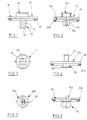
- an adapter portion 10 is integrally formed of plastics material.
- the material is of a type which is deformation-resistant at a temperature of 180° or even more. Such material is known per se.
- the adapter portion 10 includes a foot 12 of the so-called eagle clip type having guide ribs extending parallel to the axis and circumferentially spaced about elongated foot 12, and a row of flexible tongues extending parallel to the axis or diagonally and engaging behind the rim of a hole (not shown).
- the foot 12 is connected to the bottom side of a flange 18 which is e.g. of circular shape and which extends radially beyond the foot 12 for a substantial amount.
- the top side of the flange 18 includes means 20 for receiving a not-shown holding portion.
- the receiving means 10 can be for example of the type which is disclosed in German patent application 34 45 935 and which receives a shoe connected to a retaining element for conduits.
- the bottom side of the flange 18 includes a ring 22 of hot-melt adhesive.
- the foot 16 of the adapter portion 10 will be inserted into a pre-cut hole of for example a sheet metal portion of a blank body of an automobile and is retained therein by itself.
- the hot-melt adhesive 22 will be heated so that it will adhere to the metal sheet resulting in a respective seal within the mounting hole.
- the not-shown holding portion may be mounted to the adapter portion.
- the adapter portion 10a of Fig. 2 is of similar structure as that in Fig. 1 so that similar elements have been designated by the same reference numerals. It differs from the adapter portion in Fig. 1 in that the flange carries a dampening layer 24 of a material suited to absorb noise and vibrations so as to prevent vibrations from being transferred to the not-shown fastening member.
- the adapter portion 10b has a foot formed as a shank 26 to which a disk 28 of increased diameter has been mounted.
- the disk 28 is of elongated shape as may be seen in Fig. 5. This allows to provide a bayonet joint with a non-circular hole.
- a threaded pin 30 is provided on the top side of the flange 18b. Its purpose is to mount a fastening or mounting portion.
- the foot of the adapter portion 10c comprises an expansion nut 32 which opens in an upward direction above the flange 18c so that threading for example a metal bolt thereinto will secure the expansion nut 32 in the not-shown mounting hole.
- the metallic threaded pin may receive a holding portion at the same time.
- the adapter portion 10d in Fig. 7 includes a foot 34 comprised of an expansion rivet for being mounted into a mounting hole.
- the top side of the flange 18d carries a connector portion 36 for a holding portion which again may be mounted in the manner of a bayonet joint.
- the adapter portion 10e in Fig. 8 includes a spherical annular flange 18e which is slightly flexible. At its bottom side it includes an annular rib 40 and a seal 42 of an elastomeric material such as polyurethane foam, a thermoplastic elastomer or the like.
- a foot 44 at the bottom side of the flange 18e includes a first portion 46 of a polygonal cross section which is followed by a second portion 48 also of polygonal cross section, with the cross sections of both portions 46, 48 being offset with respect to each other in a rotary direction.
- the foot 44 serves primarily to mount the adapter portion 10e to an uncircular, for example square hole.
- the first portion 48 which conforms to the contour of the hole is being inserted in the proper orientation, whereafter the adapter portion is rotated for example for 45° so that a clamping joint with the first portion 46 within the hole will be obtained or the edges will be slightly deformed so that the portion 46 fits into the hole.
- the second portion 48 now prevents withdrawal thereof.
- An adapter head 50 includes a shank 52 with circumferentially spaced radial integral ribs 54 to assist the mounting and prevent rotation when a head of a holding portion (not shown) is being assembled thereon.
- the free end of the shank 52 carries a semispherical head 54 which together with the shank 52 forms a lower shoulder 56 to provide an undercut joint with a respective receiving means at the holding portion (not shown).
- the adapter portion of the invention is suited both for assembly in a direction from the outside to the inside and for assembly in a direction from the inside to the outside.
Landscapes
- Engineering & Computer Science (AREA)
- General Engineering & Computer Science (AREA)
- Mechanical Engineering (AREA)
- Connection Of Plates (AREA)
- Lining Or Joining Of Plastics Or The Like (AREA)
- Supports For Pipes And Cables (AREA)
- Insertion Pins And Rivets (AREA)
Description
- Fig. 1
- shows schematically a cross section of a first embodiment of an adapter portion of the invention.
- Fig. 2
- shows a cross section of a second embodiment of an adapter portion.
- Fig. 3
- shows an elevation of the adapter portion in Fig. 1 in a reduced scale.
- Fig. 4
- shows a third embodiment of an adapter portion of the invention.
- Fig. 5
- shows a view of the adapter portion in Fig. 4 from below.
- Fig. 6
- shows a fourth embodiment of an adapter portion of the invention.
- Fig. 7
- shows a fifth embodiment of an adapter portion of the invention.
- Fig. 8
- shows a sixth embodiment of an adapter portion of the invention.
Claims (11)
- A method for mounting parts or components on a support sheet, e.g. of the body of an automobile, wherein the sheet having a first horizontally disposed upper surface and a second horizontally disposed lower surface is provided with a mounting aperture and is varnished, an adapter (10, 10a, 10b, 10d) having a flange portion (18, 18a, 18b, 18c, 18d) with an upper and a lower surface and a peripheral edge defined at a juncture between the upper and the lower surfaces and further having an axially extending foot portion (12, 32, 34) defining a vertical axis which is integrally connected to the lower surface of the flange portion (18, 18a, 18b, 18c, 18d) is mounted to the support sheet in that the foot portion (12, 32, 34) is inserted into the mounting aperture, with means on the foot portion engaging the second horizontally disposed lower surface of the support sheet to fixedly retain the adapter in a mounted state upon the support sheet, wherein further sealing means seal the flange portion (18, 18a, 18b, 18c, 18d) relative to the upper surface of the support sheet, and mounting the part or a component on a vertically upstanding axially extending head portion (20, 20a, 30, 36) coaxially disposed with respect to the foot portion and integrally connected the second upper surface of the flange portion (18, 18a, 18b, 18c, 18d), characterized in that the mounting of the adapter (10, 10a, 10b, 10c, 10d) is carried out before the varnishing of the support sheet takes place, the adapter (10, 10a, 10b, 10c, 10d) is made of a material which is resistive against temperatures of 180°C and higher without loosing its shape, and the further sealing means are a sealing ring (22, 22a, 22b, 22c, 22d) disposed on the lower surface or the flange portion (18, 18a, 18b, 18c, 18d) adjacent to the peripheral edge to effect a gastight sealing between the flange portion (18, 18a, 18b, 18c, 18d) and the support sheet during varnishing, and the mounting of a part or a component onto the head portion (20, 20a, 30, 36) takes place after the varnishing of the support sheet.
- The method of claim 1, wherein the gastight sealing ring (22, 22a, 22b, 22c, 22d) interconnects the flange portion (18, 18a, 18b, 18c, 28d) and the support sheet.
- An adapter for mounting parts or components on a support sheet e.g. of the body of an automobile with the support sheet having a first or horizontally disposed upper surface and a second horizontally disposed lower surface and a mounting aperture, the adapter (10, 10a, 10b, 10c, 10d) having a flange portion (18, 18a, 18b, 18c, 18d) with an upper and a lower surface and a peripheral edge defined at a juncture between the upper and the lower surface and further having an axially extending foot portion (12, 32, 34) defining a vertical axis which is integrally connected to the lower surface of the flange portion (18, 18a, 18b, 18c, 18d), the foot portion being provided with means for engaging the second horizontally disposed lower surface of a support sheet when inserted into the mounting aperture of the support sheet to fixedly retain the adapter in a mounted state upon the support sheet, the adapter further having a vertically upstanding axially extending head portion (20, 20a, 30, 36) coaxially disposed with respect to the foot portion and integrally connected to the second upper surface of a flange portion (18, 18a, 18b, 18c, 18d), characterized in that the upper and lower horizontally dispose surfaces of the flange portion (18, 18a, 18b, 18c, 18d) being designed to extend parallel to the upper surface of the support sheet, and a sealing ring (22, 22a, 22b, 22c, 22d) of hot melt adhesive being provided on the lower surface of the flange portion and adapted to provide a gastight adhesive connection between the lower surface of the flange portion (18, 18a, 18b, 18c, 18d) and the first upper surface of the support sheet.
- The adapter of claim 3, wherein the foot portion (12) included at least two rows (16, 16a) of snapping tongues, with the rows extending parallel or diagonal to the axis of the adapter.
- The adapter of claim 3, wherein the foot portion (26, 28) is formed such that is defines a bagonet type connecting with the mounting aperture.
- The adapter of claim 3, wherein the foot portion (32) is defined by an expansion nut.
- The adapter of claim 3, wherein the foot portion is defined by an expansion rivet.
- The adapter of claim 3, wherein the foot portion includes a first portion adjacent to the flange portion and has a polygonal cross section and a second portion joining to the first portion also has a polygonal cross section such that the foot portion is insertable into the mounting aperture in a first rotational position with respect to its axis and the first portion still engages the mounting aperture upon rotation of the foot portion into a second rotational position with respect to its axis while the second portion prevents the foot portion from being withdrawn from the mounting aperture by an undercut.
- The adapter of claim 3, wherein the head portion is designed to accommodate the part or component in that it is axially plugged onto the head portion.
- The adapter of claim 3, wherein the head portion is defined as a receptacle for a shoe on the part or component and the receptacle forming a snapping connection with the shoe of the part or component if brought into interengagement transverse to the axis of the foot portion.
- The adapter of claim 3, wherein a noise and/or vibration dampening layer (24) is attached to the upper surface of the flange portion (18a).
Applications Claiming Priority (2)
| Application Number | Priority Date | Filing Date | Title |
|---|---|---|---|
| DE19650960A DE19650960A1 (en) | 1996-12-07 | 1996-12-07 | Method for fastening a part or a component to a body for automobiles and adapter section for carrying out the method |
| DE19650960 | 1996-12-07 |
Publications (3)
| Publication Number | Publication Date |
|---|---|
| EP0846905A2 EP0846905A2 (en) | 1998-06-10 |
| EP0846905A3 EP0846905A3 (en) | 2000-01-26 |
| EP0846905B1 true EP0846905B1 (en) | 2004-01-02 |
Family
ID=7814023
Family Applications (1)
| Application Number | Title | Priority Date | Filing Date |
|---|---|---|---|
| EP97118396A Expired - Lifetime EP0846905B1 (en) | 1996-12-07 | 1997-10-23 | A method for fastening a part or component to a body of an automobile and an adapter portion for performing the method |
Country Status (5)
| Country | Link |
|---|---|
| EP (1) | EP0846905B1 (en) |
| BR (1) | BR9705957A (en) |
| CA (1) | CA2221441A1 (en) |
| DE (2) | DE19650960A1 (en) |
| ES (1) | ES2213192T3 (en) |
Cited By (1)
| Publication number | Priority date | Publication date | Assignee | Title |
|---|---|---|---|---|
| WO2024095029A1 (en) * | 2022-11-03 | 2024-05-10 | Safran Cabin France | Holder, channel or bundle of channels, methods for manufacturing and fixing, vehicle |
Families Citing this family (7)
| Publication number | Priority date | Publication date | Assignee | Title |
|---|---|---|---|---|
| DE19914411A1 (en) * | 1999-03-30 | 2000-10-12 | Bosch Gmbh Robert | Piezoelectric actuator |
| DE19961559B4 (en) * | 1999-12-20 | 2005-12-22 | Daimlerchrysler Ag | Plastic holder in an opening of a painted, metallic body part |
| DE102004005698A1 (en) * | 2004-02-05 | 2005-08-25 | Faurecia Innenraum Systeme Gmbh | Body part of a vehicle with an interior trim part and fastening system for fastening two body parts |
| DE102005035359A1 (en) * | 2005-07-28 | 2007-02-01 | Rehau Ag + Co. | Holder, preferably for fastening a vehicle trim part to a vehicle body |
| DE102005040019A1 (en) | 2005-08-23 | 2007-03-01 | Airbus Deutschland Gmbh | Apparatus and method for supporting objects on a vehicle wall |
| DE102007048933A1 (en) | 2007-10-12 | 2009-04-16 | Daimler Ag | Arrangement for plug in lacquer drain hole of vehicle body, has plug section formed as ring with central opening, and cover fixed on upper end of plug section, where central opening is closed by cover |
| SE536905C2 (en) | 2012-08-22 | 2014-10-21 | Jan Berglund Med Inco Innovation F | Cable ties for mounting cables against a panel |
Citations (1)
| Publication number | Priority date | Publication date | Assignee | Title |
|---|---|---|---|---|
| US3810279A (en) * | 1973-02-28 | 1974-05-14 | Illinois Tool Works | Plastic drive fastener |
Family Cites Families (20)
| Publication number | Priority date | Publication date | Assignee | Title |
|---|---|---|---|---|
| DE1580630A1 (en) * | 1966-07-20 | 1971-03-04 | Raymond A Fa | Fastening clamp |
| US4728238A (en) * | 1980-06-16 | 1988-03-01 | Illinois Tool Works Inc. | Plastic drive fastener |
| DE3114283A1 (en) * | 1981-04-09 | 1982-11-04 | Itw-Ateco Gmbh, 2000 Norderstedt | Plastic fastening element, in particular for the releasable fastening of flat workpieces |
| DE3418894A1 (en) * | 1984-05-21 | 1985-11-21 | TRW United-Carr GmbH, 6000 Frankfurt | Device for the attachment of a plastic object, especially a holding element, to a supporting plate |
| US4648766A (en) * | 1985-12-09 | 1987-03-10 | Phillips Plastics Corporation | Plastic fastener for detachably mounting a panel on a support member |
| IT207891Z2 (en) * | 1986-02-21 | 1988-02-22 | Itw Fastex Italia Spa | SUPPORT BUSH FOR A PANEL CLAMP ELEMENT FOR COVERING PANELS INCLUDING A BASIC PANEL AND A FOAMED PART |
| US4776739A (en) * | 1986-04-14 | 1988-10-11 | Illinois Tool Works Inc. | Plastic drive fastener |
| US4739543A (en) * | 1987-06-08 | 1988-04-26 | Ford Motor Company | Push pin retainer |
| DE3741921A1 (en) * | 1987-12-10 | 1989-06-22 | Saxonia Franke Gmbh | Retaining device for lines and the like |
| US4927306A (en) * | 1988-05-18 | 1990-05-22 | Kato Hatsujo Kaisha, Ltd. | Screw grommet |
| DE3933305A1 (en) * | 1989-10-05 | 1991-04-18 | United Carr Gmbh Trw | PLASTIC HOLDING ELEMENT |
| DE4111374A1 (en) * | 1990-04-14 | 1991-10-17 | Volkswagen Ag | Detachable fixture for between two components - consists of bolt in expander sleeve with three sections |
| DE4313739C2 (en) * | 1993-04-27 | 1996-02-08 | Porsche Ag | Device for attaching a second component to a first component |
| DE4324489C2 (en) * | 1993-07-21 | 1995-05-04 | United Carr Gmbh Trw | Holding device |
| DE9317983U1 (en) * | 1993-11-24 | 1994-12-22 | Paul Hellermann GmbH, 25421 Pinneberg | Element for fastening to an undercut opening |
| FR2715199B1 (en) * | 1994-01-18 | 1996-03-01 | Valeo Thermique Habitacle | Device for attaching equipment to the body of a motor vehicle. |
| DE9411165U1 (en) * | 1994-07-09 | 1994-09-08 | Panduit GmbH, 61352 Bad Homburg | Expansion anchor |
| US5468108A (en) * | 1994-09-12 | 1995-11-21 | Illinois Tool Works Inc. | Spiral flex tree fastener |
| GB2302148A (en) * | 1995-06-10 | 1997-01-08 | Emhart Inc | Blind rivet for sealing holes |
| DE29603898U1 (en) * | 1996-02-22 | 1996-05-15 | Itw-Ateco Gmbh, 22844 Norderstedt | Fastening device for cable harnesses |
-
1996
- 1996-12-07 DE DE19650960A patent/DE19650960A1/en not_active Ceased
-
1997
- 1997-10-23 ES ES97118396T patent/ES2213192T3/en not_active Expired - Lifetime
- 1997-10-23 EP EP97118396A patent/EP0846905B1/en not_active Expired - Lifetime
- 1997-10-23 DE DE69727035T patent/DE69727035T2/en not_active Expired - Fee Related
- 1997-11-18 CA CA002221441A patent/CA2221441A1/en not_active Abandoned
- 1997-12-01 BR BR9705957A patent/BR9705957A/en not_active IP Right Cessation
Patent Citations (1)
| Publication number | Priority date | Publication date | Assignee | Title |
|---|---|---|---|---|
| US3810279A (en) * | 1973-02-28 | 1974-05-14 | Illinois Tool Works | Plastic drive fastener |
Cited By (1)
| Publication number | Priority date | Publication date | Assignee | Title |
|---|---|---|---|---|
| WO2024095029A1 (en) * | 2022-11-03 | 2024-05-10 | Safran Cabin France | Holder, channel or bundle of channels, methods for manufacturing and fixing, vehicle |
Also Published As
| Publication number | Publication date |
|---|---|
| EP0846905A3 (en) | 2000-01-26 |
| MX9709532A (en) | 1998-06-30 |
| DE19650960A1 (en) | 1998-06-10 |
| CA2221441A1 (en) | 1998-06-07 |
| ES2213192T3 (en) | 2004-08-16 |
| DE69727035T2 (en) | 2004-06-09 |
| BR9705957A (en) | 1999-06-29 |
| DE69727035D1 (en) | 2004-02-05 |
| EP0846905A2 (en) | 1998-06-10 |
Similar Documents
| Publication | Publication Date | Title |
|---|---|---|
| US7017239B2 (en) | Component connection system | |
| US6824203B2 (en) | Apparatus and method for attaching undercover onto underside of car floor panel | |
| US4518297A (en) | Molded plastic socket with easy-on hard-off stud engager | |
| EP1248004B1 (en) | Decorative capped wheel nut and method of assembly | |
| EP0692641B1 (en) | Pulley assembly for belt drives | |
| EP2452086B1 (en) | Nut, fastening arrangement and method of fastening | |
| US9227480B2 (en) | Method for producing a chassis component | |
| EP1213497A1 (en) | Screw with holding and sealing member | |
| EP2041467B1 (en) | Hose and tubing assemblies and mounting systems and methods | |
| EP0846905A2 (en) | A method for fastening a part or component to a body of an automobile and an adapter portion for performing the method | |
| CN1083952C (en) | Bellows-type cover with integrated clamping member | |
| JP7298810B2 (en) | A tool that attaches an automobile wheel to a wheel hub | |
| WO2000020773A1 (en) | Bellows-type cover member | |
| CA2621412C (en) | Standoff attachment with internal nut | |
| JPH0331924B2 (en) | ||
| US20170157696A1 (en) | Fastening System and Method for Producing a Fastening System | |
| US20130294861A1 (en) | Bolt mount system | |
| GB2173564A (en) | Preventing rotation of bolts on workpieces | |
| US6360627B1 (en) | Offset transmission shift lever arrangement | |
| MXPA97009532A (en) | Method for attaching a part or a component to the body of an automobile and an adapter portion to carry the method to the pract | |
| US8109707B2 (en) | Nut having a nut body and a cap held on the nut body | |
| US20070212191A1 (en) | Two piece weld nut | |
| CN118128815A (en) | Capture fasteners for thin parts | |
| JPS61232942A (en) | Fixing device for flat wide work of lining, etc. for carrying structure, particularly, automobile | |
| KR20220115877A (en) | Modular screw as well as method for producing a modular screw |
Legal Events
| Date | Code | Title | Description |
|---|---|---|---|
| PUAI | Public reference made under article 153(3) epc to a published international application that has entered the european phase |
Free format text: ORIGINAL CODE: 0009012 |
|
| 17P | Request for examination filed |
Effective date: 19971030 |
|
| AK | Designated contracting states |
Kind code of ref document: A2 Designated state(s): DE ES FR GB |
|
| AX | Request for extension of the european patent |
Free format text: AL;LT;LV;RO;SI |
|
| PUAL | Search report despatched |
Free format text: ORIGINAL CODE: 0009013 |
|
| RIC1 | Information provided on ipc code assigned before grant |
Free format text: 7F 16L 3/227 A, 7F 16L 3/00 B |
|
| AK | Designated contracting states |
Kind code of ref document: A3 Designated state(s): AT BE CH DE DK ES FI FR GB GR IE IT LI LU MC NL PT SE |
|
| AX | Request for extension of the european patent |
Free format text: AL;LT;LV;RO;SI |
|
| AKX | Designation fees paid |
Free format text: DE ES FR GB |
|
| 17Q | First examination report despatched |
Effective date: 20020411 |
|
| GRAH | Despatch of communication of intention to grant a patent |
Free format text: ORIGINAL CODE: EPIDOS IGRA |
|
| GRAH | Despatch of communication of intention to grant a patent |
Free format text: ORIGINAL CODE: EPIDOS IGRA |
|
| GRAA | (expected) grant |
Free format text: ORIGINAL CODE: 0009210 |
|
| AK | Designated contracting states |
Kind code of ref document: B1 Designated state(s): DE ES FR GB |
|
| REG | Reference to a national code |
Ref country code: GB Ref legal event code: FG4D |
|
| REF | Corresponds to: |
Ref document number: 69727035 Country of ref document: DE Date of ref document: 20040205 Kind code of ref document: P |
|
| REG | Reference to a national code |
Ref country code: ES Ref legal event code: FG2A Ref document number: 2213192 Country of ref document: ES Kind code of ref document: T3 |
|
| ET | Fr: translation filed | ||
| PLBE | No opposition filed within time limit |
Free format text: ORIGINAL CODE: 0009261 |
|
| STAA | Information on the status of an ep patent application or granted ep patent |
Free format text: STATUS: NO OPPOSITION FILED WITHIN TIME LIMIT |
|
| 26N | No opposition filed |
Effective date: 20041005 |
|
| PGFP | Annual fee paid to national office [announced via postgrant information from national office to epo] |
Ref country code: DE Payment date: 20051130 Year of fee payment: 9 |
|
| PG25 | Lapsed in a contracting state [announced via postgrant information from national office to epo] |
Ref country code: DE Free format text: LAPSE BECAUSE OF NON-PAYMENT OF DUE FEES Effective date: 20070501 |
|
| REG | Reference to a national code |
Ref country code: FR Ref legal event code: ST Effective date: 20080630 |
|
| PGFP | Annual fee paid to national office [announced via postgrant information from national office to epo] |
Ref country code: FR Payment date: 20061017 Year of fee payment: 10 |
|
| PG25 | Lapsed in a contracting state [announced via postgrant information from national office to epo] |
Ref country code: FR Free format text: LAPSE BECAUSE OF NON-PAYMENT OF DUE FEES Effective date: 20071031 |
|
| PGFP | Annual fee paid to national office [announced via postgrant information from national office to epo] |
Ref country code: ES Payment date: 20111026 Year of fee payment: 15 |
|
| REG | Reference to a national code |
Ref country code: ES Ref legal event code: FD2A Effective date: 20140115 |
|
| PGFP | Annual fee paid to national office [announced via postgrant information from national office to epo] |
Ref country code: GB Payment date: 20131028 Year of fee payment: 17 |
|
| PG25 | Lapsed in a contracting state [announced via postgrant information from national office to epo] |
Ref country code: ES Free format text: LAPSE BECAUSE OF NON-PAYMENT OF DUE FEES Effective date: 20121024 |
|
| GBPC | Gb: european patent ceased through non-payment of renewal fee |
Effective date: 20141023 |
|
| PG25 | Lapsed in a contracting state [announced via postgrant information from national office to epo] |
Ref country code: GB Free format text: LAPSE BECAUSE OF NON-PAYMENT OF DUE FEES Effective date: 20141023 |