EP0846648A1 - Lowering collison avoidance device of crane - Google Patents
Lowering collison avoidance device of crane Download PDFInfo
- Publication number
- EP0846648A1 EP0846648A1 EP97309771A EP97309771A EP0846648A1 EP 0846648 A1 EP0846648 A1 EP 0846648A1 EP 97309771 A EP97309771 A EP 97309771A EP 97309771 A EP97309771 A EP 97309771A EP 0846648 A1 EP0846648 A1 EP 0846648A1
- Authority
- EP
- European Patent Office
- Prior art keywords
- lowering
- swing
- hoisting
- hoisting accessory
- amount
- Prior art date
- Legal status (The legal status is an assumption and is not a legal conclusion. Google has not performed a legal analysis and makes no representation as to the accuracy of the status listed.)
- Granted
Links
- 238000006073 displacement reaction Methods 0.000 claims abstract description 33
- 230000008859 change Effects 0.000 claims abstract description 8
- 230000009471 action Effects 0.000 claims description 7
- 238000004804 winding Methods 0.000 abstract description 13
- 238000001514 detection method Methods 0.000 description 7
- 230000007423 decrease Effects 0.000 description 6
- 230000003247 decreasing effect Effects 0.000 description 6
- 238000000034 method Methods 0.000 description 6
- 230000033001 locomotion Effects 0.000 description 4
- 238000010586 diagram Methods 0.000 description 2
- 230000001133 acceleration Effects 0.000 description 1
- 238000007664 blowing Methods 0.000 description 1
- 239000002131 composite material Substances 0.000 description 1
- 238000007796 conventional method Methods 0.000 description 1
- 238000005516 engineering process Methods 0.000 description 1
- 230000007246 mechanism Effects 0.000 description 1
- 230000008569 process Effects 0.000 description 1
- 230000009467 reduction Effects 0.000 description 1
Images


Classifications
-
- B—PERFORMING OPERATIONS; TRANSPORTING
- B66—HOISTING; LIFTING; HAULING
- B66C—CRANES; LOAD-ENGAGING ELEMENTS OR DEVICES FOR CRANES, CAPSTANS, WINCHES, OR TACKLES
- B66C13/00—Other constructional features or details
- B66C13/18—Control systems or devices
- B66C13/48—Automatic control of crane drives for producing a single or repeated working cycle; Programme control
-
- B—PERFORMING OPERATIONS; TRANSPORTING
- B66—HOISTING; LIFTING; HAULING
- B66C—CRANES; LOAD-ENGAGING ELEMENTS OR DEVICES FOR CRANES, CAPSTANS, WINCHES, OR TACKLES
- B66C13/00—Other constructional features or details
- B66C13/04—Auxiliary devices for controlling movements of suspended loads, or preventing cable slack
- B66C13/06—Auxiliary devices for controlling movements of suspended loads, or preventing cable slack for minimising or preventing longitudinal or transverse swinging of loads
- B66C13/063—Auxiliary devices for controlling movements of suspended loads, or preventing cable slack for minimising or preventing longitudinal or transverse swinging of loads electrical
-
- B—PERFORMING OPERATIONS; TRANSPORTING
- B66—HOISTING; LIFTING; HAULING
- B66C—CRANES; LOAD-ENGAGING ELEMENTS OR DEVICES FOR CRANES, CAPSTANS, WINCHES, OR TACKLES
- B66C13/00—Other constructional features or details
- B66C13/18—Control systems or devices
- B66C13/46—Position indicators for suspended loads or for crane elements
Definitions
- This invention relates to a lowering collision avoidance device of a crane. More particularly, the invention concerns the device useful when applied to a container handling crane installed in a container yard such as a port yard.
- a container yard such as a port yard
- containers transported there by a chassis, an automated guided vehicle (AGV) or the like are handled, one by one, by a container handling crane installed in the container yard so as to be stacked in layers (on other containers) or placed on the floor (lowered onto the ground) in the container yard.
- AGV automated guided vehicle
- Fig. 6 is an explanation drawing showing the constitution of a conventional container handling crane.
- the container handling crane has a structure comprising a girder 1 provided horizontally above a container yard, legs 2 supporting the girder 1, and running systems 3 provided at the lower ends of the legs 2, as well as a trolley 4 mounted on the girder and running along the girder 1, a hoisting/lowering device 5 mounted on the trolley 4, a hoisting/lowering drive motor 7 for driving the hoisting/lowering device 5, a rope 6 taken up or paid out by the hoisting/lowering device 5, a hoisting accessory 10 suspended from the hoisting/lowering device 5 via the rope 6, and a rope winding speed controller 20 for controlling the hoisting/lowering drive motor 7.
- the container handling crane acts as follows:
- the hoisting/lowering device 5 is driven by the hoisting/lowering drive motor 7 to pay out the rope 6, Thereby placing the hoisting accessory 10 on the container 11.
- the container 11 is held by a twist lock mechanism (not shown), and the rope 6 is taken up by the hoisting/lowering device 5 to lift (hoist) the container 11 together with the hoisting accessory 10.
- the trolley 4 After or simultaneously with hoisting the container 11, the trolley 4 is moved along the girder 4. After or simultaneously with moving the trolley 4, the rope 6 is paid out by the hoisting/lowering device 5 to move down (lower) the container 11 along with the hoisting accessory 10 and bring it to the target position 12.
- the container 11 when the container 11 is to be carried to the target position 12, the container 11 is hoisted once to a higher position in order to escape a stack of containers lying in the way. During or after this hoisting, the trolley 4 is moved to a targeted position above the container 21. While or after moving the trolley 4, the container 11 is lowered to be put to the target position 12.
- the container 11 is suspended by the rope 6, and so moves while swinging horizontally under the influence of the wind or changes in the speed of the trolley 4.
- various ideas have been incorporated, such as the provision of an auxiliary rope or the use of a method for automatically controlling the acceleration of the trolley 4.
- the present invention is set against the background of the above-described earlier technologies. Its object is to provide a lowering collision avoidance device of a crane which can rapidly lower a carried article (e.g., a container) to a place, where there are obstacles such as carried articles stacked adjacently in layers, while preventing the collision of the article with these obstacles.
- a carried article e.g., a container
- Certain preferred embodiments of the present invention are based on the fact that a container suspended by a rope vibrates with a long period like a pendulum and cannot cause abrupt changes in position owing to its inertia.
- a lowering collision avoidance device of a crane comprising a hoisting/lowering drive motor, a hoisting/lowering device driven by the hoisting/lowering drive motor, a rope taken up or paid out by the hoisting/lowering device, and a hoisting accessory suspended from the hoisting/lowering device via the rope and hoisted or lowered by the hoisting/lowering device, the crane lowering a carried article held by the hoisting accessory, together with the hoisting accessory, to a target position in a stack of other carried articles or to a floor position, the lowering collision avoidance device being adapted to prevent the collision of the carried article during lowering with obstacles such as the other carried articles stacked in layers adjacent to the target position,
- the lowering collision avoidance device comprising:
- the lowering collision avoidance device of a crane is similar to that of the first aspect of the invention except that
- the lowering collision avoidance device of a crane in accordance with the first aspect controls the lowering speed based on the results of comparison between the amount of swing of the hoisting accessory and a threshold level or a plurality of threshold levels, the direction of changes in the amount of swing of the hoisting accessory, and the lowering speed.
- a carried article is lowered, together with the hoisting accessory, to be placed in a stack of layers or on the floor at a site where there are obstacles such as carried articles stacked adjacently in layers.
- the lowering speed need not be decreased.
- maximum continued operation can be carried out to the extent that the carried article will not collide with the adjacent obstacle. In case a real risk of collision exists, the lowering of the carried article can be stopped.
- FIG. 1 is an explanation drawing showing the constitution of a container handling crane equipped with a lowering collision avoidance device in accordance with an embodiment of the present invention.
- Fig. 2 is a block diagram of a control system in the container handling crane shown in Fig. 1.
- a container handling crane has a structure comprising a girder 1, legs 2 and running systems 3, a trolley 4, a hoisting/lowering device 5, a hoisting/lowering drive motor 7, a rope 6, a hoisting accessory 10, and a rope winding speed controller 20.
- the hoisting accessory 10 is provided with a swing detection target 16 comprising a marking plate, an LED or a laser light source.
- the trolley 4 is equipped with a hoisting accessory swing detector 15 such as a CCD camera or a PSD camera.
- the hoisting/lowering device 5 is provided with a rope length detector 17 and a rope winding speed detector 18 which are usually installed.
- the rope length detector 17 detects the length of the rope 6, while the rope winding speed detector 18 detects the winding speed (i.e., the hoisting or lowering speed) of the rope 6.
- a detection signal from the hoisting accessory swing detector 15, a detection signal from the rope length detector 17, and a detection signal from the rope winding speed detector 18 are entered in an arithmetic unit 19. Based on these detection signals, the arithmetic unit 19 computes a command value for the lowering speed of the hoisting accessory 10 (i.e. the container) and issues it to the rope winding speed controller 20. The details of this action will be offered later on.
- the rope winding speed controller 20 controls the hoisting/lowering drive motor 7 to control the lowering speed of the hoisting accessory 10.
- this control system performs control in the following manner:
- the remaining lowering distance (L in Fig. 1) is always monitored so that if the lowering speed is decreased at a predetermined deceleration, the lowering can be stopped before intrusion into a canyon.
- the remaining lowering distance is determined in the following manner: On the girder 1, a rangefinder (not shown) is mounted so as to be positioned directly above each stack of the containers. These rangefinders detect the distance from the girder 1 to the top of each stack of containers. The altitudinal position of the container being carried, on the other hand, is detected by the rope length detector 17. The height of one container is already known. Thus, the remaining lowering distance is calculated from detection signals for both detections.
- a threshold level D 3 is set, and maximum displacement by the current swing is predicted from computations based on the current amount of swing (i.e., the amount of displacement from a predetermined position) detected by the hoisting accessory swing detector 15, the positional change rate computed from this amount of swing, and the period of vibration of the hoisting accessory computed from the current rope length detected by the rope length detector 17. If the predicted maximum displacement by swing is more than the threshold level D 3 , the lowering speed is decreased.
- FIG. 3 is a flow chart showing the actions of a lowering collision avoidance device in accordance with an embodiment of the invention.
- the respective parts are assigned the symbols S1 to S20.
- Fig. 4 is an explanation drawing, as viewed from above the container, of different types of operation according to the amount of swing and the direction of changes in the amount of swing in a threshold level-based control of a lowering collision avoidance device in accordance with an embodiment of the invention.
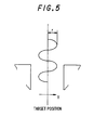
- Fig. 5 is an explanation drawing on a positional prediction-based control of a lowering collision avoidance device in accordance with an embodiment of the invention.
- the lowering of the hoisting accessory i.e. container
- the amount of swing, D is detected (S2, S3).
- the change rate of the amount of swing D is computed (S4), and comparisons between the detected amount of swing D and the threshold level D 1 or D 2 , and the change rate of the amount of swing D are considered as follows:
- Positional prediction means predicting maximum displacement by swing in the current status. In other words, if the current swing continues, the hoisting accessory moves downward in the range of the maximum displacement predicted.
- a threshold level D 3 e.g., ⁇ 110 mm
- the movement of the hoisting accessory is assumed as a simple harmonic motion.
- the amplitude of the hoisting accessory can be calculated from the position of the hoisting accessory (the amount of displacement from the predetermined position), the positional change rate, and the period of vibration as mentioned previously.
- the position of the hoisting accessory can be calculated using the detected values, while the positional change rate can be calculated from the detected values of position at each moment.
- the period of vibration can be calculated from the detected values of the rope length.
- the displacement of the hoisting accessory is represented by the equation 1 ⁇ where X 0 denotes the coordinates of the target position.
- X X 0 + r sin ⁇ t 1
- the displacement X R or X L is a composite vibration comprising a parallel swing and a skew swing, and thus, is not considered to be a simple harmonic motion.
- X R and X L are each reformed into the following equation for reduction into a parallel swing and a skew swing which are considered simple harmonic motions.
- X 1 X R +X L 2 :
- Parallel swing X2 X R - X L 2 : Skew swing
- the displacements X 1 and X 2 can be determined by the method described in (1) above.
- the periods of parallel swing and skew swing are different from each other.
- the functional forms of the original displacements X R and X L can be calculated from X 1 and X 2 by the above-described method.
- X R X 1 + X 2
- X L X 1 - X 2
- E R Max ⁇ X R ⁇
- the calculations for the logics of A and B above are made continuously at each scanning time point from the time when the bottom surface or the suspended container comes to a predetermined height above the entrance of the canyon, for example, 4 m above, or from the time when the trolley comes to a predetermined horizontal position apart from the entrance of the canyon, for example, within 1 meter, to the time when the container arrives at the floor (or is placed on the stack of containers in layers).
- the calculations are made at each scanning time point using the detected values of the rope length.
- the lowering collision avoidance device in accordance with the instant embodiment on a container handling crane, therefore, even if the current swing of the hoisting accessory 10 (i.e., the swing of the container 11) is marked, the lowering speed need not be decreased, when the swing decreases during the lowering of the container 11. Moreover, continued operation can be carried out to the extent that the container 11 will not collide with the adjacent containers 22 and 23. In case a real risk of collision exists, the lowering can be stopped. Thus, the cycle time can be shortened safely.
- a lowering collision avoidance device embodying the present invention is installed on a commercial machine for practical use, and is operated satisfactorily. Thus, its effectiveness has been demonstrated.
- the lowering collision avoidance device in accordance with a first aspect of the invention skillfully utilizes the facts that a carried article, such as a container, suspended by a rope vibrates with a long period like a pendulum and cannot cause abrupt changes in position owing to its inertia.
- the device controls the lowering speed based on the results of comparison between the amount of swing of the hoisting accessory and a threshold level or a plurality of threshold levels, the direction of changes in the amount of swing of the hoisting accessory, and the lowering speed.
- a carried article is lowered, together with the hoisting accessory, to be placed on a stack of containers in layers or on the floor at a site where there are obstacles such as carried articles stacked adjacently in layers.
- the swing of the hoisting accessory decreases during the lowering of the carried article even if the current swing of the hoisting accessory (i.e., the current swing of the carried article) is marked, the lowering speed need not be reduced.
- maximum continued operation can be carried out to the extent that the carried article will not collide with the adjacent obstacle. In case a real risk of collision exists, the lowering of the carried article can be stopped. This enables the cycle time to be shortened safely.
- a lowering collision avoidance device in accordance with a second aspect of the invention, maximum displacement by the swing of the hoisting accessory is predicted. Based on the results of comparison between the predicted maximum displacement by swing and a predetermined threshold level, the lowering speed is controlled. Thus, collision between the lowered carried article and the adjacent obstacle can be prevented more reliably.
Abstract
Description
where
- Vset:
- Command value for lowering speed
- Vc:
- Current value of lowering speed
- Vm:
- Predetermined lowering speed
- ΔV:
- Speed increment at each scanning time point
- I:
- Moment of inertia
- m:
- Weight
- L:
- Rope length
- d:
- Distance between fulcrums
Let
- XR:
- Measured value of displacement by right camera
- XL:
- Measured value of displacement by left camera
- ER:
- Maximum predicted displacement measured by right camera
- EL:
- Maximum predicted displacement measured by left camera
Claims (2)
- A lowering collision avoidance device of a crane, said crane comprising a hoisting/lowering drive motor, a hoisting/lowering device driven by the hoisting/lowering drive motor, a rope taken up or paid out by the hoisting/lowering device, and a hoisting accessory suspended from the hoisting/lowering device via the rope and hoisted or lowered by the hoisting/lowering device, said crane lowering a carried article held by the hoisting accessory, together with the hoisting accessory, to a target position in a stack of other carried articles or to a floor position, said lowering collision avoidance device being adapted to prevent the collision of the carried article during lowering with obstacles such as the other carried articles stacked in layers adjacent to the target position,said lowering collision avoidance device comprising:a hoisting accessory swing detector for detecting the swing of the hoisting accessory;a speed detector for detecting the lowering speed of the carried article; anda controller for controlling the hoisting/lowering drive motor to control the lowering speed of the carried article, said controller performing its control action based on the results of comparison between the amount of swing of the hoisting accessory detected by said hoisting accessory swing detector and a predetermined threshold level or a plurality of predetermined threshold levels; the direction of changes in the amount of swing computed based on the amount of swing of the hoisting accessory; and the lowering speed detected by said speed detector.
- The lowering collision avoidance device of a crane as recited in claim 1, whereina rope length detector is provided for detecting the length of the rope, andsaid controller predicts maximum displacement by swing of the hoisting accessory based on the amount of swing of the hoisting accessory detected by said hoisting accessory swing detector, the positional change rate of the hoisting accessory computed based on the amount of swing of the hoisting accessory, and the period of vibration of the hoisting accessory computed from the rope length detected by said rope length detector, and said controller controls the hoisting/lowering drive motor based on the results of comparison between the predicted maximum displacement by swing and a predetermined threshold level, thereby controlling the lowering speed of the carried article.
Applications Claiming Priority (3)
| Application Number | Priority Date | Filing Date | Title |
|---|---|---|---|
| JP32657596A JP3150636B2 (en) | 1996-12-06 | 1996-12-06 | Crane lowering collision prevention device |
| JP326575/96 | 1996-12-06 | ||
| JP32657596 | 1996-12-06 |
Publications (2)
| Publication Number | Publication Date |
|---|---|
| EP0846648A1 true EP0846648A1 (en) | 1998-06-10 |
| EP0846648B1 EP0846648B1 (en) | 2002-07-24 |
Family
ID=18189348
Family Applications (1)
| Application Number | Title | Priority Date | Filing Date |
|---|---|---|---|
| EP97309771A Expired - Lifetime EP0846648B1 (en) | 1996-12-06 | 1997-12-04 | Apparatus for controlling article-lowering operations of a crane |
Country Status (6)
| Country | Link |
|---|---|
| US (1) | US5967347A (en) |
| EP (1) | EP0846648B1 (en) |
| JP (1) | JP3150636B2 (en) |
| DE (1) | DE69714196T2 (en) |
| HK (1) | HK1010531A1 (en) |
| SG (1) | SG67451A1 (en) |
Cited By (5)
| Publication number | Priority date | Publication date | Assignee | Title |
|---|---|---|---|---|
| EP0979796A1 (en) * | 1998-08-10 | 2000-02-16 | Siemens Aktiengesellschaft | Device and method for the determination of the two-dimensional sway and /or the rotation of a crane load |
| EP2119661A3 (en) * | 2008-05-14 | 2012-05-09 | Westfalia Intralogistic GmbH | Device for measuring a horizontal deflection of a load bearer swinging on support ropes |
| CN109733992A (en) * | 2019-03-07 | 2019-05-10 | 浙江东川自动化科技有限公司 | A kind of erecting equipment system and its control method |
| CN110885009A (en) * | 2019-12-16 | 2020-03-17 | 南通大学 | Anticollision bridge crane |
| CN111704038A (en) * | 2020-07-13 | 2020-09-25 | 大连理工大学 | Bridge crane path planning method considering obstacle avoidance |
Families Citing this family (19)
| Publication number | Priority date | Publication date | Assignee | Title |
|---|---|---|---|---|
| CA2255111C (en) * | 1997-12-05 | 2004-11-23 | Grove U.S. L.L.C. | Aerial work platform with pothole and/or obstacle detection and avoidance system |
| JP4493120B2 (en) * | 1998-10-09 | 2010-06-30 | Ihi運搬機械株式会社 | RMG crane steady rest operation method |
| JP2002104771A (en) * | 2000-07-25 | 2002-04-10 | Inst Of Physical & Chemical Res | Container position detector |
| US6936820B2 (en) * | 2002-04-26 | 2005-08-30 | Bartlett Support Systems, Inc. | Crane mounted cargo container inspection apparatus and method |
| US20050173364A1 (en) * | 2002-07-25 | 2005-08-11 | Siemens Aktiengesellschaft | Method for operating a container crane |
| DE10233875B4 (en) * | 2002-07-25 | 2008-08-14 | Siemens Ag | Crane system, in particular container crane |
| DE10245970B4 (en) * | 2002-09-30 | 2008-08-21 | Siemens Ag | Method and device for detecting a load of a hoist |
| US20040254728A1 (en) * | 2002-10-25 | 2004-12-16 | Poropat George Vladimir | Collision warning system and method |
| US7721967B2 (en) * | 2004-08-13 | 2010-05-25 | Arcelormittal Dofasco Inc. | Remote crane bar code system |
| KR20110123928A (en) * | 2010-05-10 | 2011-11-16 | 한국과학기술원 | Trolley assembly for container crane |
| DE102012004802A1 (en) * | 2012-03-09 | 2013-09-12 | Liebherr-Werk Nenzing Gmbh | Crane control with distribution of a kinematically limited size of the hoist |
| US9102055B1 (en) * | 2013-03-15 | 2015-08-11 | Industrial Perception, Inc. | Detection and reconstruction of an environment to facilitate robotic interaction with the environment |
| SG10201608235YA (en) * | 2015-10-05 | 2017-05-30 | Keppel Offshore & Marine Technology Ct Pte Ltd | System and method for guiding cargo transfer between two bodies |
| JP7180966B2 (en) | 2016-01-29 | 2022-11-30 | マニタウォック クレイン カンパニーズ, エルエルシー | visual outrigger monitoring system |
| US11130658B2 (en) | 2016-11-22 | 2021-09-28 | Manitowoc Crane Companies, Llc | Optical detection and analysis of a counterweight assembly on a crane |
| US10843905B2 (en) * | 2017-04-04 | 2020-11-24 | Summation Labs, LLC | Systems and methods for slung load stabilization |
| EP3461783B1 (en) * | 2017-09-29 | 2019-11-13 | B&R Industrial Automation GmbH | Lifting device and method for controlling a lifting device |
| CN113582016A (en) * | 2020-04-30 | 2021-11-02 | 西门子股份公司 | Method, device and system for controlling crane and storage medium |
| CN113173505B (en) * | 2021-05-11 | 2023-11-14 | 宁波梅东集装箱码头有限公司 | Automatic bottom opening stacking method and system for gantry crane storage yard, storage medium and gantry crane |
Citations (4)
| Publication number | Priority date | Publication date | Assignee | Title |
|---|---|---|---|---|
| US5048703A (en) * | 1988-05-18 | 1991-09-17 | Tax Ingenieurgesellschaft Mbh | Container crane installation |
| EP0596330A1 (en) * | 1992-11-03 | 1994-05-11 | Siemens Aktiengesellschaft | Arrangement for measuring crane load oscillations |
| DE29510031U1 (en) * | 1995-06-21 | 1995-10-26 | Noell Gmbh | Device for the precise positioning and stacking of containers |
| GB2295596A (en) * | 1994-11-30 | 1996-06-05 | Mitsubishi Heavy Ind Ltd | Detecting deflection of a suspended load |
Family Cites Families (2)
| Publication number | Priority date | Publication date | Assignee | Title |
|---|---|---|---|---|
| JP2666959B2 (en) * | 1988-05-07 | 1997-10-22 | 新日本製鐵株式会社 | Sway control method of suspension type crane |
| JPH04122299A (en) * | 1990-09-13 | 1992-04-22 | Taisei Corp | Futon (japanese mattress) driving device |
-
1996
- 1996-12-06 JP JP32657596A patent/JP3150636B2/en not_active Expired - Lifetime
-
1997
- 1997-12-04 EP EP97309771A patent/EP0846648B1/en not_active Expired - Lifetime
- 1997-12-04 DE DE69714196T patent/DE69714196T2/en not_active Expired - Lifetime
- 1997-12-04 US US08/985,241 patent/US5967347A/en not_active Expired - Fee Related
- 1997-12-05 SG SG1997004325A patent/SG67451A1/en unknown
-
1998
- 1998-11-04 HK HK98111729A patent/HK1010531A1/en not_active IP Right Cessation
Patent Citations (4)
| Publication number | Priority date | Publication date | Assignee | Title |
|---|---|---|---|---|
| US5048703A (en) * | 1988-05-18 | 1991-09-17 | Tax Ingenieurgesellschaft Mbh | Container crane installation |
| EP0596330A1 (en) * | 1992-11-03 | 1994-05-11 | Siemens Aktiengesellschaft | Arrangement for measuring crane load oscillations |
| GB2295596A (en) * | 1994-11-30 | 1996-06-05 | Mitsubishi Heavy Ind Ltd | Detecting deflection of a suspended load |
| DE29510031U1 (en) * | 1995-06-21 | 1995-10-26 | Noell Gmbh | Device for the precise positioning and stacking of containers |
Cited By (6)
| Publication number | Priority date | Publication date | Assignee | Title |
|---|---|---|---|---|
| EP0979796A1 (en) * | 1998-08-10 | 2000-02-16 | Siemens Aktiengesellschaft | Device and method for the determination of the two-dimensional sway and /or the rotation of a crane load |
| EP2119661A3 (en) * | 2008-05-14 | 2012-05-09 | Westfalia Intralogistic GmbH | Device for measuring a horizontal deflection of a load bearer swinging on support ropes |
| CN109733992A (en) * | 2019-03-07 | 2019-05-10 | 浙江东川自动化科技有限公司 | A kind of erecting equipment system and its control method |
| CN109733992B (en) * | 2019-03-07 | 2023-10-20 | 浙江东川自动化科技有限公司 | Lifting equipment system and control method thereof |
| CN110885009A (en) * | 2019-12-16 | 2020-03-17 | 南通大学 | Anticollision bridge crane |
| CN111704038A (en) * | 2020-07-13 | 2020-09-25 | 大连理工大学 | Bridge crane path planning method considering obstacle avoidance |
Also Published As
| Publication number | Publication date |
|---|---|
| EP0846648B1 (en) | 2002-07-24 |
| DE69714196T2 (en) | 2003-03-13 |
| JPH10167662A (en) | 1998-06-23 |
| DE69714196D1 (en) | 2002-08-29 |
| SG67451A1 (en) | 1999-09-21 |
| JP3150636B2 (en) | 2001-03-26 |
| HK1010531A1 (en) | 1999-06-25 |
| US5967347A (en) | 1999-10-19 |
Similar Documents
| Publication | Publication Date | Title |
|---|---|---|
| EP0846648B1 (en) | Apparatus for controlling article-lowering operations of a crane | |
| US6182843B1 (en) | Method for the target path correction of a load carrier and load transport apparatus | |
| EP1695936B1 (en) | Apparatus for avoiding collision when lowering container | |
| US4753357A (en) | Container crane | |
| JP4295591B2 (en) | Container collision prevention method and apparatus | |
| CN103998367A (en) | Crane control | |
| EP0846649B1 (en) | Collision avoidance device for a crane | |
| JP2512854B2 (en) | Control system for the cavern lane | |
| JP2001240372A (en) | Control system for cable crane | |
| JP2006256848A (en) | Cargo handling support method and cargo handling support system | |
| JP2973701B2 (en) | Operation control device of container crane | |
| EP0841295B1 (en) | Suspended load steadying/positioning control device | |
| KR20200100265A (en) | A system for preventing collision between tower cranes using relative velocity and absolute velocity and a method of preventing collision between tower cranes using the same | |
| JP3241591B2 (en) | Crane control method | |
| CN112512953A (en) | Crane and crane control method | |
| JP2577127B2 (en) | Bucket for cable crane | |
| JPH0321478B2 (en) | ||
| KR100280267B1 (en) | Collision avoidance method between mobile devices in raw material yard | |
| JP3244498B2 (en) | Speed control method of trolley for cable crane | |
| KR102499985B1 (en) | Safety system for Accident prevention with Camera | |
| JP2759304B2 (en) | Method and apparatus for controlling wheel load in crane | |
| JP3259415B2 (en) | Travel control device for overhead crane | |
| JPH01313299A (en) | Center rest operation control method for hanging load | |
| JP3242633B2 (en) | How to set operation pattern of suspended load suspended by cable crane | |
| JPH0789691A (en) | Detection of swing angle of suspended load on loading machine |
Legal Events
| Date | Code | Title | Description |
|---|---|---|---|
| PUAI | Public reference made under article 153(3) epc to a published international application that has entered the european phase |
Free format text: ORIGINAL CODE: 0009012 |
|
| 17P | Request for examination filed |
Effective date: 19971219 |
|
| AK | Designated contracting states |
Kind code of ref document: A1 Designated state(s): DE GB |
|
| AX | Request for extension of the european patent |
Free format text: AL;LT;LV;MK;RO;SI |
|
| AKX | Designation fees paid |
Free format text: DE GB |
|
| RBV | Designated contracting states (corrected) |
Designated state(s): DE GB |
|
| 17Q | First examination report despatched |
Effective date: 20010323 |
|
| GRAG | Despatch of communication of intention to grant |
Free format text: ORIGINAL CODE: EPIDOS AGRA |
|
| RTI1 | Title (correction) |
Free format text: APPARATUS FOR CONTROLLING ARTICLE-LOWERING OPERATIONS OF A CRANE |
|
| RTI1 | Title (correction) |
Free format text: APPARATUS FOR CONTROLLING ARTICLE-LOWERING OPERATIONS OF A CRANE |
|
| GRAG | Despatch of communication of intention to grant |
Free format text: ORIGINAL CODE: EPIDOS AGRA |
|
| GRAH | Despatch of communication of intention to grant a patent |
Free format text: ORIGINAL CODE: EPIDOS IGRA |
|
| GRAH | Despatch of communication of intention to grant a patent |
Free format text: ORIGINAL CODE: EPIDOS IGRA |
|
| GRAA | (expected) grant |
Free format text: ORIGINAL CODE: 0009210 |
|
| AK | Designated contracting states |
Kind code of ref document: B1 Designated state(s): DE GB |
|
| REG | Reference to a national code |
Ref country code: GB Ref legal event code: FG4D |
|
| REF | Corresponds to: |
Ref document number: 69714196 Country of ref document: DE Date of ref document: 20020829 |
|
| PLBE | No opposition filed within time limit |
Free format text: ORIGINAL CODE: 0009261 |
|
| STAA | Information on the status of an ep patent application or granted ep patent |
Free format text: STATUS: NO OPPOSITION FILED WITHIN TIME LIMIT |
|
| 26N | No opposition filed |
Effective date: 20030425 |
|
| PGFP | Annual fee paid to national office [announced via postgrant information from national office to epo] |
Ref country code: GB Payment date: 20041201 Year of fee payment: 8 |
|
| PG25 | Lapsed in a contracting state [announced via postgrant information from national office to epo] |
Ref country code: GB Free format text: LAPSE BECAUSE OF NON-PAYMENT OF DUE FEES Effective date: 20051204 |
|
| GBPC | Gb: european patent ceased through non-payment of renewal fee |
Effective date: 20051204 |
|
| PGFP | Annual fee paid to national office [announced via postgrant information from national office to epo] |
Ref country code: DE Payment date: 20101130 Year of fee payment: 14 |
|
| REG | Reference to a national code |
Ref country code: DE Ref legal event code: R119 Ref document number: 69714196 Country of ref document: DE Effective date: 20120703 |
|
| PG25 | Lapsed in a contracting state [announced via postgrant information from national office to epo] |
Ref country code: DE Free format text: LAPSE BECAUSE OF NON-PAYMENT OF DUE FEES Effective date: 20120703 |