EP0846205B1 - Connection system for reinforced composite structures - Google Patents
Connection system for reinforced composite structures Download PDFInfo
- Publication number
- EP0846205B1 EP0846205B1 EP96929020A EP96929020A EP0846205B1 EP 0846205 B1 EP0846205 B1 EP 0846205B1 EP 96929020 A EP96929020 A EP 96929020A EP 96929020 A EP96929020 A EP 96929020A EP 0846205 B1 EP0846205 B1 EP 0846205B1
- Authority
- EP
- European Patent Office
- Prior art keywords
- bladder
- accordance
- wedge
- recess
- shaped
- Prior art date
- Legal status (The legal status is an assumption and is not a legal conclusion. Google has not performed a legal analysis and makes no representation as to the accuracy of the status listed.)
- Expired - Lifetime
Links
- 239000002131 composite material Substances 0.000 title description 2
- 238000000034 method Methods 0.000 claims description 7
- 230000003014 reinforcing effect Effects 0.000 claims description 4
- 230000000295 complement effect Effects 0.000 claims 1
- 239000000463 material Substances 0.000 abstract description 4
- 230000002787 reinforcement Effects 0.000 description 17
- 229920001971 elastomer Polymers 0.000 description 14
- 239000005060 rubber Substances 0.000 description 12
- 239000012528 membrane Substances 0.000 description 8
- 230000008901 benefit Effects 0.000 description 3
- 230000000717 retained effect Effects 0.000 description 3
- 239000004677 Nylon Substances 0.000 description 2
- 210000004712 air sac Anatomy 0.000 description 2
- 238000010276 construction Methods 0.000 description 2
- 239000000806 elastomer Substances 0.000 description 2
- 239000013536 elastomeric material Substances 0.000 description 2
- 239000002184 metal Substances 0.000 description 2
- 229920001778 nylon Polymers 0.000 description 2
- 230000000737 periodic effect Effects 0.000 description 2
- 230000008569 process Effects 0.000 description 2
- 239000000126 substance Substances 0.000 description 2
- 230000009471 action Effects 0.000 description 1
- 230000006835 compression Effects 0.000 description 1
- 238000007906 compression Methods 0.000 description 1
- 238000005260 corrosion Methods 0.000 description 1
- 230000007797 corrosion Effects 0.000 description 1
- 230000008878 coupling Effects 0.000 description 1
- 238000010168 coupling process Methods 0.000 description 1
- 238000005859 coupling reaction Methods 0.000 description 1
- 230000000694 effects Effects 0.000 description 1
- 239000012530 fluid Substances 0.000 description 1
- 230000001788 irregular Effects 0.000 description 1
- 229920003052 natural elastomer Polymers 0.000 description 1
- 229920001194 natural rubber Polymers 0.000 description 1
- 229920003051 synthetic elastomer Polymers 0.000 description 1
- 239000005061 synthetic rubber Substances 0.000 description 1
- 238000011144 upstream manufacturing Methods 0.000 description 1
- XLYOFNOQVPJJNP-UHFFFAOYSA-N water Substances O XLYOFNOQVPJJNP-UHFFFAOYSA-N 0.000 description 1
Images










Classifications
-
- B—PERFORMING OPERATIONS; TRANSPORTING
- B60—VEHICLES IN GENERAL
- B60C—VEHICLE TYRES; TYRE INFLATION; TYRE CHANGING; CONNECTING VALVES TO INFLATABLE ELASTIC BODIES IN GENERAL; DEVICES OR ARRANGEMENTS RELATED TO TYRES
- B60C15/00—Tyre beads, e.g. ply turn-up or overlap
- B60C15/02—Seating or securing beads on rims
- B60C15/0209—Supplementary means for securing the bead
-
- B—PERFORMING OPERATIONS; TRANSPORTING
- B60—VEHICLES IN GENERAL
- B60C—VEHICLE TYRES; TYRE INFLATION; TYRE CHANGING; CONNECTING VALVES TO INFLATABLE ELASTIC BODIES IN GENERAL; DEVICES OR ARRANGEMENTS RELATED TO TYRES
- B60C15/00—Tyre beads, e.g. ply turn-up or overlap
- B60C15/02—Seating or securing beads on rims
-
- E—FIXED CONSTRUCTIONS
- E02—HYDRAULIC ENGINEERING; FOUNDATIONS; SOIL SHIFTING
- E02B—HYDRAULIC ENGINEERING
- E02B7/00—Barrages or weirs; Layout, construction, methods of, or devices for, making same
- E02B7/005—Deformable barrages or barrages consisting of permanently deformable elements, e.g. inflatable, with flexible walls
-
- F—MECHANICAL ENGINEERING; LIGHTING; HEATING; WEAPONS; BLASTING
- F16—ENGINEERING ELEMENTS AND UNITS; GENERAL MEASURES FOR PRODUCING AND MAINTAINING EFFECTIVE FUNCTIONING OF MACHINES OR INSTALLATIONS; THERMAL INSULATION IN GENERAL
- F16B—DEVICES FOR FASTENING OR SECURING CONSTRUCTIONAL ELEMENTS OR MACHINE PARTS TOGETHER, e.g. NAILS, BOLTS, CIRCLIPS, CLAMPS, CLIPS OR WEDGES; JOINTS OR JOINTING
- F16B2200/00—Constructional details of connections not covered for in other groups of this subclass
- F16B2200/50—Flanged connections
- F16B2200/506—Flanged connections bolted or riveted
-
- Y—GENERAL TAGGING OF NEW TECHNOLOGICAL DEVELOPMENTS; GENERAL TAGGING OF CROSS-SECTIONAL TECHNOLOGIES SPANNING OVER SEVERAL SECTIONS OF THE IPC; TECHNICAL SUBJECTS COVERED BY FORMER USPC CROSS-REFERENCE ART COLLECTIONS [XRACs] AND DIGESTS
- Y10—TECHNICAL SUBJECTS COVERED BY FORMER USPC
- Y10T—TECHNICAL SUBJECTS COVERED BY FORMER US CLASSIFICATION
- Y10T428/00—Stock material or miscellaneous articles
- Y10T428/24—Structurally defined web or sheet [e.g., overall dimension, etc.]
-
- Y—GENERAL TAGGING OF NEW TECHNOLOGICAL DEVELOPMENTS; GENERAL TAGGING OF CROSS-SECTIONAL TECHNOLOGIES SPANNING OVER SEVERAL SECTIONS OF THE IPC; TECHNICAL SUBJECTS COVERED BY FORMER USPC CROSS-REFERENCE ART COLLECTIONS [XRACs] AND DIGESTS
- Y10—TECHNICAL SUBJECTS COVERED BY FORMER USPC
- Y10T—TECHNICAL SUBJECTS COVERED BY FORMER US CLASSIFICATION
- Y10T428/00—Stock material or miscellaneous articles
- Y10T428/24—Structurally defined web or sheet [e.g., overall dimension, etc.]
- Y10T428/24174—Structurally defined web or sheet [e.g., overall dimension, etc.] including sheet or component perpendicular to plane of web or sheet
- Y10T428/24182—Inward from edge of web or sheet
Definitions
- This invention relates generally to systems for connecting reinforced composite structures, either to other similar materials or to a variety of support structures. More particularly, this invention relates to inflatable bladder designs. In another aspect, this invention relates to inflatable bladders for use in crest gate systems for dam spillways, for example, where one or more rigid gates are pivotably attached at the top of the spillway structure and are movable to a raised position by inflating the bladder, and for inflatable dams which do not utilize pivotably attached panels.
- Inflatable bladders are known for use on the downstream side of pivotably mounted crest gate panels on a dam spillway to control the height of water behind the crest gate. Such systems are described, for example, in U.S. Patents 4,780,024 and 5,092,707, incorporated herein by reference.
- the inflatable bladder includes an edge portion which is secured to the upper surface of the dam spillway by means of a clamp bolted to the spillway.
- the prior art relies on anchor bolts to carry all or part of the shear load imparted by the clamped membrane to the supporting structure such as a concrete spillway. This results in high anchor bolt stresses and concentrated loads in the concrete where the anchor bolts enter the concrete structure.
- time dependant deformation tends to reduce the clamping force which seals the membranes to each other or to the structure, resulting in leakage or the requirement for periodic bolt retightening.
- Most of the prior art clamping systems rely to varying degrees on friction between the clamped membrane and the clamping system elements.
- an elastomeric inflatable bladder as claimed in claim 1 and a method as claimed in claim 12.
- the edge portions are complementarily shaped and when they are placed against each other they form a sealed edge which fits the inside of the. clamping system.
- the edge portions are firmly secured in a manner such that the attachment force is approximately equal to the internal strength of the reinforcement layers of the bladder.
- the bladder is secured in an elongated recess or channel in the upper surface of a dam spillway. Clamps extend over the recess and are bolted to the spillway to retain the edge portions of the inflatable bladder. When the bladder is inflated, the clamped edge portions remain securely fixed in the recess or channel.
- the strength of the attachment is approximately equal to the internal strength of the bladder itself. In other words, the system of the present invention does not create high stress regions in the rubber or its reinforcement at the clamping location.
- the wedges allow the compressive stresses within the clamping system to impart a tensile load to the reinforcement layers without the effect of accumulating shear stresses layer by layer from the middle of the membranes outward.
- the rubber wedges are well suited to withstand the resulting triaxial compressive stresses.
- the maximum shear stresses are uniformly distributed amongst the wedges and are relatively low within the individual wedges.
- the wedge shaped edges are kept tightly compressed by the action of the hoop tension of the air bladder, thus maintaining the required clamping force for a tight seal as time dependant deformation of the elastomeric assembly occurs.
- This self tightening characteristic eliminates the need for periodic manual tightening of the clamping system.
- the self tightening characteristic also permits reliable leak tight clamping directly to irregular rough concrete spillway surfaces which would not be suitable for conventional clamping means.
- a further advantage of this embodiment is to cause the shear loads to be uniformly distributed across the supporting structure rather than to be concentrated at the anchor bolts.
- a further advantage of this clamping system is that it does not rely on friction or chemical bonding to the clamp components to retain the membrane within the clamp.
- the present invention in fact, functions very well even if all components are lubricated prior to assembly.
- the clamping system of the present invention is thus immune to failure due to time dependant slippage of friction surfaces.
- the inflatable bladder can be surface-mounted to the surface of a desired support structure (e.g., a dam spillway) without the need for forming a recess or channel in the support surface.
- a desired support structure e.g., a dam spillway
- the inflatable bladder may be a segment of a wheel or track system for a vehicle.
- the wedge geometry in this case allows the inflatable segments to be easily inserted into or removed from the ends of dovetail grooves while in the deflated condition. While inflated, the tension in the membranes maintains a tight seal and provides a reliable mechanical connection to the wheel or track segment. Unlike conventional pneumatic tires, damaged segments may be replaced quickly without heavy equipment or the need to jack up the vehicle.
- the inflatable bladder may take the form of a reinforced hose or air spring with flanged ends of wedge shaped cross section incorporating the aforementioned wedges interleaved between reinforcement layers. Said flanged ends may be clamped to each other or to conventional rigid flanges with rigid rings and associated bolting system.
- This embodiment shares the advantages of the aforementioned embodiments including self tightening and high strength. This embodiment also provides complete continuity of the hose liner which optimizes resistance of hose assembly to corrosion and abrasive wear.
- Inflatable bladders which include the unique connection system of this invention are composed of multiple layers of reinforced elastomeric material (e.g. natural or synthetic rubber).
- reinforced elastomeric material e.g. natural or synthetic rubber.
- a preferred reinforced bladder construction is described in copending application Serial No. 08/490,643, filed June 15, 1995, incorporated herein by reference.
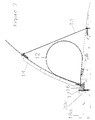
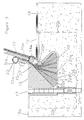
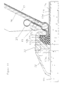
- FIGS 1-4 there is illustrated one embodiment of a crest gate spillway system is shown affixed to the upper surface 18a of a concrete spillway 18.
- the weldment 20, stiffened by ribs 20C, is embedded in the spillway and secured by anchor bolts 17, 17a.
- the downstream side of the weldment 20 is preferably angled forwardly toward the upstream side of the weldment in a manner such that the top opening into the recess or channel is narrower than the base of the channel.
- a hinge flap portion 22 is preferably included which includes an upper section 22a and a wedge-shaped lower section 22b.
- the upper section 22a is secured to the lower end 14a of gate panel 14 by means of bolts 15, 15a.
- the lower section 22b is retained in the recess or channel by means of clamp 16, as shown for example in Figure 3.
- the hinge flap portion 22 is typically composed of a reinforced vulcanized, flexible elastomeric material such as rubber. It is capable of flexing indefinitely.
- the upper edge of the flap preferably includes an incompressible insert 23.
- the hinge flap preferably includes a first reinforcement member comprising a bias ply tire cord reinforcement layer oriented at 45 degrees relative to the gate pivot axis extending from the middle of the large end 22d of the wedge assembly to and around the incompressible insert 23 (e.g. nylon rod) and terminating adjacent to the beginning point at the large edge of the wedge assembly and a straight ply of reinforcement beginning at the upper corner of the large end of the wedge assembly, extending to and around the nylon rod insert and then extending back to the lower corner of the large end of the wedge assembly.
- a first reinforcement member comprising a bias ply tire cord reinforcement layer oriented at 45 degrees relative to the gate pivot axis extending from the middle of the large end 22d of the wedge assembly to and around the incompressible insert 23 (e
- Wedges 22c and 22f are integrally vulcanized between the inner bias plies 22d and each of the outer longitudinal plies 22g. In this manner, the shear stresses in the wedges are made uniform and a load path is provded by the bias plies around the bolt holes 15a which are required for attachment to the gate panel 14.
- the lower edge 14a of the gate panel is preferably rounded, as shown in Figure 3, and has a diameter at least as great as (and preferably greater) than the thickness of the gate panel this rounded edge minimizes the stress on the flap portion 22 and also on the portion of the bladder 12 with is in contact with the edge 14a.
- corner 20a of the weldment 20 is rounded so as to minimize stress on the rubber portion of the bladder which is in contact with corner 20a.
- a flexible retaining strap 13 is preferably secured at one end to the spillway and at its opposite end to the upper end of the gate panel 14. The strap prevents the gate panel from tipping too far forwardly.
- Air can be supplied to the bladder 12 through ductwork 24.
- the ductwork is embedded in the upper surface of the dam spillway.
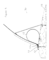
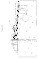
- FIG. 5-8 Another embodiment of inflatable bladder system 30 is illustrated in Figures 5-8.
- this embodiment there is no recess or channel in the dam spillway for retaining the edge portion of the inflatable bladder. Rather, the wedge-shaped edge portions 12a and 12b of the bladder are retained by means of a clamping means 32 which is secured to the upper surface of the spillway by bolts 33.
- the clamp 32 includes a leg portion 32a which projects downwardly. The wedge-shaped edge portions of the bladder and the flap 22 are captured and retained between the clamp and the upper surface of the dam spillway.
- Ductwork 34 in the spillway supplies air to the bladder, when desired.
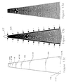
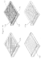
- Fig.13a, 13b, and 13c illustrate the manner in which the tensile loads 47 are carried by the compressive forces 48 imparted by the clamp system, without the need to transmit shear loads to adjacent layers.
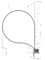
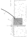
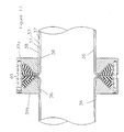
- FIG. 14 Another embodiment of the inflatable bladder system for use as a rubber dam is illustrated in Fig. 14, Fig 14a, Fig 15, and Fig. 16.
- the function of the illustrated clamping systems as used for rubber dams is similar to those described for the systems which include a pivotable gate panel.
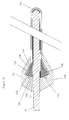
- Air bladders with wedge shaped edges can be manufactured by laying up in sequence, referring to Fig 10 and Fig 21; an innerliner 12c, the various layers of reinforcement (e.g., skimmed tire cord oriented at -45 degrees 12d, 0 degrees 12f, and +45 degrees 12h) followed by a weather resistant cover flat rectangular mandrel 34 with radiused edge 34a (The radiused edges reduce tensile stress concentrations in the inflated bladder).
- extruded wedges 12e, 12g, 12j, and 12k of uncured high durometer rubber are inserted between adjacent edges of the layers of reinforcement.
- Mold pieces 35a and 35b with wedge shaped cavities are then secured to the mandrel 34 to control the precise shape of the wedge shaped bladder edges.
- the mold pieces may incorporate means to feed in additional uncured rubber material during the cure cycle in order to eliminate unintended voids created during the assembly process.
- the assembly with mold pieces in place may then be cured by conventional means in a press or autoclave.
- the wedge angles are preferably chosen to provide equal wedge angles between reinforcement layers and to create a total wedge angle equal to the clamping system internal angle.
- the length of the wedges and the corresponding shear area in contact with the reinforcing cord layers is selected such that the bond strength times the bond area equals or exceeds the bond length needed to exceed the tensile strength of the cord.
- Wedges are most conveniently made of a high durometer elastomer capable of forming high strength bond to each of the reinforcement layers.
- the clamping system and corresponding multi-ply reinforcement with interleaved wedges herein described has utility in many important industrial applications including the coupling of large diameter hoses as illustrated in Fig. 17, the attachment of air springs, the attachment of inflatable pontoons and the construction of segmental tires as illustrated in Fig. 18, 18a.
- the hose connection assembly illustrated in Fig 17 is comprised of a liner 36, various layers of reinforcement 37, a cover 38, clamping rings 39a and 39b and bolts 40.
- the recesses in the clamping rings are shaped to match the clamped wedge shaped flanges of the hoses. In this manner a tight seal is created with no metal parts exposed to the fluid carried by the hose and the strength of the connection closely approximates the strength of the hose reinforcement itself. Additionally, no elastomer to metal chemical bonds are required in order to secure the hose
- a segmental tire can be constructed using the wedge attachment means described herein.
- Tire segments 42 may be secured in a rim incorporating a plurality of dovetail slots into which the segments are secured by the process of inflation.
- Inflation lines 44 may be clamped directly into the clamped edge of the segments.
- a molded tread 42b may be provided to create a circular perimeter.
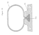
- inflatable bladders 46 may be readily secured to the links 45 of a vehicle track system for example, by providing dovetail slots 45a for this purpose in each link.
Landscapes
- Engineering & Computer Science (AREA)
- Mechanical Engineering (AREA)
- Structural Engineering (AREA)
- General Engineering & Computer Science (AREA)
- Civil Engineering (AREA)
- Barrages (AREA)
- Laminated Bodies (AREA)
- Moulds For Moulding Plastics Or The Like (AREA)
- Joining Of Building Structures In Genera (AREA)
- Clamps And Clips (AREA)
- Rigid Pipes And Flexible Pipes (AREA)
- Protection Of Pipes Against Damage, Friction, And Corrosion (AREA)
- Forms Removed On Construction Sites Or Auxiliary Members Thereof (AREA)
- Mutual Connection Of Rods And Tubes (AREA)
- Heating, Cooling, Or Curing Plastics Or The Like In General (AREA)
- Lining Or Joining Of Plastics Or The Like (AREA)
Abstract
Description
The clamping means of the prior art is adequate for systems of limited height but becomes ineffective and uneconomic in higher systems subject to greater loads. High loads require multiple plies of reinforcement. Conventional clamping means transmit shear loads from the inner plies of reinforcement to the clamping system through the outer plies of reinforcement, resulting in disproportionally high shear loads in the outer layers of the reinforced membrane. Additionally, the prior art relies on anchor bolts to carry all or part of the shear load imparted by the clamped membrane to the supporting structure such as a concrete spillway. This results in high anchor bolt stresses and concentrated loads in the concrete where the anchor bolts enter the concrete structure. In prior art designs, time dependant deformation (creep or compression set) tends to reduce the clamping force which seals the membranes to each other or to the structure, resulting in leakage or the requirement for periodic bolt retightening. Most of the prior art clamping systems rely to varying degrees on friction between the clamped membrane and the clamping system elements.
Claims (14)
- An elastomeric inflatable bladder (12) for inflatable dams including attachment means (12e, 12g, 12j, 12k) characterised by said bladder (12) comprising a plurality of reinforced elastomeric sheets layered on top of one another so as to create an inflatable envelope having opposing edges defining an opening, at least one of said edges being wedge-shaped (12a, 12b) and forming said attachment means integral therewith; and said wedge-shaped edge comprising at least one elastomeric wedge member (12e, 12g) between adjacent layers of said reinforced sheets containing reinforcing cords (12d, 12f, 12h); wherein said wedge member has a triangular cross-section and includes opposite side surfaces bonded to said adjacent layers.
- A bladder in accordance with claim 1, wherein said wedges (12a, 12b) comprise rigid wedges which include opposite side surfaces bonded to reinforced layers of said elastomeric sheets.
- A bladder in accordance with claim 1, wherein there are two said edge portions which are complementarily shaped.
- A bladder as claimed in claim 1 in combination with an elongated link (45) having an upper surface with a channel (45a) therein, wherein said attachment means (12e, 12g, 12j, 12k) is attached in said channel and extending above said upper surface.
- A bladder as claimed in any preceding claim in combination with a support structure (16, 32) comprising a support surface or clamping means having an elongated recess therein; wherein said opposing edge portions of said bladder are secured in said elongated recess.
- A bladder in accordance with claim 5, wherein said clamping means (32) comprises clamps which extend over said recess, and anchor bolts (33) which are anchored in said support surface and which retain said clamps in a fixed position.
- A bladder in accordance with claim 5 or 6, wherein said support surface comprises a concrete spillway.
- A bladder in accordance with claim 7, wherein said spillway includes an upper surface, and wherein said recess extends along said upper surface.
- A bladder in accordance with any of claims 5 to 8, further comprising a gate panel (14) having a leading edge which is hinged to said bladder (12) adjacent said opposing edge portions of said bladder.
- A bladder in accordance with claim 9, wherein said bladder (12) further includes a wedge-shaped flap portion (22), and wherein said leading edge of said gate panel (14) is secured to said flap portion.
- A method for attaching the inflatable bladder (12) as defined in claim 1 to a support structure (16, 32), comprising the steps of:(a) providing an elastomeric inflatable bladder (12) comprising a plurality of reinforced elastomeric sheets layered on top of one another so as to create an inflatable envelope having opposing edges defining an opening, at least one of said edges being wedge-shaped (12a, 12b) to form an integral attachment means (12e, 12g, 12j, 12k);(b) providing an elongated recess in said support structure; and(c) securing said attachment means (12e, 12g, 12j, 12k) of said bladder in said recess.
- A method in accordance with claim 11, wherein there are two said opposing edges which are wedge-shaped.
- A method in accordance with claim 12, wherein said opposing edge portions are secured in said recess by means of a wedge-shaped clamp (32).
- A method in accordance with claim 13, wherein said recess has a cross-sectional configuration which is complementary to the cross-sectional configuration of said edge portions and said clamp.
Applications Claiming Priority (3)
| Application Number | Priority Date | Filing Date | Title |
|---|---|---|---|
| US518620 | 1995-08-23 | ||
| US08/518,620 US5709502A (en) | 1995-08-23 | 1995-08-23 | Connection system for reinforced composite structures |
| PCT/US1996/013633 WO1997008393A1 (en) | 1995-08-23 | 1996-08-21 | Connection system for reinforced composite structures |
Publications (2)
| Publication Number | Publication Date |
|---|---|
| EP0846205A1 EP0846205A1 (en) | 1998-06-10 |
| EP0846205B1 true EP0846205B1 (en) | 2001-12-19 |
Family
ID=24064749
Family Applications (1)
| Application Number | Title | Priority Date | Filing Date |
|---|---|---|---|
| EP96929020A Expired - Lifetime EP0846205B1 (en) | 1995-08-23 | 1996-08-21 | Connection system for reinforced composite structures |
Country Status (12)
| Country | Link |
|---|---|
| US (3) | US5709502A (en) |
| EP (1) | EP0846205B1 (en) |
| JP (2) | JP3665647B2 (en) |
| KR (2) | KR100600115B1 (en) |
| CN (1) | CN1051127C (en) |
| AT (1) | ATE211204T1 (en) |
| AU (1) | AU717818B2 (en) |
| CA (1) | CA2229213C (en) |
| DE (1) | DE69618209T2 (en) |
| ES (1) | ES2165519T3 (en) |
| IN (1) | IN190515B (en) |
| WO (1) | WO1997008393A1 (en) |
Cited By (1)
| Publication number | Priority date | Publication date | Assignee | Title |
|---|---|---|---|---|
| US9308704B2 (en) | 2013-02-18 | 2016-04-12 | The Boeing Company | Elastomeric bladder system |
Families Citing this family (28)
| Publication number | Priority date | Publication date | Assignee | Title |
|---|---|---|---|---|
| WO2001051714A1 (en) * | 2000-01-12 | 2001-07-19 | Akio Iida | Elevating gate |
| US6678937B2 (en) * | 2000-10-26 | 2004-01-20 | Kimball Physics, Inc. | Alternative method for sealing all-metal vacuum joints |
| JP4394439B2 (en) | 2001-07-09 | 2010-01-06 | オバーメイヤー,ヘンリー,ケイ. | Water control gate and its actuator |
| GB0127216D0 (en) * | 2001-11-13 | 2002-01-02 | Univ Edinburgh | Watertight gate mechanism |
| EP1756641A1 (en) * | 2004-05-03 | 2007-02-28 | Carl Zeiss SMT AG | Optical assembly structure comprising a connecting body with thermal expansion compensation means |
| EA010821B1 (en) * | 2004-08-31 | 2008-12-30 | Хенри К. Обермейер | High strength joining system for fiber reinforced composites |
| US7422392B2 (en) * | 2004-10-06 | 2008-09-09 | Obermeyer Henry K | Water control structure |
| US8079773B2 (en) * | 2005-10-18 | 2011-12-20 | General Electric Company | Methods and apparatus for assembling composite structures |
| DE102005056134B4 (en) * | 2005-11-23 | 2007-09-20 | Autoliv Development Ab | security system |
| KR100578256B1 (en) * | 2006-02-02 | 2006-05-11 | 한국기술개발 주식회사 | Movable beam for river level control |
| KR100865872B1 (en) | 2008-04-24 | 2008-10-29 | 김명진 | Shovel movable beam device |
| CN102071664B (en) * | 2010-12-16 | 2012-11-21 | 江河机电装备工程有限公司 | Room temperature vulcanizing high-strength seamless large-scale rubber air sac and production technology thereof |
| ITMO20120062A1 (en) * | 2012-03-12 | 2013-09-13 | E P Di Provasi Elvino Ambientenerg Ia | PERFECT HYDRAULIC BRIDLE. |
| GB201217245D0 (en) * | 2012-09-27 | 2012-11-07 | Airbus Operations Ltd | A cure tool |
| MX2015005053A (en) * | 2012-10-23 | 2016-04-28 | Eextreme Global Ltd | A retention device. |
| CN103074870B (en) * | 2013-01-28 | 2015-04-08 | 曲振会 | Novel rubber dam body |
| CN103132490A (en) * | 2013-02-19 | 2013-06-05 | 江河机电装备工程有限公司 | Clamping casting device for 1-4m pneumatic shield-shaped gate |
| GB201310299D0 (en) * | 2013-06-10 | 2013-07-24 | Lee Christopher E | Storm inflatable dam deployment system |
| WO2015042616A1 (en) * | 2013-09-23 | 2015-03-26 | Henry Obermeyer | Inflatable article with reduced stress concentrations |
| KR102521621B1 (en) | 2014-07-18 | 2023-04-13 | 헨리 케이 오베르메이어 | Water control gate anchoring system and method |
| CN105714744A (en) * | 2015-06-03 | 2016-06-29 | 浙江海洋学院 | Water stopping dam |
| CN108026708B (en) * | 2015-09-25 | 2020-09-15 | 寺田溥 | Sluice gate |
| US10179282B2 (en) | 2016-02-26 | 2019-01-15 | Impyrium, Inc. | Joystick input apparatus with living hinges |
| ES2845001T3 (en) * | 2016-06-13 | 2021-07-23 | Rsa Protective Tech Llc | Method and system for a retractable retaining wall system |
| US10975538B2 (en) | 2016-06-13 | 2021-04-13 | Rsa Protective Technologies, Llc | Method and system for a retractable floodwall system |
| DK179294B1 (en) * | 2017-03-30 | 2018-04-16 | Steen Olsen Invest Aps | Flood protection |
| JP7812067B2 (en) * | 2021-11-30 | 2026-02-09 | マイクロクラフト株式会社 | Substrate fixing device and printed wiring board inspection device |
| US20250091298A1 (en) * | 2023-09-20 | 2025-03-20 | B/E Aerospace, Inc. | Joints for composite laminated panels and beams |
Family Cites Families (39)
| Publication number | Priority date | Publication date | Assignee | Title |
|---|---|---|---|---|
| US294160A (en) * | 1884-02-26 | Metallic steam-pipe connection | ||
| US1185487A (en) * | 1915-06-25 | 1916-05-30 | Harold K Eastman | Pipe-coupling. |
| US1939872A (en) * | 1932-10-05 | 1933-12-19 | Goodrich Co B F | Coupling for flexible hose |
| US2201684A (en) * | 1937-09-02 | 1940-05-21 | Gen Ceramics Company | Ceramic article |
| GB572932A (en) * | 1943-06-07 | 1945-10-30 | Anglo Iranian Oil Co Ltd | Improvements relating to couplings for flexible tubes or electric cables |
| US2408960A (en) * | 1944-07-25 | 1946-10-08 | Whitehead Bros Rubber Company | Flexible pipe coupling |
| US2919936A (en) * | 1956-01-03 | 1960-01-05 | Curtiss Wright Corp | Metallic lined pipe coupling having a metallic seal |
| FR1166480A (en) * | 1956-11-09 | 1958-11-12 | Kleber Colombes | Pipe with its connecting device and method for manufacturing it |
| US3235291A (en) * | 1963-04-29 | 1966-02-15 | Phillips Petroleum Co | Coupling for a thermoplastic liner in a metal conduit |
| GB1091281A (en) * | 1963-06-19 | 1967-11-15 | Dunlop Rubber Co | Improvements in vehicle supporting and propelling members |
| GB1251205A (en) * | 1968-04-02 | 1971-10-27 | ||
| IT972594B (en) * | 1972-12-20 | 1974-05-31 | Pirelli | PNEUMATIC PUCTA |
| AR202245A1 (en) * | 1974-03-04 | 1975-05-23 | Pirelli | PNEUMATIC WHEEL FOR AUTOMOTIVE VEHICLES |
| AT346875B (en) * | 1974-09-06 | 1978-09-15 | Wurth Anciens Ets Paul | COMPENSATOR CONNECTION BETWEEN TWO REFRACTORY LINED PIPE SECTIONS AND ARTICULATED NOZZLE SOCKETS WITH THESE CONNECTIONS |
| US3975915A (en) * | 1974-10-23 | 1976-08-24 | The Firestone Tire & Rubber Company | Anchor assembly for an inflatable fabric dam |
| FR2318041A1 (en) * | 1975-07-18 | 1977-02-11 | Uniroyal | PNEUMATIC SAFETY BANDAGE FOR VEHICLE WHEELS AND ITS COMPONENT ELEMENTS |
| US4299514A (en) * | 1978-12-06 | 1981-11-10 | Bridgestone Tire Co., Ltd. | Collapsible rubber dam |
| US4330224A (en) * | 1979-03-20 | 1982-05-18 | Bridgestone Tire Company Limited | Collapsible rubber dam installation |
| US4498810A (en) * | 1980-03-06 | 1985-02-12 | Bridgestone Tire Company Limited | Collapsible rubber dam |
| EP0054574B1 (en) * | 1980-12-18 | 1984-07-04 | Schulz & Co. KG | Flange |
| HU183563B (en) * | 1981-09-03 | 1984-05-28 | Taurus Gumiipari Vallalat | High-pressure hose suitable for carrying gases and gas-containing fluids |
| US4649960A (en) * | 1982-04-27 | 1987-03-17 | Hercules Incorporated | Filament wound interlaminate tubular attachment |
| DE3228315C2 (en) * | 1982-07-29 | 1984-07-05 | Kober AG, 8750 Glarus | Sealing device for sealing expansion joints on the building site |
| US4838831A (en) * | 1982-09-30 | 1989-06-13 | The Boeing Company | Coupling for connecting two shafts |
| CA1217668A (en) * | 1983-01-31 | 1987-02-10 | Frank A. Braun | Expansion joint |
| US4647250A (en) * | 1983-04-22 | 1987-03-03 | Howard Ralph H | Canadian flexible dams |
| DE3503194C2 (en) * | 1985-01-31 | 1987-02-19 | Uni-Cardan Ag, 5200 Siegburg | Shaft connection |
| DE3604467A1 (en) * | 1985-08-31 | 1987-03-05 | Agintec Ag | FLANGE CONNECTION |
| GB2184150B (en) * | 1985-10-12 | 1989-11-29 | Bridgestone Corp | Flexible sheet dam |
| JP2688896B2 (en) * | 1987-02-03 | 1997-12-10 | 株式会社ブリヂストン | Damage protection flexible membrane weir |
| US4780024A (en) * | 1987-06-05 | 1988-10-25 | Obermeyer Henry K | Crest gate |
| US4921373A (en) * | 1988-12-07 | 1990-05-01 | Coffey Robert C | Barrier for containing floods |
| JP2717564B2 (en) * | 1989-01-20 | 1998-02-18 | 株式会社ブリヂストン | Rubber dam |
| JP2794216B2 (en) * | 1989-12-28 | 1998-09-03 | 株式会社ブリヂストン | Flexible membrane weir |
| US5092707A (en) * | 1990-10-25 | 1992-03-03 | Obermeyer Henry K | Crest gate operating system |
| US5538360A (en) * | 1992-03-02 | 1996-07-23 | Obermeyer; Henry K. | Crest gate operating system |
| US5713699A (en) * | 1992-03-02 | 1998-02-03 | Obermeyer; Henry K. | Spillway crest gate system and inflatable bladder therefor |
| US5422150A (en) * | 1993-12-23 | 1995-06-06 | Hycomp, Inc. | Substrate clad with fiber-reinforced polymer composite |
| US5716158A (en) * | 1996-08-23 | 1998-02-10 | The Atlantic Group, Inc. | Expandable belt type expansion joint |
-
1995
- 1995-08-23 US US08/518,620 patent/US5709502A/en not_active Expired - Lifetime
-
1996
- 1996-06-14 IN IN1112CA1996 patent/IN190515B/en unknown
- 1996-08-21 KR KR1020057001544A patent/KR100600115B1/en not_active Expired - Lifetime
- 1996-08-21 CA CA002229213A patent/CA2229213C/en not_active Expired - Lifetime
- 1996-08-21 DE DE69618209T patent/DE69618209T2/en not_active Expired - Lifetime
- 1996-08-21 ES ES96929020T patent/ES2165519T3/en not_active Expired - Lifetime
- 1996-08-21 KR KR1019980701305A patent/KR100557025B1/en not_active Expired - Lifetime
- 1996-08-21 CN CN96197535A patent/CN1051127C/en not_active Expired - Lifetime
- 1996-08-21 JP JP51045397A patent/JP3665647B2/en not_active Expired - Lifetime
- 1996-08-21 WO PCT/US1996/013633 patent/WO1997008393A1/en not_active Ceased
- 1996-08-21 AU AU68578/96A patent/AU717818B2/en not_active Expired
- 1996-08-21 EP EP96929020A patent/EP0846205B1/en not_active Expired - Lifetime
- 1996-08-21 AT AT96929020T patent/ATE211204T1/en active
-
1998
- 1998-01-16 US US09/008,014 patent/US6196763B1/en not_active Expired - Lifetime
- 1998-01-16 US US09/008,048 patent/US5948501A/en not_active Expired - Lifetime
-
2005
- 2005-01-13 JP JP2005006460A patent/JP3759153B2/en not_active Expired - Lifetime
Cited By (1)
| Publication number | Priority date | Publication date | Assignee | Title |
|---|---|---|---|---|
| US9308704B2 (en) | 2013-02-18 | 2016-04-12 | The Boeing Company | Elastomeric bladder system |
Also Published As
| Publication number | Publication date |
|---|---|
| AU717818B2 (en) | 2000-04-06 |
| ATE211204T1 (en) | 2002-01-15 |
| CN1051127C (en) | 2000-04-05 |
| EP0846205A1 (en) | 1998-06-10 |
| JP3665647B2 (en) | 2005-06-29 |
| KR20050044795A (en) | 2005-05-12 |
| JPH11511523A (en) | 1999-10-05 |
| KR19990044072A (en) | 1999-06-25 |
| WO1997008393A1 (en) | 1997-03-06 |
| IN190515B (en) | 2003-08-02 |
| US5948501A (en) | 1999-09-07 |
| DE69618209T2 (en) | 2002-08-22 |
| ES2165519T3 (en) | 2002-03-16 |
| CA2229213C (en) | 2007-05-22 |
| KR100557025B1 (en) | 2006-06-21 |
| KR100600115B1 (en) | 2006-07-13 |
| US5709502A (en) | 1998-01-20 |
| CN1199441A (en) | 1998-11-18 |
| MX9801412A (en) | 1998-05-31 |
| AU6857896A (en) | 1997-03-19 |
| CA2229213A1 (en) | 1997-03-06 |
| JP3759153B2 (en) | 2006-03-22 |
| JP2005098110A (en) | 2005-04-14 |
| DE69618209D1 (en) | 2002-01-31 |
| US6196763B1 (en) | 2001-03-06 |
Similar Documents
| Publication | Publication Date | Title |
|---|---|---|
| US5709502A (en) | Connection system for reinforced composite structures | |
| US3857617A (en) | Split chevron track shoes for track belts | |
| US5713699A (en) | Spillway crest gate system and inflatable bladder therefor | |
| EP3615351B1 (en) | Tire with spoke loops | |
| US4889167A (en) | Pipe repair device | |
| KR101066825B1 (en) | Quantity control gates and their actuators | |
| US4241775A (en) | Tires | |
| US20110024008A1 (en) | Tension-based non-pneumatic tire | |
| US5092707A (en) | Crest gate operating system | |
| JP2718682B2 (en) | Vehicle belted tires | |
| FI61841B (en) | KOMPINATION AV DAECK OCH HJULFAELG | |
| JPS59158796A (en) | Hydraulic jack and manufacture thereof | |
| MXPA98001412A (en) | Connection system for composite structures reforza | |
| JP2002038503A (en) | Flexible joint, joint structure using the same, and construction method of submerged tunnel | |
| US4323102A (en) | Dirt seal for removable rubber belts | |
| US4046428A (en) | Traction shoe seal | |
| CA1264469A (en) | Pneumatic lift jack | |
| JPS592240Y2 (en) | Tail seal for shield excavator | |
| TW305903B (en) | An elastomeric inflatable bladder, a combination and a method for attaching the bladder to a support structure | |
| CN120693248A (en) | System and method for making a non-pneumatic tire | |
| EP0025183A2 (en) | Track belt with flexible track shoes and/or anchor plates | |
| CN118488898A (en) | Non-pneumatic tire and system and method of making same | |
| JPS63280619A (en) | Cap mounting structure for flat rubber bag | |
| JPH04841B2 (en) | ||
| JPH10292315A (en) | Road joint-gap reinforcing material |
Legal Events
| Date | Code | Title | Description |
|---|---|---|---|
| PUAI | Public reference made under article 153(3) epc to a published international application that has entered the european phase |
Free format text: ORIGINAL CODE: 0009012 |
|
| 17P | Request for examination filed |
Effective date: 19980220 |
|
| AK | Designated contracting states |
Kind code of ref document: A1 Designated state(s): AT BE CH DE DK ES FI FR GB GR IE IT LI LU NL PT SE |
|
| 17Q | First examination report despatched |
Effective date: 19990914 |
|
| GRAG | Despatch of communication of intention to grant |
Free format text: ORIGINAL CODE: EPIDOS AGRA |
|
| GRAG | Despatch of communication of intention to grant |
Free format text: ORIGINAL CODE: EPIDOS AGRA |
|
| GRAG | Despatch of communication of intention to grant |
Free format text: ORIGINAL CODE: EPIDOS AGRA |
|
| GRAH | Despatch of communication of intention to grant a patent |
Free format text: ORIGINAL CODE: EPIDOS IGRA |
|
| GRAH | Despatch of communication of intention to grant a patent |
Free format text: ORIGINAL CODE: EPIDOS IGRA |
|
| GRAA | (expected) grant |
Free format text: ORIGINAL CODE: 0009210 |
|
| AK | Designated contracting states |
Kind code of ref document: B1 Designated state(s): AT BE CH DE DK ES FI FR GB GR IE IT LI LU NL PT SE |
|
| PG25 | Lapsed in a contracting state [announced via postgrant information from national office to epo] |
Ref country code: GR Free format text: LAPSE BECAUSE OF FAILURE TO SUBMIT A TRANSLATION OF THE DESCRIPTION OR TO PAY THE FEE WITHIN THE PRESCRIBED TIME-LIMIT Effective date: 20011219 Ref country code: FI Free format text: LAPSE BECAUSE OF FAILURE TO SUBMIT A TRANSLATION OF THE DESCRIPTION OR TO PAY THE FEE WITHIN THE PRESCRIBED TIME-LIMIT Effective date: 20011219 Ref country code: BE Free format text: LAPSE BECAUSE OF FAILURE TO SUBMIT A TRANSLATION OF THE DESCRIPTION OR TO PAY THE FEE WITHIN THE PRESCRIBED TIME-LIMIT Effective date: 20011219 |
|
| REF | Corresponds to: |
Ref document number: 211204 Country of ref document: AT Date of ref document: 20020115 Kind code of ref document: T |
|
| REG | Reference to a national code |
Ref country code: CH Ref legal event code: EP |
|
| REG | Reference to a national code |
Ref country code: GB Ref legal event code: IF02 |
|
| REG | Reference to a national code |
Ref country code: IE Ref legal event code: FG4D |
|
| REF | Corresponds to: |
Ref document number: 69618209 Country of ref document: DE Date of ref document: 20020131 |
|
| REG | Reference to a national code |
Ref country code: CH Ref legal event code: NV Representative=s name: BOVARD AG PATENTANWAELTE |
|
| REG | Reference to a national code |
Ref country code: ES Ref legal event code: FG2A Ref document number: 2165519 Country of ref document: ES Kind code of ref document: T3 |
|
| PG25 | Lapsed in a contracting state [announced via postgrant information from national office to epo] |
Ref country code: PT Free format text: LAPSE BECAUSE OF FAILURE TO SUBMIT A TRANSLATION OF THE DESCRIPTION OR TO PAY THE FEE WITHIN THE PRESCRIBED TIME-LIMIT Effective date: 20020319 Ref country code: DK Free format text: LAPSE BECAUSE OF FAILURE TO SUBMIT A TRANSLATION OF THE DESCRIPTION OR TO PAY THE FEE WITHIN THE PRESCRIBED TIME-LIMIT Effective date: 20020319 |
|
| PG25 | Lapsed in a contracting state [announced via postgrant information from national office to epo] |
Ref country code: LU Free format text: LAPSE BECAUSE OF NON-PAYMENT OF DUE FEES Effective date: 20020821 Ref country code: IE Free format text: LAPSE BECAUSE OF NON-PAYMENT OF DUE FEES Effective date: 20020821 |
|
| PLBE | No opposition filed within time limit |
Free format text: ORIGINAL CODE: 0009261 |
|
| STAA | Information on the status of an ep patent application or granted ep patent |
Free format text: STATUS: NO OPPOSITION FILED WITHIN TIME LIMIT |
|
| 26N | No opposition filed | ||
| REG | Reference to a national code |
Ref country code: IE Ref legal event code: MM4A |
|
| REG | Reference to a national code |
Ref country code: CH Ref legal event code: PFA Owner name: OBERMEYER, HENRY K Free format text: OBERMEYER, HENRY K#303 WEST COUNTY ROAD 74#WELLINGTON, CO 80549 (US) -TRANSFER TO- OBERMEYER, HENRY K#303 WEST COUNTY ROAD 74#WELLINGTON, CO 80549 (US) |
|
| REG | Reference to a national code |
Ref country code: FR Ref legal event code: PLFP Year of fee payment: 20 |
|
| PGFP | Annual fee paid to national office [announced via postgrant information from national office to epo] |
Ref country code: NL Payment date: 20150809 Year of fee payment: 20 |
|
| PGFP | Annual fee paid to national office [announced via postgrant information from national office to epo] |
Ref country code: ES Payment date: 20150810 Year of fee payment: 20 Ref country code: DE Payment date: 20150818 Year of fee payment: 20 Ref country code: GB Payment date: 20150819 Year of fee payment: 20 Ref country code: CH Payment date: 20150811 Year of fee payment: 20 |
|
| PGFP | Annual fee paid to national office [announced via postgrant information from national office to epo] |
Ref country code: FR Payment date: 20150811 Year of fee payment: 20 Ref country code: AT Payment date: 20150810 Year of fee payment: 20 Ref country code: SE Payment date: 20150811 Year of fee payment: 20 |
|
| PGFP | Annual fee paid to national office [announced via postgrant information from national office to epo] |
Ref country code: IT Payment date: 20150827 Year of fee payment: 20 |
|
| REG | Reference to a national code |
Ref country code: DE Ref legal event code: R071 Ref document number: 69618209 Country of ref document: DE |
|
| REG | Reference to a national code |
Ref country code: NL Ref legal event code: MK Effective date: 20160820 |
|
| REG | Reference to a national code |
Ref country code: CH Ref legal event code: PL |
|
| REG | Reference to a national code |
Ref country code: GB Ref legal event code: PE20 Expiry date: 20160820 |
|
| REG | Reference to a national code |
Ref country code: SE Ref legal event code: EUG |
|
| REG | Reference to a national code |
Ref country code: AT Ref legal event code: MK07 Ref document number: 211204 Country of ref document: AT Kind code of ref document: T Effective date: 20160821 |
|
| PG25 | Lapsed in a contracting state [announced via postgrant information from national office to epo] |
Ref country code: GB Free format text: LAPSE BECAUSE OF EXPIRATION OF PROTECTION Effective date: 20160820 |
|
| REG | Reference to a national code |
Ref country code: ES Ref legal event code: FD2A Effective date: 20161128 |
|
| PG25 | Lapsed in a contracting state [announced via postgrant information from national office to epo] |
Ref country code: ES Free format text: LAPSE BECAUSE OF EXPIRATION OF PROTECTION Effective date: 20160822 |