EP0845615B1 - Clutch release assembly - Google Patents
Clutch release assembly Download PDFInfo
- Publication number
- EP0845615B1 EP0845615B1 EP97402853A EP97402853A EP0845615B1 EP 0845615 B1 EP0845615 B1 EP 0845615B1 EP 97402853 A EP97402853 A EP 97402853A EP 97402853 A EP97402853 A EP 97402853A EP 0845615 B1 EP0845615 B1 EP 0845615B1
- Authority
- EP
- European Patent Office
- Prior art keywords
- diaphragm
- deformation
- fingers
- finger
- operating element
- Prior art date
- Legal status (The legal status is an assumption and is not a legal conclusion. Google has not performed a legal analysis and makes no representation as to the accuracy of the status listed.)
- Expired - Lifetime
Links
- 238000005096 rolling process Methods 0.000 claims description 19
- 239000000463 material Substances 0.000 claims description 15
- 239000002184 metal Substances 0.000 claims description 8
- 230000015572 biosynthetic process Effects 0.000 claims description 6
- 238000007373 indentation Methods 0.000 claims 2
- 238000004519 manufacturing process Methods 0.000 description 3
- 230000002093 peripheral effect Effects 0.000 description 3
- 238000005520 cutting process Methods 0.000 description 2
- 230000007547 defect Effects 0.000 description 2
- 238000006073 displacement reaction Methods 0.000 description 2
- 238000010438 heat treatment Methods 0.000 description 2
- 230000036316 preload Effects 0.000 description 2
- 241000269319 Squalius cephalus Species 0.000 description 1
- 230000005540 biological transmission Effects 0.000 description 1
- 230000008878 coupling Effects 0.000 description 1
- 238000010168 coupling process Methods 0.000 description 1
- 238000005859 coupling reaction Methods 0.000 description 1
- 238000002788 crimping Methods 0.000 description 1
- 230000007423 decrease Effects 0.000 description 1
- 239000013013 elastic material Substances 0.000 description 1
- 230000002045 lasting effect Effects 0.000 description 1
- 238000012423 maintenance Methods 0.000 description 1
- 238000000034 method Methods 0.000 description 1
- 210000000056 organ Anatomy 0.000 description 1
- 229940012982 picot Drugs 0.000 description 1
- 230000002035 prolonged effect Effects 0.000 description 1
- 238000010791 quenching Methods 0.000 description 1
- 230000000171 quenching effect Effects 0.000 description 1
- 230000003014 reinforcing effect Effects 0.000 description 1
- 238000007493 shaping process Methods 0.000 description 1
- 238000005728 strengthening Methods 0.000 description 1
- 229920002994 synthetic fiber Polymers 0.000 description 1
Images


Classifications
-
- F—MECHANICAL ENGINEERING; LIGHTING; HEATING; WEAPONS; BLASTING
- F16—ENGINEERING ELEMENTS AND UNITS; GENERAL MEASURES FOR PRODUCING AND MAINTAINING EFFECTIVE FUNCTIONING OF MACHINES OR INSTALLATIONS; THERMAL INSULATION IN GENERAL
- F16D—COUPLINGS FOR TRANSMITTING ROTATION; CLUTCHES; BRAKES
- F16D23/00—Details of mechanically-actuated clutches not specific for one distinct type
- F16D23/12—Mechanical clutch-actuating mechanisms arranged outside the clutch as such
- F16D23/14—Clutch-actuating sleeves or bearings; Actuating members directly connected to clutch-actuating sleeves or bearings
- F16D23/143—Arrangements or details for the connection between the release bearing and the diaphragm
Definitions
- the present invention relates to the field of devices declutchers for friction clutches of the thrust type, in particular for motor vehicles.
- Such devices include a clutch release bearing in support on the internal end of a centrally perforated diaphragm.
- the clutch release bearing has a rolling bearing of stop usually with concentric and coaxial rings, with a ring rotating, profiled for local contact with the diaphragm provided an outer peripheral part in the shape of a Belleville washer extended radially inwards by a central part fragmented into radial fingers separated in pairs by slits blind, the bottom or outer end of which is constituted by enlarged holes located on the inner periphery of the washer Belleville of the tapered diaphragm in the free state.
- the slots open internally into the central hole of the diaphragm.
- the rotating ring acts on the inner end of the fingers of the diaphragm and has a domed part, when the fingers of the diaphragm are planar and a planar annular shape when the fingers diaphragm are domed at their inner end.
- the non-rotating ring is, for operating the bearing at bearing, axially coupled to an operating element having a central sleeve mounted on a guide tube for movement axial of the operating element with respect to the guide tube through which a driven shaft, while the diaphragm is integral in rotation with a leading tree.
- the operating element thus carries the stop of walkout.
- the non-rotating ring of the rolling bearing can be fixed radially with respect to the operating element being, by example press fit on the front end of the sleeve the operating element.
- the rolling bearing can be move radially with respect to the operating element, the stop being then called self-centering declutching stop.
- Ways coupling of the non-rotating ring to the operating element then comprise, for example, elastic means with axial action such as an elastic washer of the Belleville washer type or of the type wavy washer. Alternatively it may be hooks or a radially deformable washer like a circlip.
- the elastic means bear directly on the operating element or on a cover secured by crimping or latching of said operating element to act on the ring not rotating and apply it in contact with an integral shoulder of the operating element.
- the operating element is shaped to be subjected to the action of mechanical type displacement control means, hydraulic or electromechanical. These control means allow the clutch release bearing to be moved axially with respect to to the guide tube.
- the guide tube is fixed directly on a part fixed such as the gearbox housing and the sleeve the operating element carries at its rear end a transverse flange, possibly coated with a support plate, on which act the fingers of a clutch release fork actuated by the clutch pedal with the intervention of a spring, called preload, in the kinematic chain going from the pedal to the fork.
- This preload spring keeps the stopper declutching with constant pressure on the diaphragm to reduce wear and increase the service life of the bearing.
- the operating element By manipulating the fork, the operating element is moved axially along the guide tube so that the clutch release bearing acts by pushing on the end internal of the diaphragm fingers, the latter bringing the stopper to its initial position as soon as you stop acting on the clutch pedal.
- the sleeve of the operating element may consist of a piston of a hydraulic control comprising a fixed part, by example fixed on the gearbox housing and defining a blind cavity inside which the seal moves piston.
- the guide tube is threaded and cooperates with the sleeve of the operating element forming a nut while being mounted on the guide tube forming a screw.
- This tube is movable in rotation and is fixed axially, while the sleeve is fixed in rotation, for example at using elastic tabs connecting the sleeve to a fixed housing, and is mobile in translation.
- the guide tube is then carried by the housing fixed by means of a bearing. Using a cable, we move in rotation the guide tube and in translation the sleeve.
- the guide tube can also be rotated by an electric motor secured to a fixed part.
- the diaphragm undergoes operations mechanical cutting and conical shaping as well as heat treatment operations, in particular quenching, in order to give the desired shape as well as the desired hardness and elasticity. This results in certain geometric defects, and in practice the the tips of the diaphragm fingers are not all in the same plan.
- Document FR-A-2 234 485 (RANSOME HOFFMANN POLLARD) relates to a conventional clutch in which the diaphragm is mounted under stress and is supported on a primary support carried by the centrally perforated bottom of a fixed hollow cover, by example by screws, to a steering wheel integral in rotation of a leading tree.
- the primary support is annular in shape and is produced by stamping the bottom of the cover or alternatively consists in a ring carried by columns fixed by riveting to the bottom of the cover and each passing through an enlarged orifice of the diaphragm for wear a ring, forming a secondary support, placed opposite the support primary by being interposed between the heads of the balusters and the diaphragm on the side thereof, turned away from the bottom of the lid.
- the balusters are replaced by legs issues by cutting and folding the bottom of the cover.
- the paws pass through enlarged apertures in the diaphragm and are folded back at their free end radially outward to form a bend of setting for a crown ring with a rounded part for contact with the face of the diaphragm turned away from the bottom of the cover and thus form the secondary support.
- the inner periphery of the Belleville washer is pivotally mounted between the primary and secondary supports located opposite.
- the suburbs of the Belleville washer is based on a fragmented boss that presents the dorsal face of a pressure plate linked in rotation to the cover while being axially movable relative to the cover, usually with elastic orientation tabs tangential.
- Friction linings of a friction disc are axially interposed between the drive wheel and the face front of the pressure plate. At its internal periphery the disc of friction presents a hub for its rotation setting on a shaft conducted.
- the driven shaft is the input shaft of the gearbox, and the shaft leading is the crankshaft of the vehicle engine on which the driving wheel.
- the diaphragm When the clutch is engaged, the diaphragm is supported on the primary support and on the boss of the pressure plate to push it towards the steering wheel and tighten the trim friction. The torque is thus transmitted from the shaft leading to the driven shaft.
- we deactivate the means. by moving the element from maneuver so that the rotating ring pushes on the diaphragm. The latter then takes support on its secondary support and switches from so that the load it exerts on the pressure plate decreases gradually then vanishes.
- the elastic tabs recall the pressure plate towards the bottom of the cover to release the friction linings.
- the balusters or the legs are therefore requested at each clutch release operation.
- Document FR-A-2 234 485 proposes to carry out a positive drive between the rotating ring of the clutch release bearing, carried by the clutch cover, and the diaphragm.
- the ring rotating is mounted on or in a sleeve fixed on the cover to using the balusters and has two diametrically protruding opposite, which each enter a slit in the diaphragm.
- It certain drawbacks result because the release bearing is no longer standard type, the clutch cover is stressed additional and dynamic balancing issues of the clutch appear because the cover carries the stopper walkout.
- the rotating ring of the bearing must be relatively massive because it is mounted integral with a support sleeve and undergoes additional stresses, especially when it slides axially with respect to the sleeve.
- the object of the present invention is to remedy these different disadvantages and to propose a declutching device simple and economical.
- the object of the present invention is, in particular to propose a declutching device in which the rotating ring, weak thickness, is in direct and permanent contact in all circumstances with the diaphragm, the latter being provided with slots the width of which is independent of the stop.
- the declutching device comprises a diaphragm provided with a central hole and cut into oriented fingers radially inwards, a thrust bearing and a operating element mounted on a separate part from that supporting the diaphragm and in at least axial contact with the bearing to rolling.
- the rolling bearing includes a rotating ring, a radial portion is supported on the inner end of the fingers of the diaphragm, a non-rotating ring of which a radial portion is in contact with the operating element, and a row of elements rolling.
- the rotating ring is made of pressed sheet metal and includes on its radial portion in contact with the diaphragm, at least one axial deformation obtained without removal of material, and the edges are able to cooperate with the sides of a finger of the diaphragm, the deformation being of dimension smaller than the thickness of a diaphragm finger.
- the axial deformation can be obtained for example at by means of a press.
- a clutch device is obtained which clean the clutch cover, and you can use a stopper standard type clutch because the operating element is not not carried by the same part as the diaphragm.
- Only the ring of the rolling bearing is changed so that economical because, on the one hand, the rotating ring is thin and, on the other hand, the deformations are of small axial dimensions.
- the deformations are carried out without removal of chips, which can be carried out easily and economically during the process stamping the ring.
- the invention takes advantage of geometric defects of the diaphragm fingers which allow to use deformations of small dimensions. The deformation will engage the flank of one of the most diaphragm fingers axially offset from the others.
- the number of deformations required is very weak due to the fact that once the positive rotating link is established between the diaphragm and the rotating ring of the stop, this connection will have tendency to strengthen with the duration of operation of the stop.
- This incrustation phenomenon is made possible by the fact that the diaphragm fingers have a significant hardness, well than lower than that of the rotating ring which has a small thickness.
- a rotating ring in pressed sheet metal has a certain aptitude for local micro-deformations under the action of diaphragm fingers during disengagement operations which also promotes the phenomenon of incrustation.
- the deformation can consist of a pushing back material inward, toward the rolling elements of the rolling bearing.
- This material repel leads to the formation a depression in the form of a radial groove with lateral edges parallel to the lateral flanks of a diaphragm finger, the width of the groove being slightly greater than that of a finger of the diaphragm.
- the stop is brought into contact with the diaphragm in any circumferential position, and any rotation relative of the diaphragm with respect to the stop leads to one of the fingers, which is one of the most axially offset to others, engages in depression causing a bond positive in rotation between the diaphragm and the clutch release bearing.
- the material can be pushed back towards outside, in the direction opposite to the rolling elements of said bearing and lead to the formation of a proper axial protuberance to come in taken with an edge of one of the most axially offset fingers to positive connection in rotation between the diaphragm and the stop.
- This protrusion may, for example, form a spike radially oblong shape and less width than a slit forming a circumferential space between two adjacent fingers of the diaphragm.
- the protuberance can also be obtained by a puncture of the sheet metal leading to the formation of an inclined leg whose edge radial is projecting.
- the diaphragm may have slots of constant width below the widened orifices, or slits of width reduced to its inner end to increase the contact area of the diaphragm and the rotating ring.
- the invention is therefore of universal use since the deformation is carried out without removal of material and from a stamped ring of small thickness. Indeed, even in the case where the material deformation takes place outwards, it is easy to control it to be less than the width of a slit of reduced width. It is for this reason that the deformation is present, in this case, in the form of a picot or a puncture.
- the material repulsion is performed before the ring heat treatment operations rotating intended to give it the desired hardness.
- the deformation is of axial height less than half the thickness of a diaphragm finger.
- two diametrically deformations opposite are planned.
- the device according to the invention could advantageously be used in combination with a wear take-up system the clutch which will guarantee the maintenance of a dimensional range stable slots circumferentially separating the fingers from the diaphragm regardless of clutch wear.
- the operating element may have a central sleeve for axial sliding along a guide tube integral with a part fixed, for example the gearbox housing separate from the block motor carrying the diaphragm.
- the sleeve may form a nut driven in translation by the guide tube forming the screw itself rotatably mounted.
- the operating element can be mechanically actuated for example by a cable or a fork, hydraulically in in this case forming a piston or electromechanically.
- the element of maneuver is shaped to be mounted on a separate part of the one with the diaphragm.
- the rotating ring can be the inner or outer ring of the thrust bearing.
- the diaphragm 1 includes an external peripheral part 2 in the form of a washer Belleville frustoconical in the free state, and a central part 3 located in the radial extension towards the inside of the external part 2, and which is circularly fragmented (cut) into radial fingers 4 by grooves forming slots 5.
- Each slot 5 extends from a enlarged blind outer end 6 located on the inner periphery of the peripheral part 2, at an open internal end 7, which is reduced circumferential width, and opens into a central hole 8 common to all slots 5.
- the reduced width of the slots 5 at their end open 7 is obtained, for example by slicing operations.
- the two radial edges can be produced in two separate operations 9 and 10 of such a slot 5, namely, a first slicing operation during which one of the edges 9, 10 is first produced by question and then a second slicing operation during which the other of said edges is subsequently called flanks 4a.
- the fingers 4 of the diaphragm 1 as shown in Figure 2 are all located on the same frustoconical surface of revolution.
- a diaphragm 1 real will have fingers 4 more or less offset axially in one direction or another taking into account the manufacturing method supra of the diaphragm.
- the declutching device includes a diaphragm 1, a clutch stop 11 and a guide tube 12 partially shown.
- the stop 11 is slidably mounted axially on a guide tube 12 mounted on the gearbox casing speeds, not shown, and therefore on a separate part from that bearing the diaphragm.
- the stop 11 includes a rolling bearing of stop 13, an operating element 14 subjected to the action of a control 15, here a clutch release fork.
- Thrust bearing 13 includes a rotating inner ring 16, made of thin sheet metal, and a non-rotating outer ring 17 also made of sheet metal thin, between which is a row of rolling elements, for example balls 18 held by a cage 19.
- a seal seal 20 is fitted onto a bore of the outer ring 17 on the side of the diaphragm 1.
- the outer ring 17 comprises on the side opposite to the diaphragm 1, a radial portion 21.
- the operating element 14 comprises a cylindrical portion 22 and a radial flange 23 directed inwards against which come to bear, on one side the radial portion 21 of the outer ring 17, and on the other side the control member 15 via the clutch release fingers.
- the outer ring 17 of the thrust bearing 13 is kept in contact with said flange radial 23 by a biconical washer 24 whose outer edge bears on the radial portion 21 of the outer ring 17 and whose inner edge, cut into tabs, is housed in a groove 22a of the portion cylindrical 22 of the operating element 14, thereby ensuring the axial support of the thrust bearing 13 against the operating element 14.
- the bearing stop can move radially in a controlled manner relative to the operating element 14 and thus come to center in operation with respect to the diaphragm.
- the inner rotating ring 16 of the thrust bearing 13 comprises, at its end directed towards the diaphragm 1, a portion radial 25 provided on its outer edge with a rounded surface convex 25a in contact with the end of the fingers 4 of the diaphragm 1.
- the depth of the depression 26 is significantly less than half the thickness of a finger 4 of the diaphragm 1.
- a finger 4 of the latter is housed in the depression 26 and prevents any subsequent relative rotation of the stop 11 and diaphragm 1.
- the sides 4a of fingers 4 can come into contact with edges 26a of depressions 26.
- the edges 26a may come into contact with a side 4a with a finger 4.
- the diaphragm 1 and the rotating ring 16 are integral in rotation.
- the rotating inner ring 16 includes three protrusions 27 projecting and in the form of pins between two adjacent fingers 4 of the diaphragm 1.
- the protrusions 27 are radially shaped oblong and of very small circumferential dimensions so as to come and lodge in any of the slots 5 separating the fingers 4 of the diaphragm 1.
- the protrusions 27 are of thickness less than that of the fingers 4 of the diaphragm 1 being radially shaped oblong for good contact with said fingers.
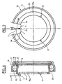
- FIGS. 8 and 9 The embodiment illustrated in FIGS. 8 and 9 is similar to that of Figures 6 and 7 except that the protrusions 127 are obtained by puncturing the sheet metal leading to the formation of inclined legs 27, the radial edge of which protrudes and is adapted to engage with one of the sides 4a of a finger 4 while being parallel to said flank 4a.
- the material is pushed outward without removal of chips and the protrusions 27, 127 are parallel to the sides 4a.
- the declutching device comprises a diaphragm 1 identical to that of FIGS. 1 and 2 and a stop 11 slightly different from that of FIGS. 3 to 5, in that it comprises a thrust bearing 13 provided with an outer rotating ring 16, and an inner non-rotating ring 17, between which is disposed a row of balls 18.
- the rotating ring 16 supports, on the side of the operating element 14, a seal 20.
- the rotating ring 16 comprises a radial portion 25 rounded and in contact with the fingers 4 of the diaphragm 1.
- Several depressions 26 are provided by pushing back the material forming the radial portion 25.
- a finger 4 can be housed in each depression 26.
- a member self-aligning elastic 30 allowing the radial displacement of the bearing 13 with respect to the operating element 14 and its self-centering with respect to the diaphragm.
- the elastic organ self-aligning 30 projects axially beyond the end of the non-rotating ring 17, in the direction of the rotating ring 16 to form a labyrinth seal 31.
- the present invention is not not limited to the embodiments described.
- the protrusions 27, 127 can be of different axial height so that the diaphragm fingers axially salient do not necessarily cooperate with protuberances.
- a clutch device is obtained economical with rolling bearing and diaphragm lasting prolonged life due to the rotational connection of the diaphragm with the rotating ring and which places less stress on the clutch housing, while suitable for any type of diaphragm including internally, the declutching device according to the invention can operate with a diaphragm with reduced width slots.
- the diaphragm is always in the same position when the clutch is engaged and that in no case can the width of the slits be reduced so that the ends of the diaphragm fingers can pinch the deformations when these consist of a material repulsion outwards.
Description
La présente invention concerne le domaine des dispositifs débrayeurs pour embrayages à friction du type poussé, notamment pour véhicules automobiles.The present invention relates to the field of devices declutchers for friction clutches of the thrust type, in particular for motor vehicles.
De tels dispositifs comportent une butée de débrayage en appui sur l'extrémité interne d'un diaphragme troué centralement.Such devices include a clutch release bearing in support on the internal end of a centrally perforated diaphragm.
La butée de débrayage comporte un palier à roulement de butée usuellement à bagues concentriques et coaxiales, avec une bague tournante, profilée pour un contact local avec le diaphragme pourvu d'une partie périphérique externe en forme de rondelle Belleville prolongée radialement vers l'intérieur par une partie centrale fragmentée en doigts radiaux séparés deux à deux par des fentes borgnes, dont le fond ou extrémité externe est constitué par des orifices élargis implantés à la périphérie interne de la rondelle Belleville du diaphragme de forme tronconique à l'état libre. Les fentes débouchent intérieurement dans le trou central du diaphragme. La bague tournante agit sur l'extrémité interne des doigts du diaphragme et présente une partie bombée, lorsque les doigts du diaphragme sont plans et une forme annulaire plane lorsque les doigts du diaphragme sont bombés à leur extrémité interne.The clutch release bearing has a rolling bearing of stop usually with concentric and coaxial rings, with a ring rotating, profiled for local contact with the diaphragm provided an outer peripheral part in the shape of a Belleville washer extended radially inwards by a central part fragmented into radial fingers separated in pairs by slits blind, the bottom or outer end of which is constituted by enlarged holes located on the inner periphery of the washer Belleville of the tapered diaphragm in the free state. The slots open internally into the central hole of the diaphragm. The rotating ring acts on the inner end of the fingers of the diaphragm and has a domed part, when the fingers of the diaphragm are planar and a planar annular shape when the fingers diaphragm are domed at their inner end.
La bague non tournante est, pour la manoeuvre du palier à roulement, attelée axialement à un élément de manoeuvre présentant un manchon central monté sur un tube-guide en vue du déplacement axial de l'élément de manoeuvre par rapport au tube-guide traversé par un arbre mené, tandis que le diaphragme est solidaire en rotation d'un arbre menant. L'élément de manoeuvre porte ainsi la butée de débrayage.The non-rotating ring is, for operating the bearing at bearing, axially coupled to an operating element having a central sleeve mounted on a guide tube for movement axial of the operating element with respect to the guide tube through which a driven shaft, while the diaphragm is integral in rotation with a leading tree. The operating element thus carries the stop of walkout.
La bague non tournante du palier à roulement peut être fixe radialement par rapport à l'élément de manoeuvre en étant, par exemple emmanchée à force sur l'extrémité avant du manchon de l'élément de manoeuvre. En variante, le palier à roulement peut se déplacer radialement par rapport à l'élément de manoeuvre, la butée étant alors appelée butée de débrayage autocentreuse. Les moyens d'attelage de la bague non tournante à l'élément de manoeuvre comportent alors, par exemple, des moyens élastiques à action axiale tels qu'une rondelle élastique du type rondelle Belleville ou du type rondelle ondulée. En variante il peut s'agir de crochets ou d'une rondelle déformable radialement à la manière d'un circlips.The non-rotating ring of the rolling bearing can be fixed radially with respect to the operating element being, by example press fit on the front end of the sleeve the operating element. Alternatively, the rolling bearing can be move radially with respect to the operating element, the stop being then called self-centering declutching stop. Ways coupling of the non-rotating ring to the operating element then comprise, for example, elastic means with axial action such as an elastic washer of the Belleville washer type or of the type wavy washer. Alternatively it may be hooks or a radially deformable washer like a circlip.
Les moyens élastiques prennent appui directement sur l'élément de manoeuvre ou sur un capot solidaire par sertissage ou encliquetage dudit élément de manoeuvre pour agir sur la bague non tournante et solliciter celle-ci en contact avec un épaulement solidaire de l'élément de manoeuvre.The elastic means bear directly on the operating element or on a cover secured by crimping or latching of said operating element to act on the ring not rotating and apply it in contact with an integral shoulder of the operating element.
On peut également prévoir un dispositif d'autocentrage par un manchon en matière élastique à action radiale interposé radialement entre la bague non tournante et l'élément de manoeuvre.One can also provide a self-centering device by a sleeve of elastic material with radial action interposed radially between the non-rotating ring and the operating element.
L'élément de manoeuvre est conformé pour être soumis à l'action de moyens de commande en déplacement du type mécanique, hydraulique ou électromécanique. Ces moyens de commande permettent de déplacer axialement la butée de débrayage par rapport au tube-guide.The operating element is shaped to be subjected to the action of mechanical type displacement control means, hydraulic or electromechanical. These control means allow the clutch release bearing to be moved axially with respect to to the guide tube.
Par exemple, le tube-guide est fixé directement sur une partie fixe telle que le carter de la boíte de vitesses et le manchon de l'élément de manoeuvre porte au niveau de son extrémité arrière un flasque transversal, revêtu éventuellement d'une plaque d'appui, sur lequel agissent les doigts d'une fourchette de débrayage actionnée par la pédale de débrayage avec intervention d'un ressort, dit de précharge, dans la chaíne cinématique allant de la pédale à la fourchette. Ce ressort de précharge permet de maintenir la butée de débrayage en appui constant sur le diaphragme pour réduire l'usure et augmenter la durée de vie du roulement. En manoeuvrant la fourchette, on déplace axialement l'élément de manoeuvre le long du tube-guide de sorte que la butée de débrayage agit en poussant sur l'extrémité interne des doigts du diaphragme, celui-ci ramenant la butée à sa position initiale dès que l'on cesse d'agir sur la pédale de débrayage. En variante, le manchon de l'élément de manoeuvre peut consister en un piston d'une commande hydraulique comprenant une partie fixe, par exemple fixée sur le carter de la boíte de vitesse et définissant une cavité borgne à l'intérieur de laquelle se déplace de manière étanche le piston.For example, the guide tube is fixed directly on a part fixed such as the gearbox housing and the sleeve the operating element carries at its rear end a transverse flange, possibly coated with a support plate, on which act the fingers of a clutch release fork actuated by the clutch pedal with the intervention of a spring, called preload, in the kinematic chain going from the pedal to the fork. This preload spring keeps the stopper declutching with constant pressure on the diaphragm to reduce wear and increase the service life of the bearing. By manipulating the fork, the operating element is moved axially along the guide tube so that the clutch release bearing acts by pushing on the end internal of the diaphragm fingers, the latter bringing the stopper to its initial position as soon as you stop acting on the clutch pedal. Alternatively, the sleeve of the operating element may consist of a piston of a hydraulic control comprising a fixed part, by example fixed on the gearbox housing and defining a blind cavity inside which the seal moves piston.
En variante, le tube-guide est fileté et coopère avec le manchon de l'élément de manoeuvre formant écrou en étant monté sur le tube-guide formant vis. Ce tube est mobile en rotation et est fixe axialement, tandis que le manchon est fixe en rotation, par exemple à l'aide de languettes élastiques reliant le manchon à un boítier fixe, et est mobile en translation. Le tube-guide est alors porté par le boítier fixe par l'intermédiaire d'un roulement. A l'aide d'un câble, on déplace en rotation le tube-guide et en translation le manchon. Le tube-guide peut également être entraíné en rotation par un moteur électrique solidaire d'une partie fixe.Alternatively, the guide tube is threaded and cooperates with the sleeve of the operating element forming a nut while being mounted on the guide tube forming a screw. This tube is movable in rotation and is fixed axially, while the sleeve is fixed in rotation, for example at using elastic tabs connecting the sleeve to a fixed housing, and is mobile in translation. The guide tube is then carried by the housing fixed by means of a bearing. Using a cable, we move in rotation the guide tube and in translation the sleeve. The guide tube can also be rotated by an electric motor secured to a fixed part.
Lors de sa fabrication, le diaphragme subit des opérations mécaniques de découpe et de mise en forme conique ainsi que des opérations de traitement thermique, notamment de trempe, afin de lui conférer la forme voulue ainsi que la dureté et l'élasticité recherchées. Il en résulte certains défauts géométriques, et en pratique les extrémités des doigts du diaphragme ne sont pas toutes dans le même plan.During its manufacture, the diaphragm undergoes operations mechanical cutting and conical shaping as well as heat treatment operations, in particular quenching, in order to give the desired shape as well as the desired hardness and elasticity. This results in certain geometric defects, and in practice the the tips of the diaphragm fingers are not all in the same plan.
Le document FR-A-2 234 485 (RANSOME HOFFMANN POLLARD) concerne un embrayage classique dans lequel le diaphragme est monté sous contrainte et prend appui sur un appui primaire porté par le fond troué centralement d'un couvercle de forme creuse fixé, par exemple par des vis, à un volant d'entraínement solidaire en rotation d'un arbre menant. L'appui primaire est de forme annulaire et est réalisé par emboutissage du fond du couvercle ou en variante consiste en un jonc porté par des colonnettes fixées par rivetage au fond du couvercle et traversant chacune un orifice élargi du diaphragme pour porter un jonc, formant appui secondaire, disposé en regard de l'appui primaire en étant interposé entre les têtes des colonnettes et le diaphragme du côté de celui-ci, tourné à l'opposé du fond du couvercle.Document FR-A-2 234 485 (RANSOME HOFFMANN POLLARD) relates to a conventional clutch in which the diaphragm is mounted under stress and is supported on a primary support carried by the centrally perforated bottom of a fixed hollow cover, by example by screws, to a steering wheel integral in rotation of a leading tree. The primary support is annular in shape and is produced by stamping the bottom of the cover or alternatively consists in a ring carried by columns fixed by riveting to the bottom of the cover and each passing through an enlarged orifice of the diaphragm for wear a ring, forming a secondary support, placed opposite the support primary by being interposed between the heads of the balusters and the diaphragm on the side thereof, turned away from the bottom of the lid.
En variante, les colonnettes sont remplacées par des pattes issues par découpe et pliage du fond du couvercle. Les pattes traversent des orifices élargis du diaphragme et sont repliées à leur extrémité libre radialement vers l'extérieur pour former un coude de calage pour une couronne-jonc présentant une partie arrondie pour contact avec la face du diaphragme tournée à l'opposé du fond du couvercle et former ainsi l'appui secondaire. La périphérie interne de la rondelle Belleville est montée de manière basculante entre les appuis primaire et secondaire implantés en vis-à-vis. La périphérie externe de la rondelle Belleville s'appuie sur un bossage fragmenté que présente la face dorsale d'un plateau de pression lié en rotation au couvercle tout en étant mobile axialement par rapport au couvercle, généralement grâce à des languettes élastiques d'orientation tangentielle.Alternatively, the balusters are replaced by legs issues by cutting and folding the bottom of the cover. The paws pass through enlarged apertures in the diaphragm and are folded back at their free end radially outward to form a bend of setting for a crown ring with a rounded part for contact with the face of the diaphragm turned away from the bottom of the cover and thus form the secondary support. The inner periphery of the Belleville washer is pivotally mounted between the primary and secondary supports located opposite. The suburbs of the Belleville washer is based on a fragmented boss that presents the dorsal face of a pressure plate linked in rotation to the cover while being axially movable relative to the cover, usually with elastic orientation tabs tangential.
Des garnitures de friction d'un disque de friction sont interposées axialement entre le volant d'entraínement et la face frontale du plateau de pression. A sa périphérie interne le disque de friction présente un moyeu pour son calage en rotation sur un arbre mené. Dans le cadre d'une application pour véhicule automobile, l'arbre mené est l'arbre d'entrée de la boíte de vitesses, et l'arbre menant est le vilebrequin du moteur du véhicule sur lequel se fixe le volant d'entraínement.Friction linings of a friction disc are axially interposed between the drive wheel and the face front of the pressure plate. At its internal periphery the disc of friction presents a hub for its rotation setting on a shaft conducted. As part of a motor vehicle application, the driven shaft is the input shaft of the gearbox, and the shaft leading is the crankshaft of the vehicle engine on which the driving wheel.
Lorsque l'embrayage est engagé, le diaphragme prend appui sur l'appui primaire et sur le bossage du plateau de pression pour solliciter celui-ci en direction du volant et serrer les garnitures de friction. Le couple est ainsi transmis de l'arbre menant à l'arbre mené. Pour désengager l'embrayage et interrompre la transmission de couple, on désactive les moyens . de commande en déplaçant l'élément de manoeuvre de sorte que la bague tournante pousse sur le diaphragme. Ce dernier prend alors appui sur son appui secondaire et bascule de sorte que la charge qu'il exerce sur le plateau de pression diminue progressivement puis s'annule. Les languettes élastiques rappellent le plateau de pression en direction du fond du couvercle pour libérer les garnitures de friction. Les colonnettes ou les pattes sont donc sollicitées à chaque opération de débrayage.When the clutch is engaged, the diaphragm is supported on the primary support and on the boss of the pressure plate to push it towards the steering wheel and tighten the trim friction. The torque is thus transmitted from the shaft leading to the driven shaft. To disengage the clutch and interrupt the torque transmission, we deactivate the means. by moving the element from maneuver so that the rotating ring pushes on the diaphragm. The latter then takes support on its secondary support and switches from so that the load it exerts on the pressure plate decreases gradually then vanishes. The elastic tabs recall the pressure plate towards the bottom of the cover to release the friction linings. The balusters or the legs are therefore requested at each clutch release operation.
Dans certains cas, on a constaté, malgré le ressort de rappel, la présence d'une rotation relative entre le diaphragme, et la butée de débrayage entraínant des phénomènes d'usure, notamment au niveau des doigts du diaphragme de dureté inférieure à celle de la bague tournante.In some cases, despite the return spring, the presence of a relative rotation between the diaphragm, and the stop of declutching causing wear phenomena, especially at the level diaphragm fingers of lower hardness than that of the ring rotating.
Le document FR-A-2 234 485 propose de réaliser un entraínement positif entre la bague tournante de la butée de débrayage, portée par le couvercle de l'embrayage, et le diaphragme. La bague tournante est montée sur ou dans un manchon fixé sur le couvercle à l'aide des colonnettes et présente deux saillies diamétralement opposées, qui pénètrent chacune dans une fente du diaphragme. Il en résulte certains inconvénients car la butée de débrayage n'est plus de type standard, le couvercle de l'embrayage subit des contraintes supplémentaires et des problèmes d'équilibrage dynamique de l'embrayage apparaissent du fait que le couvercle porte la butée de débrayage. La bague tournante du roulement doit être relativement massive du fait qu'elle est montée solidaire d'un manchon porteur et subit des contraintes supplémentaires, notamment lorsqu'elle coulisse axialement par rapport au manchon. On peut difficilement utiliser dans ce type de dispositif une bague intérieure tournante en contact direct avec le diaphragme sauf à retrouver les inconvénients mentionnés plus haut et à donner à ladite bague, et donc à la butée, un encombrement axial important. Enfin, les saillies ont une largeur non négligeable qui conditionne la largeur des fentes du diaphragme.Document FR-A-2 234 485 proposes to carry out a positive drive between the rotating ring of the clutch release bearing, carried by the clutch cover, and the diaphragm. The ring rotating is mounted on or in a sleeve fixed on the cover to using the balusters and has two diametrically protruding opposite, which each enter a slit in the diaphragm. It certain drawbacks result because the release bearing is no longer standard type, the clutch cover is stressed additional and dynamic balancing issues of the clutch appear because the cover carries the stopper walkout. The rotating ring of the bearing must be relatively massive because it is mounted integral with a support sleeve and undergoes additional stresses, especially when it slides axially with respect to the sleeve. It is difficult to use in this type of device a rotating inner ring in direct contact with the diaphragm except to find the disadvantages mentioned more top and to give said ring, and therefore to the stopper, a space requirement important axial. Finally, the projections have a significant width which conditions the width of the diaphragm slots.
La présente invention a pour objet de remédier à ces différents inconvénients et de proposer un dispositif de débrayage simple et économique.The object of the present invention is to remedy these different disadvantages and to propose a declutching device simple and economical.
La présente invention a pour objet, notamment de proposer un dispositif de débrayage dans lequel la bague tournante, de faible épaisseur, est en contact direct et permanent en toute circonstance avec le diaphragme, celui-ci étant pourvu de fentes dont la largeur est indépendante de la butée.The object of the present invention is, in particular to propose a declutching device in which the rotating ring, weak thickness, is in direct and permanent contact in all circumstances with the diaphragm, the latter being provided with slots the width of which is independent of the stop.
Le dispositif de débrayage, selon l'invention, comprend un diaphragme pourvu d'un trou central et découpé en doigts orientés radialement vers l'intérieur, un palier à roulement de butée et un élément de manoeuvre monté sur une partie distincte de celle supportant le diaphragme et en contact au moins axial avec le palier à roulement. Le palier à roulement comprend une bague tournante dont une portion radiale est en appui sur l'extrémité interne des doigts du diaphragme, une bague non tournante dont une portion radiale est en contact avec l'élément de manoeuvre, et une rangée d'éléments roulants. La bague tournante est réalisée en tôle emboutie et comprend sur sa portion radiale en contact avec le diaphragme, au moins une déformation axiale obtenue sans enlèvement de matière, et dont les bords sont capables de coopérer avec les flancs d'un doigt du diaphragme, la déformation étant de dimension inférieure à l'épaisseur d'un doigt du diaphragme.The declutching device according to the invention comprises a diaphragm provided with a central hole and cut into oriented fingers radially inwards, a thrust bearing and a operating element mounted on a separate part from that supporting the diaphragm and in at least axial contact with the bearing to rolling. The rolling bearing includes a rotating ring, a radial portion is supported on the inner end of the fingers of the diaphragm, a non-rotating ring of which a radial portion is in contact with the operating element, and a row of elements rolling. The rotating ring is made of pressed sheet metal and includes on its radial portion in contact with the diaphragm, at least one axial deformation obtained without removal of material, and the edges are able to cooperate with the sides of a finger of the diaphragm, the deformation being of dimension smaller than the thickness of a diaphragm finger.
La déformation axiale pourra être obtenue par exemple au moyen d'une presse.The axial deformation can be obtained for example at by means of a press.
Grâce à l'invention, on obtient un dispositif de débrayage qui ménage le couvercle de l'embrayage, et on peut utiliser une butée de débrayage de type standard du fait que l'élément de manoeuvre n'est pas porté par la même partie que le diaphragme. Seule la bague tournante du palier à roulement est modifiée, et ce de manière économique car, d'une part, la bague tournante est de faible épaisseur et, d'autre part, les déformations sont de faibles dimensions axiales. Les déformations sont réalisées sans enlèvement de copeaux, ce qui peut être réalisé aisément et de façon économique durant le processus d'emboutissage à la presse de la bague. L'invention tire parti des défauts géométriques des doigts du diaphragme qui permettent d'utiliser des déformations de faibles dimensions. La déformation viendra en prise avec le flanc de l'un des doigts du diaphragme le plus décalé axialement par rapport aux autres.Thanks to the invention, a clutch device is obtained which clean the clutch cover, and you can use a stopper standard type clutch because the operating element is not not carried by the same part as the diaphragm. Only the ring of the rolling bearing is changed so that economical because, on the one hand, the rotating ring is thin and, on the other hand, the deformations are of small axial dimensions. The deformations are carried out without removal of chips, which can be carried out easily and economically during the process stamping the ring. The invention takes advantage of geometric defects of the diaphragm fingers which allow to use deformations of small dimensions. The deformation will engage the flank of one of the most diaphragm fingers axially offset from the others.
En outre, le nombre de déformations nécessaires est très faible du fait qu'une fois la liaison positive en rotation établie entre le diaphragme et la bague tournante de la butée, cette liaison aura tendance à se renforcer avec la durée de fonctionnement de la butée.In addition, the number of deformations required is very weak due to the fact that once the positive rotating link is established between the diaphragm and the rotating ring of the stop, this connection will have tendency to strengthen with the duration of operation of the stop.
En effet, à chaque manoeuvre de l'embrayage, il se produit un léger glissement radial relatif entre les doigts du diaphragme et la bague tournante de la butée. La légère usure qui en résulte produira à la longue une légère incrustation des doigts du diaphragme sur la bague de la butée, renforçant ainsi la liaison en rotation entre ces pièces.Indeed, with each operation of the clutch, there is a slight relative radial slip between the diaphragm fingers and the rotating ring of the stop. The resulting light wear will produce along a slight inlay of the diaphragm fingers on the stop ring, thereby strengthening the rotational connection between these rooms.
Ce phénomène d'incrustation est rendu possible du fait que les doigts du diaphragme ont une dureté non négligeable, bien qu'inférieure à celle de la bague tournante qui a une faible épaisseur.This incrustation phenomenon is made possible by the fact that the diaphragm fingers have a significant hardness, well than lower than that of the rotating ring which has a small thickness.
De même, une bague tournante en tôle emboutie présente une certaine aptitude à des microdéformations locales sous l'action des doigts du diaphragme lors des manoeuvres de débrayage ce qui favorise également le phénomène d'incrustation.Similarly, a rotating ring in pressed sheet metal has a certain aptitude for local micro-deformations under the action of diaphragm fingers during disengagement operations which also promotes the phenomenon of incrustation.
Par exemple, la déformation peut consister en un repoussage de matière vers l'intérieur, en direction des éléments roulants du palier à roulement. Ce repoussage de matière conduit à la formation d'une dépression en forme de rainure radiale avec des bords latéraux parallèles aux flancs latéraux d'un doigt du diaphragme, la largeur de la rainure étant légèrement supérieure à celle d'un doigt du diaphragme.For example, the deformation can consist of a pushing back material inward, toward the rolling elements of the rolling bearing. This material repel leads to the formation a depression in the form of a radial groove with lateral edges parallel to the lateral flanks of a diaphragm finger, the width of the groove being slightly greater than that of a finger of the diaphragm.
Au montage, on amène en contact la butée sur le diaphragme dans n'importe quelle position circonférentielle, et toute rotation relative du diaphragme par rapport à la butée conduit à ce que l'un des doigts, qui fait partie de ceux les plus décalés axialement par rapport aux autres, vient en prise dans la dépression en entraínant une liaison positive en rotation entre le diaphragme et la butée de débrayage.During assembly, the stop is brought into contact with the diaphragm in any circumferential position, and any rotation relative of the diaphragm with respect to the stop leads to one of the fingers, which is one of the most axially offset to others, engages in depression causing a bond positive in rotation between the diaphragm and the clutch release bearing.
En variante, le repoussage de matière peut s'effectuer vers l'extérieur, en direction opposée aux éléments roulants dudit palier et conduire à la formation d'une protubérance axiale propre à venir en prise avec un bord de l'un des doigts les plus décalés axialement pour liaison positive en rotation entre le diaphragme et la butée. Cette protubérance pourra, par exemple, former un picot radialement de forme oblongue et de largeur inférieure à celle d'une fente formant un espace circonférentiel séparant deux doigts adjacents du diaphragme. As a variant, the material can be pushed back towards outside, in the direction opposite to the rolling elements of said bearing and lead to the formation of a proper axial protuberance to come in taken with an edge of one of the most axially offset fingers to positive connection in rotation between the diaphragm and the stop. This protrusion may, for example, form a spike radially oblong shape and less width than a slit forming a circumferential space between two adjacent fingers of the diaphragm.
La protubérance peut également être obtenue par un crevé de la tôle conduisant à la formation d'une patte inclinée dont l'arête radiale est en saillie.The protuberance can also be obtained by a puncture of the sheet metal leading to the formation of an inclined leg whose edge radial is projecting.
Le diaphragme peut présenter des fentes de largeur constante en-deçà des orifices élargis, ou des fentes de largeur réduite à son extrémité interne pour augmenter la surface de contact du diaphragme et de la bague tournante.The diaphragm may have slots of constant width below the widened orifices, or slits of width reduced to its inner end to increase the contact area of the diaphragm and the rotating ring.
L'invention est donc d'un emploi universel du fait que la déformation est réalisée sans enlèvement de matière et à partir d'une bague emboutie de faible épaisseur. En effet, même dans le cas où la déformation de matière s'effectue vers l'extérieur, on peut aisément contrôler celle-ci pour qu'elle soit inférieure à la largeur d'une fente de largeur réduite. C'est pour cette raison que la déformation se présente, dans ce cas, sous la forme d'un picot ou d'un crevé.The invention is therefore of universal use since the deformation is carried out without removal of material and from a stamped ring of small thickness. Indeed, even in the case where the material deformation takes place outwards, it is easy to control it to be less than the width of a slit of reduced width. It is for this reason that the deformation is present, in this case, in the form of a picot or a puncture.
Ainsi qu'on l'aura compris, le repoussage de matière est réalisé avant les opérations de traitement thermique de la bague tournante destinées à lui conférer la dureté recherchée.As we will have understood, the material repulsion is performed before the ring heat treatment operations rotating intended to give it the desired hardness.
Dans un mode de réalisation de l'invention, on prévoit que la déformation est de hauteur axiale inférieure à la moitié de l'épaisseur d'un doigt du diaphragme.In one embodiment of the invention, it is provided that the deformation is of axial height less than half the thickness of a diaphragm finger.
Avantageusement, deux déformations diamétralement opposées sont prévues. On peut aussi prévoir trois déformations régulièrement réparties circonférentiellement. D'une manière générale, le nombre des déformations est largement inférieur au nombre de fentes du diaphragme.Advantageously, two diametrically deformations opposite are planned. We can also predict three deformations regularly distributed circumferentially. In a general way, the number of deformations is much lower than the number of diaphragm slots.
Le dispositif suivant l'invention pourra avantageusement être utilisé en combinaison avec un système de rattrapage d'usure de l'embrayage qui garantira le maintien d'une plage dimensionnelle stable des fentes séparant circonférentiellement les doigts du diaphragme quelle que soit l'usure de l'embrayage.The device according to the invention could advantageously be used in combination with a wear take-up system the clutch which will guarantee the maintenance of a dimensional range stable slots circumferentially separating the fingers from the diaphragm regardless of clutch wear.
L'élément de manoeuvre peut présenter un manchon central pour coulissement axial le long d'un tube guide solidaire d'une partie fixe, par exemple le carter de la boíte de vitesses distinct du bloc moteur portant le diaphragme. En variante, le manchon peut former un écrou entraíné en translation par le tube-guide formant vis lui-même monté rotatif.The operating element may have a central sleeve for axial sliding along a guide tube integral with a part fixed, for example the gearbox housing separate from the block motor carrying the diaphragm. Alternatively, the sleeve may form a nut driven in translation by the guide tube forming the screw itself rotatably mounted.
L'élément de manoeuvre peut être actionné mécaniquement par exemple par un câble ou une fourchette, hydrauliquement en formant dans ce cas un piston ou de manière électromécanique.The operating element can be mechanically actuated for example by a cable or a fork, hydraulically in in this case forming a piston or electromechanically.
Ces différentes variantes sont possibles car l'élément de manoeuvre est conformé pour être monté sur une partie distincte de celle portant le diaphragme. Bien entendu, la bague tournante peut être la bague intérieure ou extérieure du roulement de butée.These different variants are possible because the element of maneuver is shaped to be mounted on a separate part of the one with the diaphragm. Of course, the rotating ring can be the inner or outer ring of the thrust bearing.
L'invention sera mieux comprise à l'étude de la description
détaillée de modes de réalisation pris à titre d'exemples nullement
limitatifs et illustrés par les dessins annexés, sur lesquels :
Comme on peut le voir sur les figures 1 et 2, le diaphragme 1
comprend une partie périphérique externe 2 en forme de rondelle
Belleville tronconique à l'état libre, et une partie centrale 3 située
dans le prolongement radial vers l'intérieur de la partie externe 2, et
qui est circulairement fragmentée (découpée) en doigts radiaux 4 par
des saignées formant des fentes 5. Chaque fente 5 s'étend d'une
extrémité externe borgne 6 élargie implantée à la périphérie interne de
la partie périphérique 2, à une extrémité interne ouverte 7, qui est de
largeur circonférentielle réduite, et débouche dans un trou central 8
commun à toutes les fentes 5.As can be seen in Figures 1 and 2, the diaphragm 1
includes an external
La largeur réduite des fentes 5 au niveau de leur extrémité
ouverte 7 est obtenue, par exemple par des opérations de tranchage.
On peut réaliser en deux opérations distinctes les deux bords radiaux 9
et 10 d'une telle fente 5, à savoir, une première opération de tranchage
au cours de laquelle on réalise d'abord l'un des bords 9, 10 en
question, puis une deuxième opération de tranchage au cours de
laquelle on réalise l'autre desdits bords appelés par la suite flancs 4a.The reduced width of the
Pour des raisons de clarté des dessins, les doigts 4 du
diaphragme 1 tels que représentés sur la figure 2 sont tous situés sur
une même surface de révolution tronconique. Toutefois, un
diaphragme 1 réel aura des doigts 4 plus ou moins décalés axialement
dans une direction ou une autre compte tenu du mode de fabrication
précité du diaphragme.For reasons of clarity of the drawings, the
Tel qu'illustré sur les figures 3 à 5, le dispositif de débrayage
comprend un diaphragme 1, une butée d'embrayage 11 et un tube-guide
12 partiellement représenté. La butée 11 est montée coulissant
axialement sur un tube-guide 12 monté sur le carter de boíte de
vitesses, non représenté, et donc sur une partie distincte de celle
portant le diaphragme. La butée 11 comprend un palier à roulement de
butée 13, un élément de manoeuvre 14 soumis à l'action d'un organe de
commande 15, ici une fourchette de débrayage. Le roulement de butée
13 comprend une bague intérieure tournante 16, réalisée en tôle mince,
et une bague extérieure non tournante 17 également réalisée en tôle
mince, entre lesquelles est disposée une rangée d'éléments roulants,
par exemple des billes 18 maintenue par une cage 19. Un joint
d'étanchéité 20 est emmanché sur un alésage de la bague extérieure 17
du côté du diaphragme 1. La bague extérieure 17 comprend du côté
opposé au diaphragme 1, une portion radiale 21.As illustrated in Figures 3 to 5, the declutching device
includes a diaphragm 1, a
L'élément de manoeuvre 14 comprend une portion cylindrique
22 et une collerette radiale 23 dirigée vers l'intérieur contre laquelle
viennent porter, d'un côté la portion radiale 21 de la bague extérieure
17, et de l'autre côté l'organe de commande 15 par l'intermédiaire des
doigts de la fourchette de débrayage. La bague extérieure 17 du
roulement de butée 13 est maintenue en contact avec ladite collerette
radiale 23 par une rondelle biconique 24 dont le bord externe porte sur
la portion radiale 21 de la bague externe 17 et dont le bord interne,
découpé en languettes, est logé dans une rainure 22a de la portion
cylindrique 22 de l'élément de manoeuvre 14, pour assurer ainsi
l'appui axial du roulement de butée 13 contre l'élément de manoeuvre
14.The operating
Grâce à un jeu radial contre les bagues 16, 17 du roulement
de butée et la portion 22 de l'élément de manoeuvre 14, le roulement
de butée peut se déplacer radialement de façon contrôlée par rapport à
l'élément de manoeuvre 14 et venir ainsi s'autocentrer en
fonctionnement par rapport au diaphragme.Thanks to a radial clearance against the
La bague intérieure tournante 16 du roulement de butée 13
comprend, à son extrémité dirigée vers le diaphragme 1, une portion
radiale 25 pourvue sur son bord extérieur d'une surface arrondie
convexe 25a en contact avec l'extrémité des doigts 4 du diaphragme 1.
Sur la surface convexe 25a de la portion radiale 25, on effectue deux
déformations diamétralement opposées formant des dépressions 26 en
forme de rainures radiales. La déformation est effectuée par
repoussage de la matière vers l'intérieur formant la portion radiale 25
sur une faible épaisseur. La profondeur de la dépression 26 est
largement inférieure à la moitié de l'épaisseur d'un doigt 4 du
diaphragme 1. Dès qu'une rotation se produit entre la butée 11 et le
diaphragme 1, un doigt 4 de ce dernier vient se loger dans la
dépression 26 et empêche toute rotation relative ultérieure de la butée
11 et du diaphragme 1.The inner
Comme on le voit plus particulièrement sur la figure 5, les
flancs 4a des doigts 4 peuvent entrer en contact avec les bords 26a des
dépressions 26. En pratique, en raison des tolérances de fabrication, il
se peut que seul un des bords 26a entre en contact avec un flanc 4a
d'un doigt 4. Dans tous les cas, le diaphragme 1 et la bague tournante
16 sont solidaires en rotation.As can be seen more particularly in FIG. 5, the
Le mode de réalisation illustré sur les figures 6 et 7 est
semblable à celui des figures précédentes à ceci près que, au lieu des
creux, la bague intérieure tournante 16 comprend trois protubérances
27 en saillie et en forme de picots entre deux doigts 4 adjacents du
diaphragme 1. Les protubérances 27 sont radialement de forme
oblongues et de très faibles dimensions circonférentielles de façon à
venir se loger dans l'une quelconque des fentes 5 séparant les doigts 4
du diaphragme 1. Les protubérances 27 sont d'épaisseur inférieure à
celle des doigts 4 du diaphragme 1 en étant radialement de forme
oblongue pour un bon contact avec lesdits doigts.The embodiment illustrated in FIGS. 6 and 7 is
similar to that of the previous figures except that, instead of
hollow, the rotating
Le mode de réalisation illustré sur les figures 8 et 9 est
semblable à celui des figures 6 et 7 à ceci près que les protubérances
127 sont obtenues au moyen de crevés de la tôle conduisant à la
formation de pattes inclinées 27 dont l'arête radiale est en saillie et est
adaptée à venir en prise avec l'un des flancs 4a d'un doigt 4 en étant
parallèle audit flanc 4a. Ainsi qu'on l'aura compris, dans les figures 6
à 9, on repousse la matière vers l'extérieur sans enlèvement de
copeaux et les protubérances 27, 127 sont parallèles aux flancs 4a.The embodiment illustrated in FIGS. 8 and 9 is
similar to that of Figures 6 and 7 except that the
Dans les figures 3 à 5 on repousse la matière vers l'intérieur
sans enlèvement de copeaux, et les bords 26a des dépressions sont
parallèles aux flancs 4a.In Figures 3 to 5 we push the material inward
without chip removal, and the
Bien entendu, on put inverser les structures, ainsi sur la
figure 10, le dispositif de débrayage comprend un diaphragme 1
identique à celui des figures 1 et 2 et une butée 11 légèrement
différente de celle des figures 3 à 5, en ce sens qu'elle comprend un
roulement de butée 13 pourvu d'une bague tournante 16 extérieure, et
d'une bague non tournante 17 intérieure , entre lesquelles est disposée
une rangée de billes 18. La bague tournante 16 supporte, du côté de
l'élément de manoeuvre 14, un joint d'étanchéité 20. A son extrémité
opposée, la bague tournante 16 comprend une portion radiale 25
arrondie et en contact avec les doigts 4 du diaphragme 1. Plusieurs
dépressions 26 sont prévues par repoussage de la matière formant la
portion radiale 25. Un doigt 4 peut venir se loger dans chaque
dépression 26. Of course, we could reverse the structures, so on the
Figure 10, the declutching device comprises a diaphragm 1
identical to that of FIGS. 1 and 2 and a
L'élément de manoeuvre 14, réalisé en matériau synthétique,
est pourvu sur sa collerette radiale 23 dirigée vers l'extérieur, d'une
plaque métallique de renforcement 29 en contact avec l'organe de
commande 15 qui se présente également sous forme d'une fourchette
de débrayage. Entre la portion tubulaire 22 de l'élément de manoeuvre
14 et la bague non tournante 17, est disposé radialement un organe
élastique d'autoalignement 30 autorisant le déplacement radial du
roulement 13 par rapport à l'élément de manoeuvre 14 et son
autocentrage par rapport au diaphragme. L'organe élastique
d'autoalignement 30 fait saillie axialement au-delà de l'extrémité de la
bague non tournante 17, en direction de la bague tournante 16 pour
former un joint labyrinthe 31. Bien entendu, la présente invention n'est
pas limitée aux exemples de réalisation décrits.The operating
En particulier, les protubérances 27, 127 peuvent être de
hauteur axiale différente de sorte que les doigts du diaphragme les
plus saillants axialement ne coopèrent pas forcément avec les
protubérances.In particular, the
D'autre part, dans un mode de réalisation du type de celui des figures 3 à 5, on peut prévoir trois dépressions réparties à 120° les unes par rapport aux autres.On the other hand, in an embodiment of the type of that of Figures 3 to 5, we can provide three depressions distributed at 120 ° the relative to each other.
Grâce à l'invention, on obtient un dispositif de débrayage économique dont le palier à roulement et le diaphragme ont une durée de vie prolongée du fait de la liaison en rotation du diaphragme avec la bague tournante et qui sollicite moins le carter d'embrayage, tout en convenant à n'importe quel type de diaphragme notamment intérieurement, le dispositif débrayeur suivant l'invention pouvant fonctionner avec un diaphragme à fentes de largeur réduite.Thanks to the invention, a clutch device is obtained economical with rolling bearing and diaphragm lasting prolonged life due to the rotational connection of the diaphragm with the rotating ring and which places less stress on the clutch housing, while suitable for any type of diaphragm including internally, the declutching device according to the invention can operate with a diaphragm with reduced width slots.
Ainsi qu'on l'aura compris, en dotant l'embrayage d'un dispositif compensant l'usure de ses garnitures de friction appelé dispositif à rattrapage d'usure, on garantit que le diaphragme est toujours dans la même position à l'état d'embrayage engagé et qu'en aucun cas, la largeur des fentes ne puisse diminuer de façon telle que les extrémités des doigts du diaphragme puissent venir pincer les déformations lorsque celles-ci consistent en un repoussage de matière vers l'extérieur. As will be understood, by endowing the clutch with a device compensating for the wear of its friction linings called wear take-up device, it is guaranteed that the diaphragm is always in the same position when the clutch is engaged and that in no case can the width of the slits be reduced so that the ends of the diaphragm fingers can pinch the deformations when these consist of a material repulsion outwards.
On notera que la forme oblongue des picots ou des pattes inclinées permet l'obtention d'une bonne portée de contact avec les doigts du diaphragme.Note that the oblong shape of the pins or legs inclined allows obtaining a good contact range with diaphragm fingers.
Claims (13)
- Clutch-release device comprising a centrally holed diaphragm (1) which has a central part cut, by means of slits (5) into fingers (4) that point radially inwards, a thrust rolling bearing (13) and an operating element (14) mounted on a part which is distinct from the one supporting the diaphragm and in at least axial contact with the rolling bearing, the said rolling bearing comprising a rotating race (16), a radial portion of which bears against the internal end of the diaphragm fingers, a non-rotating race (17), a radial portion of which is in contact with the operating element, and a row of rolling bodies (18), characterized in that the rotating race, made of pressed sheet metal, on its radial portion in contact with the diaphragm comprises at least one axial deformation which is obtained without removing material, and the edges of which are capable of interacting with the flanks of one diaphragm finger, the deformation being smaller in size than the thickness of a diaphragm finger.
- Device according to Claim 1, characterized in that the deformation is achieved by upsetting material inwards, towards the rolling bodies (18) of the said bearing, leading to the formation of an indentation (26).
- Device according to Claim 2, characterized in that the indentation (26) forms a radial groove with a circumferential width greater than that of a diaphragm finger.
- Device according to Claim 1, characterized in that the deformation is achieved by upsetting material outwards, away from the rolling bodies (18) of the said bearing, leading to the formation of a protrusion (27, 127).
- Device according to Claim 4, characterized in that the deformation forms a protrusion (27, 127) smaller in size than the circumferential space separating two adjacent diaphragm fingers.
- Device according to Claim 5, characterized in that the deformation consists of a pip (27) that is radially oblong in shape.
- Device according to Claim 5, characterized in that the deformation (127) consists of an inclined lug with a radial corner edge parallel to the flank (4a) of a finger (4) of the diaphragm (1).
- Device according to any one of Claims 5 to 7, characterized in that the protrusions (27, 127) have different axial heights.
- Device according to any one of the preceding claims, characterized in that the edges (26a) of the deformation are parallel to the flanks (4a) of the corresponding finger (4).
- Device according to any one of the preceding claims, characterized in that the deformation has an axial height that is less than half the thickness of a diaphragm finger.
- Device according to any one of the preceding claims, characterized in that the rotating race comprises two diametrically opposed deformations.
- Device according to any one of Claims 1 to 11, characterized in that the rotating race comprises three deformations uniformly spaced apart in the circumferential direction.
- Device according to any one of the preceding claims, characterized in that the operating element is mounted so that it can slide on a guide tube.
Applications Claiming Priority (2)
| Application Number | Priority Date | Filing Date | Title |
|---|---|---|---|
| FR9614704 | 1996-11-29 | ||
| FR9614704A FR2756602B1 (en) | 1996-11-29 | 1996-11-29 | CLUTCH DEVICE |
Publications (2)
| Publication Number | Publication Date |
|---|---|
| EP0845615A1 EP0845615A1 (en) | 1998-06-03 |
| EP0845615B1 true EP0845615B1 (en) | 2003-04-23 |
Family
ID=9498201
Family Applications (1)
| Application Number | Title | Priority Date | Filing Date |
|---|---|---|---|
| EP97402853A Expired - Lifetime EP0845615B1 (en) | 1996-11-29 | 1997-11-27 | Clutch release assembly |
Country Status (6)
| Country | Link |
|---|---|
| US (1) | US5992598A (en) |
| EP (1) | EP0845615B1 (en) |
| KR (1) | KR100490513B1 (en) |
| BR (1) | BR9706052A (en) |
| DE (1) | DE69721193T2 (en) |
| FR (1) | FR2756602B1 (en) |
Families Citing this family (12)
| Publication number | Priority date | Publication date | Assignee | Title |
|---|---|---|---|---|
| DE102004003285A1 (en) † | 2003-02-01 | 2004-08-12 | Zf Sachs Ag | Friction clutch for a motor vehicle has a casing structure linked to a pressure plate and a clutch engaging system to generate an engaging force |
| DE102005023523A1 (en) * | 2005-05-21 | 2006-11-23 | Schaeffler Kg | Release bearing of a shift disconnect clutch |
| DE102005032676B4 (en) * | 2005-07-13 | 2013-01-03 | Schaeffler Technologies AG & Co. KG | Clutch release bearing in contact with a diaphragm spring |
| DE102006024084A1 (en) * | 2006-05-23 | 2007-11-29 | Schaeffler Kg | Clutch |
| FR2919033B1 (en) * | 2007-07-20 | 2009-10-16 | Snr Roulements Sa | MANUFACTURING METHOD AND MECHANICALLY REINFORCED AUTOCENTRING WASHER |
| US8534926B2 (en) * | 2008-05-27 | 2013-09-17 | Jtekt Corporation | Clutch release bearing |
| DE102012204590A1 (en) * | 2012-03-22 | 2013-09-26 | Schaeffler Technologies AG & Co. KG | Clutch release sleeve of clutch for powertrain of motor car, has shoulder whose projection portion is extended in axial direction and is engaged in spacing between segments formed in circumferential direction of diaphragm spring |
| KR101416269B1 (en) * | 2013-02-27 | 2014-07-07 | 셰플러코리아(유) | Clutch Release Bearing |
| FR3031553B1 (en) * | 2015-01-13 | 2017-08-18 | Skf Ab | BEARING BEARING FOR CLUTCH STOP DEVICE COMPRISING ANTI-FRICTION COATING |
| DE102016210353A1 (en) | 2016-06-10 | 2017-12-14 | Schaeffler Technologies AG & Co. KG | Release bearing of a friction clutch |
| KR102611404B1 (en) * | 2016-10-05 | 2023-12-07 | 에이치엘만도 주식회사 | Electric parking brake |
| DE102017104201A1 (en) * | 2017-03-01 | 2018-09-06 | Knorr-Bremse Systeme für Nutzfahrzeuge GmbH | Clutch bearing with alignment element for clutch spring |
Family Cites Families (16)
| Publication number | Priority date | Publication date | Assignee | Title |
|---|---|---|---|---|
| DE2021627A1 (en) * | 1970-05-02 | 1972-01-05 | Schaeffler Ohg Industriewerk | Clutch release bearing |
| DE2327023C3 (en) * | 1973-05-26 | 1978-10-12 | Skf Kugellagerfabriken Gmbh, 8720 Schweinfurt | Friction clutch with integrated release bearing |
| DE2327022C3 (en) * | 1973-05-26 | 1978-10-12 | Skf Kugellagerfabriken Gmbh, 8720 Schweinfurt | Friction clutch, in particular for motor vehicles |
| GB1478612A (en) * | 1973-06-20 | 1977-07-06 | Ransome Hoffmann Pollard | Clutch release mechanism |
| GB1508987A (en) * | 1974-06-07 | 1978-04-26 | Ransome Hoffmann Pollard | Thrust bearing for a clutch release mechanism |
| FR2452634A1 (en) * | 1979-03-30 | 1980-10-24 | Skf Cie Applic Mecanique | CLUTCH STOP WITH GUIDE ELASTIC SELF-ALIGNMENT |
| FR2544429B1 (en) * | 1983-04-15 | 1985-08-02 | Valeo | METHOD FOR MOUNTING A RELEASE STOPPER, AND CORRESPONDING RELEASE STOPPER, PARTICULARLY FOR A MOTOR VEHICLE |
| DE8311155U1 (en) * | 1983-04-15 | 1983-07-07 | Skf Kugellagerfabriken Gmbh, 8720 Schweinfurt | HYDRAULICALLY CLUTCH RELEASE |
| BR8403897A (en) * | 1983-08-05 | 1985-07-09 | Luk Lamellen & Kupplungsbau | FRICTION CLUTCH |
| SE453216B (en) * | 1986-05-14 | 1988-01-18 | Skf Nova Ab | COUPLING |
| JPS63246516A (en) * | 1987-04-02 | 1988-10-13 | Nippon Seiko Kk | Clutch release bearing device |
| JPS6440723A (en) * | 1987-08-07 | 1989-02-13 | Nippon Seiko Kk | Clutch release bearing device |
| JPH01156321U (en) * | 1988-04-19 | 1989-10-27 | ||
| JPH022531U (en) * | 1988-06-17 | 1990-01-09 | ||
| FR2667121B1 (en) * | 1990-09-25 | 1995-04-07 | Valeo | CLUTCH CONTROL DEVICE, PARTICULARLY FOR MOTOR VEHICLES. |
| DE4120643B4 (en) * | 1991-06-22 | 2004-04-08 | Zf Sachs Ag | Friction clutch with displacement sensor |
-
1996
- 1996-11-29 FR FR9614704A patent/FR2756602B1/en not_active Expired - Fee Related
-
1997
- 1997-11-20 US US08/975,297 patent/US5992598A/en not_active Expired - Fee Related
- 1997-11-27 EP EP97402853A patent/EP0845615B1/en not_active Expired - Lifetime
- 1997-11-27 DE DE69721193T patent/DE69721193T2/en not_active Expired - Lifetime
- 1997-11-28 BR BR9706052-6A patent/BR9706052A/en not_active IP Right Cessation
- 1997-11-28 KR KR1019970063636A patent/KR100490513B1/en not_active IP Right Cessation
Also Published As
| Publication number | Publication date |
|---|---|
| DE69721193T2 (en) | 2004-02-05 |
| EP0845615A1 (en) | 1998-06-03 |
| BR9706052A (en) | 1999-09-14 |
| KR19980042863A (en) | 1998-08-17 |
| US5992598A (en) | 1999-11-30 |
| DE69721193D1 (en) | 2003-05-28 |
| FR2756602A1 (en) | 1998-06-05 |
| KR100490513B1 (en) | 2005-09-30 |
| FR2756602B1 (en) | 1999-01-15 |
Similar Documents
| Publication | Publication Date | Title |
|---|---|---|
| EP0845615B1 (en) | Clutch release assembly | |
| EP0228310B1 (en) | Diaphragm spring clutch mechanism, especially for an automotive vehicle, and clutch comprising such a mechanism | |
| FR2619880A1 (en) | RELEASE STOP, IN PARTICULAR FOR MOTOR VEHICLES | |
| EP3252333B1 (en) | Axial interlocking system for a clutch mechanism | |
| EP3494323B1 (en) | Compact dual-clutch mechanism and transmission system comprising such a dual-lutch mechanism | |
| FR2753756A1 (en) | CLUTCH MECHANISM FOR LOW CLUTCH FRICTION CLUTCH | |
| EP0022411B1 (en) | Improvements in change-speed devices, particularly for engaging the reverse gear | |
| EP0859920B1 (en) | Motor vehicle double damping flywheel, comprising improved means for friction damping of vibrations | |
| EP0892188B1 (en) | Clutch release bearing with attached abutment plate | |
| FR2580752A1 (en) | Annular component of the diaphragm type especially for a motor vehicle clutch, and clutch mechanism comprising it | |
| EP0914566A1 (en) | Clutch mechanism for clutch friction with low declutching effort | |
| FR2613444A1 (en) | CLUTCH LEVER WITH VARIABLE RATIO, CLUTCH EMPLOYER AND METHOD FOR CONTROLLING THE FORCE REQUIRED FOR CLUTCH | |
| FR3079573A1 (en) | DISC RACK FOR MOTOR VEHICLE CLUTCH MECHANISM AND CLUTCH MODULE COMPRISING SUCH DISC HOLDER | |
| FR2902476A1 (en) | CLUTCH COVER ASSEMBLY | |
| EP3628884B1 (en) | Subassembly for clutch mechanism and clutch mechanism comprising such a subassembly | |
| FR2712649A1 (en) | Clutch mechanism, in particular for a motor vehicle. | |
| EP3728890A1 (en) | Two-part piston, the piston being intended for integration in a clutch mechanism | |
| FR3067774B1 (en) | DEVICE FOR SYNCHRONIZING A GEARBOX | |
| FR2539832A1 (en) | Clutch release bearing of the two-part pulled type, especially for a motor vehicle | |
| FR2539199A1 (en) | Motor vehicle gearbox synchroniser with sheet metal claw coupling elements | |
| EP0920594A1 (en) | Clutch mechanism for friction clutch with boost declutching effort | |
| FR2699623A1 (en) | Diaphragm friction clutch for motor vehicles | |
| FR3016669B1 (en) | FRICTION CLUTCH AND METHOD FOR MANUFACTURING A FRICTION CLUTCH | |
| FR2774732A1 (en) | Motor vehicle friction clutch assembly | |
| FR3015602A1 (en) | CLUTCH MECHANISM, IN PARTICULAR OF A MOTOR VEHICLE |
Legal Events
| Date | Code | Title | Description |
|---|---|---|---|
| PUAI | Public reference made under article 153(3) epc to a published international application that has entered the european phase |
Free format text: ORIGINAL CODE: 0009012 |
|
| AK | Designated contracting states |
Kind code of ref document: A1 Designated state(s): DE GB IT |
|
| AX | Request for extension of the european patent |
Free format text: AL;LT;LV;MK;RO;SI |
|
| 17P | Request for examination filed |
Effective date: 19980515 |
|
| AKX | Designation fees paid |
Free format text: DE GB IT |
|
| RBV | Designated contracting states (corrected) |
Designated state(s): DE GB IT |
|
| GRAH | Despatch of communication of intention to grant a patent |
Free format text: ORIGINAL CODE: EPIDOS IGRA |
|
| GRAH | Despatch of communication of intention to grant a patent |
Free format text: ORIGINAL CODE: EPIDOS IGRA |
|
| GRAA | (expected) grant |
Free format text: ORIGINAL CODE: 0009210 |
|
| AK | Designated contracting states |
Designated state(s): DE GB IT |
|
| REG | Reference to a national code |
Ref country code: GB Ref legal event code: FG4D Free format text: NOT ENGLISH |
|
| GBT | Gb: translation of ep patent filed (gb section 77(6)(a)/1977) |
Effective date: 20030423 |
|
| REF | Corresponds to: |
Ref document number: 69721193 Country of ref document: DE Date of ref document: 20030528 Kind code of ref document: P |
|
| PLBE | No opposition filed within time limit |
Free format text: ORIGINAL CODE: 0009261 |
|
| STAA | Information on the status of an ep patent application or granted ep patent |
Free format text: STATUS: NO OPPOSITION FILED WITHIN TIME LIMIT |
|
| 26N | No opposition filed |
Effective date: 20040126 |
|
| PGFP | Annual fee paid to national office [announced via postgrant information from national office to epo] |
Ref country code: DE Payment date: 20091127 Year of fee payment: 13 |
|
| PGFP | Annual fee paid to national office [announced via postgrant information from national office to epo] |
Ref country code: IT Payment date: 20091127 Year of fee payment: 13 Ref country code: GB Payment date: 20091125 Year of fee payment: 13 |
|
| GBPC | Gb: european patent ceased through non-payment of renewal fee |
Effective date: 20101127 |
|
| REG | Reference to a national code |
Ref country code: DE Ref legal event code: R119 Ref document number: 69721193 Country of ref document: DE Effective date: 20110601 Ref country code: DE Ref legal event code: R119 Ref document number: 69721193 Country of ref document: DE Effective date: 20110531 |
|
| PG25 | Lapsed in a contracting state [announced via postgrant information from national office to epo] |
Ref country code: DE Free format text: LAPSE BECAUSE OF NON-PAYMENT OF DUE FEES Effective date: 20110531 |
|
| PG25 | Lapsed in a contracting state [announced via postgrant information from national office to epo] |
Ref country code: GB Free format text: LAPSE BECAUSE OF NON-PAYMENT OF DUE FEES Effective date: 20101127 |
|
| PG25 | Lapsed in a contracting state [announced via postgrant information from national office to epo] |
Ref country code: IT Free format text: LAPSE BECAUSE OF NON-PAYMENT OF DUE FEES Effective date: 20101127 |