EP0845220B1 - Flavor producing article - Google Patents
Flavor producing article Download PDFInfo
- Publication number
- EP0845220B1 EP0845220B1 EP97925295A EP97925295A EP0845220B1 EP 0845220 B1 EP0845220 B1 EP 0845220B1 EP 97925295 A EP97925295 A EP 97925295A EP 97925295 A EP97925295 A EP 97925295A EP 0845220 B1 EP0845220 B1 EP 0845220B1
- Authority
- EP
- European Patent Office
- Prior art keywords
- discharge
- flavor
- generation article
- flavor generation
- gasifying
- Prior art date
- Legal status (The legal status is an assumption and is not a legal conclusion. Google has not performed a legal analysis and makes no representation as to the accuracy of the status listed.)
- Expired - Lifetime
Links
Images


Classifications
-
- A—HUMAN NECESSITIES
- A24—TOBACCO; CIGARS; CIGARETTES; SIMULATED SMOKING DEVICES; SMOKERS' REQUISITES
- A24F—SMOKERS' REQUISITES; MATCH BOXES; SIMULATED SMOKING DEVICES
- A24F40/00—Electrically operated smoking devices; Component parts thereof; Manufacture thereof; Maintenance or testing thereof; Charging means specially adapted therefor
- A24F40/50—Control or monitoring
- A24F40/51—Arrangement of sensors
-
- A—HUMAN NECESSITIES
- A24—TOBACCO; CIGARS; CIGARETTES; SIMULATED SMOKING DEVICES; SMOKERS' REQUISITES
- A24F—SMOKERS' REQUISITES; MATCH BOXES; SIMULATED SMOKING DEVICES
- A24F40/00—Electrically operated smoking devices; Component parts thereof; Manufacture thereof; Maintenance or testing thereof; Charging means specially adapted therefor
- A24F40/40—Constructional details, e.g. connection of cartridges and battery parts
- A24F40/46—Shape or structure of electric heating means
-
- A—HUMAN NECESSITIES
- A24—TOBACCO; CIGARS; CIGARETTES; SIMULATED SMOKING DEVICES; SMOKERS' REQUISITES
- A24B—MANUFACTURE OR PREPARATION OF TOBACCO FOR SMOKING OR CHEWING; TOBACCO; SNUFF
- A24B15/00—Chemical features or treatment of tobacco; Tobacco substitutes, e.g. in liquid form
- A24B15/10—Chemical features of tobacco products or tobacco substitutes
- A24B15/16—Chemical features of tobacco products or tobacco substitutes of tobacco substitutes
- A24B15/167—Chemical features of tobacco products or tobacco substitutes of tobacco substitutes in liquid or vaporisable form, e.g. liquid compositions for electronic cigarettes
-
- A—HUMAN NECESSITIES
- A24—TOBACCO; CIGARS; CIGARETTES; SIMULATED SMOKING DEVICES; SMOKERS' REQUISITES
- A24F—SMOKERS' REQUISITES; MATCH BOXES; SIMULATED SMOKING DEVICES
- A24F40/00—Electrically operated smoking devices; Component parts thereof; Manufacture thereof; Maintenance or testing thereof; Charging means specially adapted therefor
- A24F40/10—Devices using liquid inhalable precursors
-
- A—HUMAN NECESSITIES
- A24—TOBACCO; CIGARS; CIGARETTES; SIMULATED SMOKING DEVICES; SMOKERS' REQUISITES
- A24F—SMOKERS' REQUISITES; MATCH BOXES; SIMULATED SMOKING DEVICES
- A24F40/00—Electrically operated smoking devices; Component parts thereof; Manufacture thereof; Maintenance or testing thereof; Charging means specially adapted therefor
- A24F40/40—Constructional details, e.g. connection of cartridges and battery parts
- A24F40/42—Cartridges or containers for inhalable precursors
-
- A—HUMAN NECESSITIES
- A24—TOBACCO; CIGARS; CIGARETTES; SIMULATED SMOKING DEVICES; SMOKERS' REQUISITES
- A24F—SMOKERS' REQUISITES; MATCH BOXES; SIMULATED SMOKING DEVICES
- A24F40/00—Electrically operated smoking devices; Component parts thereof; Manufacture thereof; Maintenance or testing thereof; Charging means specially adapted therefor
- A24F40/40—Constructional details, e.g. connection of cartridges and battery parts
- A24F40/48—Fluid transfer means, e.g. pumps
- A24F40/485—Valves; Apertures
-
- A—HUMAN NECESSITIES
- A24—TOBACCO; CIGARS; CIGARETTES; SIMULATED SMOKING DEVICES; SMOKERS' REQUISITES
- A24F—SMOKERS' REQUISITES; MATCH BOXES; SIMULATED SMOKING DEVICES
- A24F40/00—Electrically operated smoking devices; Component parts thereof; Manufacture thereof; Maintenance or testing thereof; Charging means specially adapted therefor
- A24F40/50—Control or monitoring
-
- A—HUMAN NECESSITIES
- A61—MEDICAL OR VETERINARY SCIENCE; HYGIENE
- A61M—DEVICES FOR INTRODUCING MEDIA INTO, OR ONTO, THE BODY; DEVICES FOR TRANSDUCING BODY MEDIA OR FOR TAKING MEDIA FROM THE BODY; DEVICES FOR PRODUCING OR ENDING SLEEP OR STUPOR
- A61M15/00—Inhalators
- A61M15/06—Inhaling appliances shaped like cigars, cigarettes or pipes
-
- A—HUMAN NECESSITIES
- A24—TOBACCO; CIGARS; CIGARETTES; SIMULATED SMOKING DEVICES; SMOKERS' REQUISITES
- A24F—SMOKERS' REQUISITES; MATCH BOXES; SIMULATED SMOKING DEVICES
- A24F40/00—Electrically operated smoking devices; Component parts thereof; Manufacture thereof; Maintenance or testing thereof; Charging means specially adapted therefor
- A24F40/20—Devices using solid inhalable precursors
-
- A—HUMAN NECESSITIES
- A24—TOBACCO; CIGARS; CIGARETTES; SIMULATED SMOKING DEVICES; SMOKERS' REQUISITES
- A24F—SMOKERS' REQUISITES; MATCH BOXES; SIMULATED SMOKING DEVICES
- A24F40/00—Electrically operated smoking devices; Component parts thereof; Manufacture thereof; Maintenance or testing thereof; Charging means specially adapted therefor
- A24F40/30—Devices using two or more structurally separated inhalable precursors, e.g. using two liquid precursors in two cartridges
Definitions
- the present invention relates to a flavor generation article employed for enjoying inhalation of a flavor and simulated smoking and, more particularly, to a flavor generation article used for generating the flavor as an inhalation target by heating a liquid material with an electric heater.
- a simulated smoking article employed for enjoying the flavor and smoke of tobacco without burning tobacco is already known, and various types of simulated smoking articles have been proposed.
- Jpn. Pat. Appln. KOKAI Publication No. 3-232481 discloses a typical concept of a conventional simulated smoking article.
- the article of this reference uses, e.g., a rod-like solid material.
- an inhalation target e.g., a flavor
- the drawbacks of the article of this type are as follows. When the solid material is continuously heated, the material is largely wasted. Inversely, when the solid material is heated in accordance with inhalation of the user, a large time lag occurs between the start of inhalation (one puffing operation) of the user and generation of the flavor.
- Jpn. Pat. Appln. KOKAI Publication No. 3-277265 discloses a flavor emitting article having a solid material divided into a large number of portions.
- the respective portions of the solid material are sequentially heated in units of puffing operations of the user to generate an inhalation target, e.g., a flavor or the like.
- the drawback of this article is that the solid material and a heating element constitute an integral flavor generation medium. Therefore, when the material is consumed, the heating element must be exchanged or disposed of together with the material, which is not preferable both in terms of economy and environment.
- Jpn. Pat. Appln. KOKAI Publication No. 5-212100 discloses an example of a mechanism that detects one puffing operation of the user.
- the driving operation of a heating element for heating the flavor material is controlled by a signal obtained from the motion of the lips of the user.
- U.S.P. No. 4,945,931 discloses a simulated smoking article using a pressurized aerosol container.
- the puffing operation of the user swings the vanes to mechanically open the outlet port of the container, and the aerosol is emitted.
- this reference also discloses an article in which a heating element for heating aerosol cooled by the heat of evaporation is disposed in the outlet port of the container.
- the drawback of this reference is as follows. Since the pressurized aerosol is closed in the container with a valve which is opened/closed merely by the puffing operation of the user, once the valve is opened, a large amount of aerosol leaks undesirably.
- a predetermined amount of aerosol appropriate for one puffing operation cannot be continuously emitted, and rather all of the pressurized flavor gas may undesirably be emitted until a puffing operation is complete twice or three times.
- WO 9501137 provides a dispenser which comprises a reservoir of a physiologically active substance and a droplet ejection device, for example a bubble jet or piezoelectric device, which is controlled to issue a predetermined number of discrete droplets of the substance from ejection orifices upon actuation.
- a droplet ejection device for example a bubble jet or piezoelectric device
- Device may be actuated by a pressure transducer responsive to inhalation and issue the droplets into an airstream (A) which enters at slot and is then inhaled via mouthpiece.
- A airstream
- the dispenser is finger actuated and directed by hand for topical application.
- the number and/or frequency of droplets issued is programmatically controlled by a control circuit whereby average and total dose of the substance are predetermined.
- a flavor generation article characterized by comprising:
- a flavor generation article in the first aspect characterized by further comprising a sensor for detecting an inhaling operation of the user, wherein said control means controls, based on a signal from said sensor, said discharge driving means and said gasifying means so as to discharge said material from said container and to generate heat by said gasifying means.
- a flavor generation article in the second aspect characterized in that the sensor comprises a pressure-sensitive sensor mounted on the casing around the suction port.
- a flavor generation article in the second or third aspect, characterized in that the control means controls the gasifying means based on the signal from the sensor so that the gasifying means generates heat.
- a flavor generation article in the fourth aspect characterized in that the control means controls the gasifying means and the discharge driving means so as to preheat the gasifying means prior to discharge of the material.
- a flavor generation article in the first aspect characterized in that the power supply is disposed in the casing.
- a flavor generation article in the sixth aspect characterized in that the casing is constituted by first and second portions that are electrically connected to each other through a cable, the gas flow path, the container, the discharge driving means, and the gasifying means being disposed in the first portion, and the power supply being disposed in the second portion.
- a flavor generation article in the seventh aspect characterized in that the first and second portions of the casing are detachably connected to each other through a connecting portion.
- a flavor generation article in the first aspect characterized by further comprising an operation lever for manually operating the discharge driving means.
- a flavor generation article in any one of first to ninth aspects, characterized in that the gasifying means comprises a porous layer, and the liquid drop of the material is supplied onto the porous layer.
- a flavor generation article in any one of the first to 10th aspects, characterized in that the gasifying means is arranged to oppose the discharge port, and a throttle hole for directing air flowing from the air intake port toward a gap between the discharge port and the gasifying means is disposed in the gas flow path.
- a flavor generation article in any one of first to 11th aspects, characterized in that the casing is formed with an outer air inlet hole to supply an outer air into the gas flow path between the gasifying means and the suction port.
- a flavor generation article in any one of first to 12th aspects, characterized by further comprising a formed body of a solid material containing at least a flavor substance and disposed in the gas flow path so as to be located between the gasifying means and the suction port.
- a flavor generation article in the 13th aspect characterized by further comprising heating means for heating the formed body.
- a flavor generation article can be provided in which waste of a flavor material does not occur easily and the timing of one puffing operation of the user and that of generation of a flavor can be matched easily.
- the discharge driving means is controlled based on a signal from a sensor that detects the inhaling operation of the user, not only waste of the material is eliminated, but also a stable flavor can constantly be provided.
- the casing is divided into a portion incorporating a power supply and a portion to be held by the mouth such that the two portions are detachable from each other, the flavor generation article can be used more conveniently.
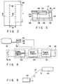
- FIG. 1 is a schematic view showing a flavor generation article according to an embodiment of the present invention.
- a flavor generation article 10 has a cylindrical casing 12 having such an outer diameter that the user can hold the casing 12 in his mouth.
- the casing 12 comprises a first portion 12a to be held by the user's mouth, and a second portion 12b for incorporating a power supply and the like.
- the two portions 12a and 12b are detachably connected to each other through a connecting portion 13 formed on a casing main body 14.
- the two portions 12a and 12b are electrically connected to each other through a cable 15 stored in a space formed in the casing main body 14 to correspond to the connecting portion 13.
- the main body 14 of the casing 12 is made of a material, e.g., a plastic, metallic, ceramic, or wooden material.
- a suction port 22 through which the user inhales the flavor is formed in the end portion of the first portion 12a of the casing 12.
- a plurality of air intake ports 24 for taking in air into the casing 12 are formed in the intermediate portion of the first portion 12a.
- a gas flow path 26 is defined in the casing 12 between the air intake ports 24 and the suction port 22.
- the air intake ports 24 can be formed to have an open area corresponding to a predetermined air intake amount.
- an adjusting ring 28 having a plurality of openings can be disposed on the casing 12 around the air intake ports 24. In this case, the amount of air flowing into the casing 12 can be adjusted by adjusting the position of the adjusting ring 28 with respect to the air intake ports 24.
- a throttle plate 21 having a throttle hole 20 at its center is disposed in the casing 12 to be located in the gas flow path 26.
- the throttle hole 20 serves to regulate air from the air intake ports 24 to flow along the surface of a ceramic heater 42 (to be described later).
- a material container 32 for storing a liquid material 36 for generating a flavor or the like to be inhaled by the user is detachably fixed in a space which is deep in the first portion 12a of the case and partitioned from the gas flow path 26 by a wall 31.
- the material container 32 stores the liquid material 36 in an amount corresponding to the discharge amount of a plurality of puffing operations of the user.
- the material container 32 can be mounted on the outer side of the casing main body 14. In this case, the head portion of the material container 32 may be inserted in the casing main body 14, or only discharge ports 35 (to be described later) may be inserted in the casing main body 14.
- the liquid material 36 contains at least a flavor substance.
- the liquid material 36 is an article used for enjoying only the flavor, e.g., menthol or caffeine, it can be a material that generates only the flavor.
- the liquid material 36 can contain a material which generates aerosol when heated.
- the material that generates aerosol alcohols, saccharide, or water, or a mixture of at least two of these components can be used.
- the alcohols used in this case are, e.g., glycerin or propylene glycol, or their mixture.
- the liquid material 36 can contain an extracted material and/or the constituent components of various types of natural materials in accordance with the application purpose.
- a tobacco component e.g., a tobacco extracted component or a tobacco smoke condensate component, may be contained in the liquid material 36.
- the material container 32 is formed with a discharge head 34 having the plurality of discharge ports 35 for discharging the liquid material 36 in a transverse direction of the casing 12.
- the discharge head 34 is arranged to be located closer to the suction port 22 than the throttle hole 20.
- a discharge drive portion 38 is disposed adjacent to the discharge ports 35 to discharge the liquid material 36 from the material container 32 through the discharge ports 35.
- the discharge head 34 and the discharge drive portion 38 comprise a liquid discharge mechanism (having the same principle as that of the method shown in Jpn. Pat. Appln. KOKOKU Publication No. 53-45698 and U.S.P. No. 3,596,275) utilizing a piezoelectric element.
- 10 discharge ports 35 are arranged for two rows, leading to a total of 20 discharge ports 35 in a region with a width W of about 2 mm and a length L of about 5 mm of the upper surface of the discharge head 34.
- the center of arrangement of the discharge ports 35 almost coincides with the center of the ceramic heater 42 (to be described later).
- FIG. 3 is an enlarged schematic view showing the discharge head 34 and discharge drive portion 38 taken along the line III - III of FIG. 2. More specifically, FIG. 3 shows a section corresponding to one row of the discharge ports 35. A section corresponding to the other row of the discharge ports 35 and the section shown in FIG. 3 are horizontally symmetrical.
- a frame 134 constituted by a plurality of components is stacked on a wiring board 132 to form recessed portions and holes to be filled with the liquid material 36.
- the recessed portions formed by the frame 134, excluding the plurality of discharge ports 35, are covered with a film 136.
- a liquid reservoir 146 is formed under the discharge ports 35 to temporarily store the liquid material 36.
- the bottom plate of the liquid reservoir 146 is constituted by an electrode 138 that serves as a vibration plate.
- the liquid material 36 from the material container 32 is supplied first through a narrow flow path 142, and flows from a plurality of suction holes 144, having a smaller diameter than that of the discharge ports 35, to reach the liquid reservoir 146.
- a control circuit 72 when the electrode 138 is operated to vibrate, the liquid material 36 is selectively discharged through the discharge ports 35 having a low resistance against the flow.
- the discharged liquid material 36 is supplied onto the ceramic heater 42 as a liquid drop LD.
- a known printer ink discharge mechanism can be modified and employed, e.g., a method disclosed in Jpn. Pat. Appln. KOKOKU Publication No. 61-59911 and the like wherein the process liquid is injected by bubbles generated by heating it, or a method disclosed in U.S.P. No. 3,060,429 and the like wherein the particles of the process liquid are electrified to perform electric field control.
- a discharge mechanism in which a liquid material 36 is a pressurized liquid and is controlled by opening/closing a valve disposed in a discharge ports 35 may be employed.
- the ceramic heater 42 is disposed in the gas flow path 26 to oppose the discharge ports 35.
- the ceramic heater 42 is fixed on the inner surface of the casing main body 14 through a support member 44.
- a gap 27 between the discharge ports 35 of the discharge head 34 and the ceramic heater 42 is set such that air from the throttle hole 20 can flow through it. Accordingly, air from the air intake ports 24 is directed by the throttle hole 20 to the gap 27 between the discharge ports 35 and ceramic heater 42.
- the ceramic heater 42 is constituted by a ceramic plate and a coated resistance heater on the ceramic plate, and is accordingly an integral member of a catch pan for receiving the splash of the material and a heating means for heating the catch pan.
- the catch pan and the heating means can be disposed as separate components.
- the porous layer 46 not only protects the surface of the ceramic heater 42 but also relaxes heat conduction from the ceramic heater 42, thereby stabilizing gasification of the splash of the material.
- the porous layer 46 can be formed of an organic compound, e.g., natural cellulose, a cellulose derivative, or an aramid resin, or an inorganic compound, e.g., carbon (including activated carbon), alumina, or silicon carbide.
- the porous layer 46 can have an arbitrary shape.
- the compound mentioned above may be formed as a formed body in advance, e.g., a film, a sheet, a plate, fabric, or unwoven fabric, and be used as the porous layer 46.
- the porous layer 46 may be formed by directly applying the powder of the component mentioned above on the ceramic heater 42.
- a cooling chamber 52 is formed between the ceramic heater 42 and the suction port 22 to constitute part of the gas flow path 26.
- Outer air inlet holes 54 are formed in the side wall of the casing main body 14 defining the cooling chamber.
- the gas heated by the ceramic heater 42 and containing a flavor is mixed with the outer air and cooled in the cooling chamber 52, and reaches the suction port 22.
- the outer air inlet holes 54 can be formed to have an open area corresponding to a predetermined air inlet amount.
- an adjusting ring 55 having a plurality of openings can be disposed on the casing 12 around the outer air inlet holes 54. In this case, the amount of outer air flowing into the cooling chamber 52 can be adjusted by adjusting the position of the adjusting ring 55 with respect to the outer air inlet holes 54.
- a filter 58 is disposed in the gas flow path 26 between the cooling chamber 52 and suction port 22 to cover the suction port 22.
- the pressure loss can be adjusted so that the flavor component can be inhaled with an appropriate pressure.
- the filter 58 can be made of a normal tobacco filter material made of cellulose acetate, pulp, or the like.
- a power supply 62 is detachably fixed in the second portion 12b of the casing 12.
- the power supply 62 is used to supply electric energy to the discharge drive portion 38, the ceramic heater 42, and the control circuit 72 (to be described later).
- the power supply 62 can be mounted in and removed from the casing main body 14 by opening/closing a cap 64 that closes the rear opening of the casing main body 14.
- the power supply 62 is preferably a DC power supply, e.g., a commercially available dry cell or rechargeable cell. However, the power supply 62 can be an AC power supply.
- the power supply 62 can be mounted on the outer side of the casing main body 14, or can be provided separately and connected to the casing main body 14 with a wire.
- the control circuit 72 for controlling the driving operation of the discharge drive portion 38 and the ceramic heater 42 is arranged between the power supply 62 and material container 32. As shown in FIG. 4, the control circuit 72 has a signal processing circuit 72a, a drive circuit 72b, and a power circuit 72c.
- the signal processing circuit 72a is connected to a sensor 73 for detecting the inhaling operation of the user and a manual ON/OFF switch 74.
- the drive circuit 72b is connected to the discharge drive portion 38 and the ceramic heater 42.
- the power circuit 72c is connected to the power supply 62.
- the sensor 73 for detecting the inhaling operation of the user is disposed around the casing main body 14 to be adjacent to the suction port 22.
- the sensor 73 has the same principle as that of a general strain type pressure-sensitive sensor for detecting a change in resistance or capacitance, a piezoelectric electromotive force, or the like, and generates an electrical signal upon detection of a pressure with which the user holds the casing 12 in his mouth.
- a swing vane type sensor to be described later
- a contact type sensor a lip sensor disclosed in Jpn. Pat. Appln. KOKAI Publication No. 5-212100, or the like can be used.
- the control circuit 72 Upon reception of a signal from the manual ON/OFF switch 74, or based on a signal from the sensor 73, the control circuit 72 starts the discharge drive portion 38 and the ceramic heater 42 at a timing to match the inhaling operation of the user, so that the liquid material is discharged and gasified.
- signal processing of the control circuit 72 and the way of control of the control circuit 72 can be known as analog control or two-position control, or their combination.
- the manual ON/OFF switch 74 is disposed on the side surface of the first portion 12a of the casing 12. When this article is not in use, the switch 74 may be manually switched to the OFF state, thereby forcibly stopping the discharge drive portion 38 and the heater 42.
- the manual switch 74 has the same mechanism as that of a general compact push switch, e.g., a micro limit switch having an electric contact.
- the user When the user performs simulated smoking or inhales the flavor by using the flavor generation article 10 shown in FIG. 1, first, the user turns on the manual switch 74, holds the first portion 12a of the casing 12 with his mouth, and performs an inhaling operation through the suction port 22. By this operation, the sensor 73 outputs an inhaling operation signal to the control circuit 72. Accordingly energization of the ceramic heater 42 is started under the control of the control circuit 72. Simultaneously, or with a lapse of a predetermined period after the start of energization, the discharge drive portion 38 is actuated.
- the liquid material 36 is then discharged from the discharge ports 35 and gasified as it is heated by the ceramic heater 42.
- the gasified material is mixed with main suction air which has been taken in from the air intake ports 24, passed through the throttle hole 20, and guided to a portion between the discharge ports 35 and ceramic heater 42, and is guided to the suction port 22.
- FIG. 6 shows a case wherein, in response to a signal from the sensor 73, the ceramic heater 42 is energized and heated and the liquid material 36 is discharged simultaneously.
- FIG. 7 shows a case wherein, in response to a signal from the sensor 73, the ceramic heater 42 is energized and preheated in advance, and with a lapse of a predetermined period of time, i.e., when the heater temperature has increased to a certain degree, the liquid material 36 is discharged.
- the amount of main suction air taken in from the air intake ports 24 and the amount of inlet air supplied from the outer air inlet holes 54 can be changed by adjusting the adjusting rings 28 and 60 during inhalation. Then, the taste of air containing the flavor and reaching the suction port 22 can be changed, so that the user can perform simulated smoking or inhalation of the flavor in accordance with the taste of his inhalation feeling.
- the casing 12 has a structure in which the first portion 12a storing the liquid material 36, the discharge head 34, the ceramic heater 42, and the like, and the second portion 12b storing the control circuit 72, the power supply 62, and the like are detachably connected to each other through the connecting portion 13.
- the first and second portions 12a and 12b are electrically connected to each other through the cable 15. Therefore, this flavor generation article 10 may be used with its first and second portions 12a and 12b being integrally connected to each other through the connecting portion 13, or may be used with its first and second portions 12a and 12b being separated from each other, as shown in FIG. 5. In the state shown in FIG.
- first and second portions 12a and 12b can be separated within a range allowed by the cable 15, for example, the user can place the second portion 12b in his pocket and hold only the first portion 12a in his mouth.
- the second portion 12b separated from the first portion 12a may be connected to an existing power supply, i.e., may be installed.
- glycerin As the flavor substance, some natural peppermint oil was used, and as the aerosol generation material to add smoke to the flavor, glycerin was used. Water was added to the natural peppermint oil and glycerin, thereby preparing a plurality of liquid materials 36 in which the water to glycerin concentration ratio changed in a range of about 2 : 98 to about 90 : 10. Aerosol containing a flavor substance obtained by heating each liquid material 36 was inhaled, by using the flavor generation article shown in FIG. 1, with a standard smoking condition of one cycle for about one minute in which 35 cc to 50 cc of aerosol were inhaled in one inhaling operation for about 2 seconds with an interval of about 58 seconds.
- liquid material 36 As a result, when a liquid material having a water to glycerin concentration ratio of 50 : 50 and prepared by adding some natural peppermint oil was employed as the liquid material 36, sufficiently high discharge stability was ensured, and physical satisfaction and requirement for a visually observed smoke amount upon inhalation were achieved to a certain degree. Therefore, in the following experiments, this liquid material was used as the liquid material 36. In the following experiments as well, inhalation was performed with the standard smoking condition of one cycle for about one minute in which 35 cc to 50 cc of aerosol were inhaled in one inhaling operation for about 2 seconds with an interval of about 58 seconds, and a discharge speed of about 2.5 mg/second was employed.
- the operation timings shown in FIGS. 6 and 7 were compared.
- the heater was heated from room temperature to about 400°C within 2 seconds.
- the liquid material 36 accumulated on the heater surface while the heater increased to the temperature that enabled gasification was gasified at once, and was condensed near the discharge ports 35 because of rapid expansion or flied in the form of a liquid drop because of bumping, thus decreasing the yield.
- the heater was preheated to about 140°C to 220°C during the preheat time at the timing shown in FIG. 7, and was thereafter heated to 420°C to 440°C within 2 seconds. In this case, the liquid material 36 was effectively gasified in an interlocked manner with discharge.
- the inhalation time of the user should correspond to a time period between the start and end of energization of the heater and discharge in FIG. 6, and should correspond to a time period between the start and end of energization of the heater, including the preheat time, in FIG. 7. Accordingly, the preheat time is preferably set within a range of about 0.1 second to 1 second in the standard smoking time, so that the user will not feel discomfort during inhalation, and it is required that the preheat time is not so high.
- the ceramic heater 42 and discharge ports 35 must oppose each other through a distance equal to or larger than about 2 mm.
- FIG. 8 is a schematic view showing a flavor generation article according to another embodiment of the present invention.
- the flavor generation article of this embodiment is similar to the flavor generation article shown in FIG. 1, but the orientation of discharge ports 35 of a discharge head 34 is different from that of the structure shown in FIG. 1 by 90° , so that the discharge ports 35 may be directed to a suction port 22. Accordingly, a ceramic heater 42 opposing the discharge ports 35 is set such that its direction is different from that of the structure shown in FIG. 1 by 90° . Since the discharge head 34 is arranged in a throttle hole 20, the substantial opening of the throttle hole 20 that serves as a gas flow path 26 is regulated by the size of both the throttle hole 20 and discharge head 34.
- FIG. 9 is a schematic view showing a flavor generation article according to still another embodiment of the present invention.
- the characteristic feature of the flavor generation article of this embodiment resides in that, first, a casing 12 cannot be separated into first and second portions 12a and 12b (see FIG. 1), and a liquid material 36, a discharge head 34, a ceramic heater 42, a power supply 62, a control unit 72, and the like are incorporated in one casing main body 14.
- a mouthpiece 16 is detachably mounted on the casing main body 14 through a connecting portion 18, and a suction port 22 is formed in the mouthpiece 16.
- the mouthpiece 16 is made of a material, e.g., a plastic or wood.
- As the connecting portion 18, a known structure, e.g., a screw or a fitting pair can be employed.
- a filter may be inserted in the casing main body 14 and served for use.
- the discharge head 34 provided to a material container 32 has one discharge port 35 which is oriented to discharge the liquid material 36 toward the suction port 22. Accordingly, the ceramic heater 42 opposing the discharge port 35 is oriented in the same direction as that of the structure shown in FIG. 8. No throttle plate 21 (see FIG. 1) is disposed in a gas flow path 26. Air that has flowed into the article flows on the ceramic heater 42 because it is regulated by a support member 44 supporting the ceramic heater 42.
- FIG. 10 is a schematic view showing a flavor generation article according to still another embodiment of the present invention.
- the flavor generation article of this embodiment is similar to the flavor generation article shown in FIG. 9 but is largely different from it in that its material container 32 is manually operated to discharge. For this reason, the material container 32 is connected to an operation lever 76 projecting outside a casing main body 14. When the lever 76 is depressed, a material corresponding to one puffing operation is emitted from a discharge port 35, and is supplied onto a ceramic heater 42 in the form of a liquid splash or liquid drop.
- a control circuit 72 receives a signal indicating a depressing operation of the lever 76, and supplies power to the ceramic heater 42 based on this signal to heat it, thereby gasifying the material splash.
- the lever 76 serves as both the discharge drive portion 38 for the flavor generation article and the sensor 73 for detecting the inhaling operation of the user that are shown in FIG. 1.
- the material container 32 is also connected to an injection port 82 for replenishing the material container 32 with a liquid material 36.
- the end portion of the injection port 82 is exposed outside the casing main body 14, and the liquid material can be injected and replenished to the material container 32 through this end portion.
- the material container 32 has a capacity sufficient for storing the liquid material 36 in an amount corresponding to the total discharge amount of a plurality of puffing operations of the user.
- the material container 32 need not be exchanged, but this flavor generation article can be used further continuously.
- a transparent inspection window 84 is formed in the side wall of the casing main body 14 to correspond to the material container 32. Accordingly, in this case, the material container 32 itself is also a transparent or translucent container.
- the inspection window 84 the user can know the timing at which the container should be replenished with the material.
- an electric remaining amount detection means includes a means for detecting a change in conductivity of the material container 32
- an example of the electric display means includes a means for using a light-emitting diode disposed on the outer surface of the casing main body 14.
- a method that optically detects the remaining amount by using a prism may also be employed.
- a power supply 62 is stored in a power supply holder 66 which is detachably mounted on the casing main body 14 through a connecting portion 68.
- a connecting portion 68 a known structure, e.g., a screw or a fitting pair, can be employed.
- FIG. 11 is a schematic view showing a flavor generation article according to still another embodiment of the present invention.
- the flavor generation article of this embodiment is similar to the flavor generation article shown in FIG. 10 but is different from it in that a discharge operation lever 76 is connected to an atomizer 86 provided to a discharge port 35.
- the atomizer 86 can supply a material corresponding to one puffing operation onto a ceramic heater 42 in the form of a liquid splash or liquid drop.
- a filler 56 is disposed in a cooling chamber 52.
- the cooling effect of the gasified flavor component can be promoted, and the pressure loss can be adjusted so that the flavor component can be inhaled with an appropriate pressure.
- the filler 56 for example, a fiber formed body made of cellulose acetate or pulp, or a particulate matter, e.g., glass or aluminum particles, can be used.
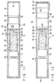
- FIG. 12 is a schematic view showing a flavor generation article according to still another embodiment of the present invention.
- the characteristic feature of the flavor generation article of this embodiment resides in that a formed body 92 of a solid material that generates a flavor or the like to be inhaled by the user is detachably disposed in a gas flow path 26 between a ceramic heater 42 and a cooling chamber 52.
- the formed body 92 of the solid material can contain an extracted material and/or the constituent components of various types of natural materials in accordance with the application purpose.
- the flavor material to be contained by the formed body 92 for example, menthol, caffeine, or a tobacco component, e.g., a tobacco extracted component or a tobacco smoke condensate component can be employed.
- the formed body 92 of the solid material has such a size that no gap is formed between it and the inner surface of a casing main body 14, a formed body 92 having good air permeability is used as the formed body 92.
- the gas flow path 26 between air intake ports 24 and a suction port 22 is formed to extend through the formed body 92.
- the size of the formed body 92 is set such that a gap is formed between the formed body 92 and the inner surface of the casing main body 14, a formed body 92 having poor or no air permeability can be used.
- the gas flow path 26 between the air intake ports 24 and suction port 22 is formed to extend through the gap between the formed body 92 and the inner surface of the casing main body 14.
- FIG. 13 is a schematic view showing a flavor generation article according to still another embodiment of the present invention.
- the flavor generation article of this embodiment is different from the flavor generation article shown in FIG. 12 in that a coil heater 94 for heating a formed body 92 is disposed around the formed body 92.
- the heater for heating the formed body 92 may be arranged in a hole formed in the formed body 92.
- the coil heater 94 together with a ceramic heater 42, can be controlled by a control circuit 72 so that power is supplied to them in accordance with the inhaling operation of the user.
- a control circuit 72 so that power is supplied to them in accordance with the inhaling operation of the user.
- the coil heater 94 may be kept heated when this article is in use, i.e., while a switch 74 is set in the ON state.
- the formed body 92 has such a size that a sufficiently large gap is formed between it and the inner surface of a casing main body 14. Accordingly, the major portion of a gas flow path 26 between air intake ports 24 and a suction port 22 extends through this gap.
- FIG. 14 is a schematic view showing a flavor generation article according to still another embodiment of the present invention.
- a swing vane type sensor is used to detect the inhaling operation of the user. More specifically, a swing vane 102 is disposed in a gas flow path 26 between a ceramic heater 42 and a cooling chamber 52. An orifice 112 having an opening 114 opposing the vane 102 is disposed in the gas flow path 26 between the ceramic heater 42 and the vane 102. The vane 102 is integrally connected to a conductive lever 104 which serves as the switch lever of the sensor circuit. An electric contact 108 of the sensor circuit is disposed on the inner surface of a casing main body 14 to oppose the conductive lever 104.
- the vane 102 and lever 104 are integrally, swingably, and axially supported on a support 106 on the inner surface of the casing main body 14, and is biased counterclockwise in FIG. 14 by a spring incorporated in the support 106. Accordingly, in an ordinary state, the vane 102 abuts against the orifice 112, and the lever 104 and contact 108 are not in contact with each other. However, when the user starts an inhaling operation, the gas flow, the flow velocity of which is increased by the orifice 112, pivots the vane 102 clockwise in FIG. 14, so that the lever 104 and contact 108 come into contact with each other.
- the inhaling operation signal of the user which is detected in this manner by the swing vane type sensor is transmitted to a control circuit 72. Based on this detection signal, a discharge drive portion 38 and the ceramic heater 42 can be controlled.
- FIG. 15 is a schematic view showing a flavor generation article according to still another embodiment of the present invention.
- the characteristic feature of the flavor generation article according to this embodiment resides in that a contact sensor is used in order to detect the inhaling operation of the user. More specifically, electric contacts 122 and 124 each made of an annular conductive plate are disposed at the center and the suction port-side end portion, respectively, of the outer surface of a casing 12. The electric contacts 122 and 124 constitute the switch of a sensor circuit. When the electric contacts 122 and 124 are connected to each other through a conductor, the sensor generates a detection signal. This state occurs when, e.g., two conditions that the user holds the electric contact 122 at the center with his hand and holds the suction port-side electric contact 124 in his mouth are satisfied simultaneously. The inhaling operation signal of the user which is detected by the contact sensor in this manner is transmitted to a control circuit 72. A discharge drive portion 38 and a ceramic heater 42 can be controlled based on this detection signal.
- FIG. 16 is a schematic view showing a flavor generation article according to still another embodiment of the present invention.
- the flavor generation article of this embodiment has discharge ports 35 of a discharge head 34 that are oriented in the same direction as that of the flavor generation article shown in FIG. 1, and a ceramic heater 42 opposing the discharge ports 35.
- a casing 12 cannot be separated into first and second portions 12a and 12b (see FIG. 1), and a liquid material 36, the discharge head 34, the ceramic heater 42, a power supply 62, a control unit 72, and the like are incorporated in one casing main body 14.
- a support member 44 of the ceramic heater 42 is formed to have a slit only at its central portion corresponding to the discharge head 34. Accordingly, air flowing through air intake ports 26 entirely passes through the gap between the discharge port 35 and the ceramic heater 42.
Landscapes
- Health & Medical Sciences (AREA)
- Engineering & Computer Science (AREA)
- Bioinformatics & Cheminformatics (AREA)
- Pulmonology (AREA)
- Anesthesiology (AREA)
- Biomedical Technology (AREA)
- Heart & Thoracic Surgery (AREA)
- Hematology (AREA)
- Life Sciences & Earth Sciences (AREA)
- Animal Behavior & Ethology (AREA)
- General Health & Medical Sciences (AREA)
- Public Health (AREA)
- Veterinary Medicine (AREA)
- Chemical & Material Sciences (AREA)
- Chemical Kinetics & Catalysis (AREA)
- General Chemical & Material Sciences (AREA)
- Disinfection, Sterilisation Or Deodorisation Of Air (AREA)
- Manufacture Of Tobacco Products (AREA)
- Cigarettes, Filters, And Manufacturing Of Filters (AREA)
- Seasonings (AREA)
Description
Claims (14)
- A flavor generation article characterized by comprising:a casting (12) having an air intake port (24) for taking in air therein and a suction port (22) through which a user inhales a flavor, and forming a gas flow path (26) between said intake port and said suction port;a material container (32) for storing a liquid material which contains at least a flavor substance and having a discharge port (35) for said material, said material container being mounted on said casing;discharge driving means (38) electrically operable for discharging said material from said container through said discharge port in the form of a liquid drop;gasifying means (42) disposed in said gas flow path to receive the liquid drop of said material discharged from said container by said discharge driving means and gasify said material by electrically heating the liquid drop;a power supply (62) for supplying electric energy to said discharge driving means and said gasifying means; andcontrol means (72) responsive to suction applied to the suction part (22) for selectively forming a state where said discharge driving means and said gasifying means operate in response to the suction by electric energy from said power supply.
- A flavor generation article according to claim 1, characterized by further comprising a sensor (73) for detecting an inhaling operation of the user, wherein said control means (72) controls, based on a signal from said sensor, said discharge driving means (38) and said gasifying means (42) so as to discharge said material from said container (32) and to generate heat by said gasifying means.
- A flavor generation article according to claim 2, characterized in that said sensor (73) comprises a pressure-sensitive sensor mounted on said casing (12) around said suction port (22).
- A flavor generation article according to claim 2 or 3, characterized in that said control means (72) controls said discharge driving means (38) and said gasifying means (42) based on the signal from said sensor (73) so that said discharge driving means and said gasifying means start operation at the same time.
- A flavor generation article according to claim 2 or 3, characterized in that said control means (72) controls said gasifying means (42) and said discharge driving means (38) based on the signal from said sensor (73) so as to preheat said gasifying means prior to discharge of said material.
- A flavor generation article according to any one of claims 1 to 5, characterized in that said control means (72) controls said gasifying means (42) and said discharge driving means (38) so that said discharge driving means and said gasifying means stop operation at the same time.
- A flavor generation article according to claim 1, characterized in that said power supply (62) is disposed in said casing (12).
- A flavor generation article according to claim 7, characterized in that said casing (12) is constituted by first and second portions (12a, 12b) that are electrically connected to each other through a cable (15), said gas flow path (26), said container (32), said discharge driving means (38), said gasifying means (42) being disposed in said first portion (12a), and said power supply (62) being disposed in said second portion (12b).
- A flavor generation article according to claim 8, characterized in that said first and second portions (12a, 12b) of said casing (12) are detachably connected to each other through a connecting portion (13).
- A flavor generation article according to any one of claims 1 to 9, characterized in that said gasifying means (42) comprises a porous layer (46), and the liquid drop of said material is supplied onto said porous layer.
- A flavor generation article according to any one of claims 1 to 10, characterized in that said gasifying means (42) is arranged to oppose said discharge port (35), and a throttle hole (20) for directing air flowing form said air intake port (24) toward a gap between said discharge port and said gasifying means is disposed in said gas flow path (26).
- A flavor generation article according to any one of claims 1 to 11, characterized in that said casing (12) is formed with an outer air inlet hole (54) in order to supply an outer air into said gas flow path (26) between said gasifying means (42) and said suction port (22).
- A flavor generation article according to any one of claims 1 to 12, characterized by further comprising a formed body (92) of a solid material containing at least a flavor substance and disposed in said gas flow path (26) so as to be located between said gasifying means (42) and said suction port (22).
- A flavor generation article according to claim 13, characterized by further comprising heating means (94) for heating said formed body (92).
Applications Claiming Priority (4)
| Application Number | Priority Date | Filing Date | Title |
|---|---|---|---|
| JP15563696 | 1996-06-17 | ||
| JP155636/96 | 1996-06-17 | ||
| JP15563696 | 1996-06-17 | ||
| PCT/JP1997/001953 WO1997048293A1 (en) | 1996-06-17 | 1997-06-09 | Flavor producing article |
Publications (3)
| Publication Number | Publication Date |
|---|---|
| EP0845220A1 EP0845220A1 (en) | 1998-06-03 |
| EP0845220A4 EP0845220A4 (en) | 1999-09-08 |
| EP0845220B1 true EP0845220B1 (en) | 2003-09-03 |
Family
ID=15610315
Family Applications (1)
| Application Number | Title | Priority Date | Filing Date |
|---|---|---|---|
| EP97925295A Expired - Lifetime EP0845220B1 (en) | 1996-06-17 | 1997-06-09 | Flavor producing article |
Country Status (7)
| Country | Link |
|---|---|
| EP (1) | EP0845220B1 (en) |
| JP (1) | JP3325028B2 (en) |
| KR (1) | KR100264617B1 (en) |
| CN (1) | CN1106812C (en) |
| DE (1) | DE69724559T2 (en) |
| TW (1) | TW360502B (en) |
| WO (1) | WO1997048293A1 (en) |
Cited By (42)
| Publication number | Priority date | Publication date | Assignee | Title |
|---|---|---|---|---|
| US8490628B2 (en) | 2004-04-14 | 2013-07-23 | Ruyan Investment (Holdings) Limited; | Electronic atomization cigarette |
| US8511318B2 (en) | 2003-04-29 | 2013-08-20 | Ruyan Investment (Holdings) Limited | Electronic cigarette |
| USD691765S1 (en) | 2013-01-14 | 2013-10-15 | Altria Client Services Inc. | Electronic smoking article |
| USD691766S1 (en) | 2013-01-14 | 2013-10-15 | Altria Client Services Inc. | Mouthpiece of a smoking article |
| USD695449S1 (en) | 2013-01-14 | 2013-12-10 | Altria Client Services Inc. | Electronic smoking article |
| US8689805B2 (en) | 2009-02-11 | 2014-04-08 | Fontem Holdings 1 B.V. | Electronic cigarette |
| US8881737B2 (en) | 2012-09-04 | 2014-11-11 | R.J. Reynolds Tobacco Company | Electronic smoking article comprising one or more microheaters |
| US8899238B2 (en) | 2006-10-18 | 2014-12-02 | R.J. Reynolds Tobacco Company | Tobacco-containing smoking article |
| US8910640B2 (en) | 2013-01-30 | 2014-12-16 | R.J. Reynolds Tobacco Company | Wick suitable for use in an electronic smoking article |
| US8910639B2 (en) | 2012-09-05 | 2014-12-16 | R. J. Reynolds Tobacco Company | Single-use connector and cartridge for a smoking article and related method |
| US8997753B2 (en) | 2012-01-31 | 2015-04-07 | Altria Client Services Inc. | Electronic smoking article |
| US9078473B2 (en) | 2011-08-09 | 2015-07-14 | R.J. Reynolds Tobacco Company | Smoking articles and use thereof for yielding inhalation materials |
| WO2015112750A1 (en) | 2014-01-22 | 2015-07-30 | E-Nicotine Technology, Inc. | Methods and devices for smoking urge relief |
| US9095175B2 (en) | 2010-05-15 | 2015-08-04 | R. J. Reynolds Tobacco Company | Data logging personal vaporizing inhaler |
| US9220302B2 (en) | 2013-03-15 | 2015-12-29 | R.J. Reynolds Tobacco Company | Cartridge for an aerosol delivery device and method for assembling a cartridge for a smoking article |
| US9259035B2 (en) | 2010-05-15 | 2016-02-16 | R. J. Reynolds Tobacco Company | Solderless personal vaporizing inhaler |
| US9277770B2 (en) | 2013-03-14 | 2016-03-08 | R. J. Reynolds Tobacco Company | Atomizer for an aerosol delivery device formed from a continuously extending wire and related input, cartridge, and method |
| US9289014B2 (en) | 2012-02-22 | 2016-03-22 | Altria Client Services Llc | Electronic smoking article and improved heater element |
| US9352288B2 (en) | 2010-05-15 | 2016-05-31 | Rai Strategic Holdings, Inc. | Vaporizer assembly and cartridge |
| US9423152B2 (en) | 2013-03-15 | 2016-08-23 | R. J. Reynolds Tobacco Company | Heating control arrangement for an electronic smoking article and associated system and method |
| US9451791B2 (en) | 2014-02-05 | 2016-09-27 | Rai Strategic Holdings, Inc. | Aerosol delivery device with an illuminated outer surface and related method |
| US9491974B2 (en) | 2013-03-15 | 2016-11-15 | Rai Strategic Holdings, Inc. | Heating elements formed from a sheet of a material and inputs and methods for the production of atomizers |
| US9532597B2 (en) | 2012-02-22 | 2017-01-03 | Altria Client Services Llc | Electronic smoking article |
| US9597466B2 (en) | 2014-03-12 | 2017-03-21 | R. J. Reynolds Tobacco Company | Aerosol delivery system and related method, apparatus, and computer program product for providing control information to an aerosol delivery device via a cartridge |
| KR101803983B1 (en) | 2009-10-27 | 2017-12-01 | 필립모리스 프로덕츠 에스.에이. | A smoking system having a liquid storage portion and improved airflow characteristics |
| US10028533B2 (en) | 2014-05-21 | 2018-07-24 | Philip Morris Products S.A. | Inductive heating device, aerosol delivery system comprising an inductive heating device, and method of operating same |
| US10034988B2 (en) | 2012-11-28 | 2018-07-31 | Fontem Holdings I B.V. | Methods and devices for compound delivery |
| EP3061359B1 (en) | 2006-05-16 | 2018-10-03 | Fontem Holdings 1 B.V. | Aerosol electronic cigarette |
| RU2675654C1 (en) * | 2013-10-29 | 2018-12-21 | Бритиш Америкэн Тобэкко (Инвестментс) Лимитед | Device for heating of smoking material |
| US10194693B2 (en) | 2013-09-20 | 2019-02-05 | Fontem Holdings 1 B.V. | Aerosol generating device |
| CN109714990A (en) * | 2016-09-14 | 2019-05-03 | 英美烟草(投资)有限公司 | Receiver section |
| RU2692733C1 (en) * | 2012-07-16 | 2019-06-27 | Никовентчерс Холдингс Лимитед | Electronic device for steam production |
| US10653186B2 (en) | 2013-11-12 | 2020-05-19 | VMR Products, LLC | Vaporizer, charger and methods of use |
| RU2744608C1 (en) * | 2015-12-28 | 2021-03-11 | Раи Стретеджик Холдингс, Инк. | Aerosol delivery device including casing and connector |
| EP3763230A4 (en) * | 2018-03-05 | 2021-10-27 | Japan Tobacco Inc. | Non-combustion heating-type smoking article |
| EP3833201A4 (en) * | 2019-10-11 | 2021-12-22 | KT&G Corporation | Aerosol generating device and method for showing the remaining amount of liquid composition using light source |
| USRE49114E1 (en) | 2011-06-28 | 2022-06-28 | Juul Labs, Inc. | Electronic cigarette with liquid reservoir |
| EP3808194B1 (en) * | 2008-04-30 | 2022-12-14 | Philip Morris Products S.A. | An electrically heated smoking system having a liquid storage portion |
| US11589621B2 (en) | 2017-05-23 | 2023-02-28 | Rai Strategic Holdings, Inc. | Heart rate monitor for an aerosol delivery device |
| US11647783B2 (en) | 2005-07-19 | 2023-05-16 | Juul Labs, Inc. | Devices for vaporization of a substance |
| US11904089B2 (en) | 2011-08-16 | 2024-02-20 | Juul Labs, Inc. | Devices for vaporization of a substance |
| US11980220B2 (en) | 2021-07-28 | 2024-05-14 | Rai Strategic Holdings, Inc. | Tobacco-containing smoking article |
Families Citing this family (352)
| Publication number | Priority date | Publication date | Assignee | Title |
|---|---|---|---|---|
| US6629524B1 (en) * | 2000-07-12 | 2003-10-07 | Ponwell Enterprises Limited | Inhaler |
| US20030051728A1 (en) * | 2001-06-05 | 2003-03-20 | Lloyd Peter M. | Method and device for delivering a physiologically active compound |
| GB2397007A (en) * | 2003-01-08 | 2004-07-14 | Jonathan Richard Swift | Smoking-type device for generating a vapour for inhalation |
| US9675109B2 (en) * | 2005-07-19 | 2017-06-13 | J. T. International Sa | Method and system for vaporization of a substance |
| FR2895644B1 (en) * | 2006-01-03 | 2008-05-16 | Didier Gerard Martzel | SUBSTITUTE OF CIGARETTE |
| AT503485B1 (en) * | 2006-03-31 | 2009-03-15 | Almak Vertrieb Gmbh | TASCHENINHALATOR |
| JP2008035742A (en) * | 2006-08-03 | 2008-02-21 | British American Tobacco Pacific Corporation | Evaporating apparatus |
| JP2008043290A (en) * | 2006-08-21 | 2008-02-28 | Tsukasa Matsumoto | Pipe having highly functional texture and pipe cartridge |
| DE102006047146A1 (en) * | 2006-10-05 | 2008-04-10 | Michael Calefice | Smokeless cigarette for inhaling thermally soluble aromatic materials and nicotine, has outer paper sleeve, which is connected with mouth piece |
| US8991402B2 (en) | 2007-12-18 | 2015-03-31 | Pax Labs, Inc. | Aerosol devices and methods for inhaling a substance and uses thereof |
| CN101455447B (en) * | 2008-01-16 | 2010-07-14 | 北京格林世界科技发展有限公司 | Electric atomizer for electric cigarette |
| WO2009155734A1 (en) * | 2008-06-27 | 2009-12-30 | Maas Bernard | A substitute cigarette |
| AT507187B1 (en) | 2008-10-23 | 2010-03-15 | Helmut Dr Buchberger | INHALER |
| CN101518361B (en) * | 2009-03-24 | 2010-10-06 | 北京格林世界科技发展有限公司 | High-simulation electronic cigarette |
| CN201445686U (en) * | 2009-06-19 | 2010-05-05 | 李文博 | High-frequency induction atomizing device |
| US8897628B2 (en) | 2009-07-27 | 2014-11-25 | Gregory D. Conley | Electronic vaporizer |
| US10857311B2 (en) | 2010-01-12 | 2020-12-08 | Omega Life Science Ltd. | Method and apparatus for producing fine concentrated aerosol |
| CN104839892B (en) | 2010-04-30 | 2020-01-21 | 富特姆 4 有限公司 | Electronic smoking device |
| US8757147B2 (en) | 2010-05-15 | 2014-06-24 | Minusa Holdings Llc | Personal vaporizing inhaler with internal light source |
| US10136672B2 (en) | 2010-05-15 | 2018-11-27 | Rai Strategic Holdings, Inc. | Solderless directly written heating elements |
| US11344683B2 (en) | 2010-05-15 | 2022-05-31 | Rai Strategic Holdings, Inc. | Vaporizer related systems, methods, and apparatus |
| US9743691B2 (en) | 2010-05-15 | 2017-08-29 | Rai Strategic Holdings, Inc. | Vaporizer configuration, control, and reporting |
| US10159278B2 (en) | 2010-05-15 | 2018-12-25 | Rai Strategic Holdings, Inc. | Assembly directed airflow |
| US9999250B2 (en) | 2010-05-15 | 2018-06-19 | Rai Strategic Holdings, Inc. | Vaporizer related systems, methods, and apparatus |
| JP2012005412A (en) * | 2010-06-24 | 2012-01-12 | Jbs:Kk | Chemical liquid used for atomizer, and atomizer |
| US20120042884A1 (en) * | 2010-08-20 | 2012-02-23 | Magic Herbal S.A.R.L. | Electronic atomization hookah |
| GB201016797D0 (en) * | 2010-10-06 | 2010-11-17 | British American Tobacco Co | Aerosol generator |
| EP2460423A1 (en) * | 2010-12-03 | 2012-06-06 | Philip Morris Products S.A. | An electrically heated aerosol generating system having improved heater control |
| EP2468118A1 (en) * | 2010-12-24 | 2012-06-27 | Philip Morris Products S.A. | An aerosol generating system with means for disabling a consumable |
| EP2672848A4 (en) * | 2011-02-09 | 2017-12-06 | SIS Resources, Ltd. | Variable power control electronic cigarette |
| AT510837B1 (en) * | 2011-07-27 | 2012-07-15 | Helmut Dr Buchberger | INHALATORKOMPONENTE |
| CN103491815B (en) | 2011-02-11 | 2016-01-20 | 巴特马克有限公司 | Inhalator assembly |
| JPWO2012117935A1 (en) * | 2011-03-01 | 2014-07-07 | 日本たばこ産業株式会社 | Stimulus presentation device |
| US9399110B2 (en) | 2011-03-09 | 2016-07-26 | Chong Corporation | Medicant delivery system |
| BR112013022757A2 (en) | 2011-03-09 | 2021-01-05 | Chong Corporation | DRUG DELIVERY SYSTEM |
| US8903228B2 (en) | 2011-03-09 | 2014-12-02 | Chong Corporation | Vapor delivery devices and methods |
| KR101540192B1 (en) * | 2011-08-19 | 2015-07-28 | 니뽄 다바코 산교 가부시키가이샤 | Aerosol aspirator |
| EP3892125A3 (en) | 2011-09-06 | 2022-01-05 | Nicoventures Trading Limited | Heating smokable material |
| CN103596458B (en) | 2011-09-06 | 2017-07-28 | 英美烟草(投资)有限公司 | Heat smokeable material |
| BR112013032558B1 (en) | 2011-09-06 | 2021-01-12 | British American Tobacco (Investments) Limited | apparatus for heating smokable material |
| UA111630C2 (en) | 2011-10-06 | 2016-05-25 | Сіс Рісорсез Лтд. | BURNING SYSTEM |
| AT511344B1 (en) | 2011-10-21 | 2012-11-15 | Helmut Dr Buchberger | INHALATORKOMPONENTE |
| US8820330B2 (en) | 2011-10-28 | 2014-09-02 | Evolv, Llc | Electronic vaporizer that simulates smoking with power control |
| WO2013083635A1 (en) * | 2011-12-07 | 2013-06-13 | Philip Morris Products S.A. | An aerosol generating device having airflow inlets |
| ES2661023T3 (en) * | 2011-12-08 | 2018-03-27 | Philip Morris Products S.A. | Aerosol generating device with adjustable air flow |
| ES2688362T3 (en) | 2011-12-08 | 2018-11-02 | Philip Morris Products S.A. | Aerosol generating device with air flow nozzle |
| UA112883C2 (en) | 2011-12-08 | 2016-11-10 | Філіп Морріс Продактс С.А. | DEVICE FOR THE FORMATION OF AEROSOL WITH A CAPILLARY BORDER LAYER |
| JP5807768B2 (en) * | 2011-12-23 | 2015-11-10 | 恵州市吉瑞科技有限公司深▲せん▼分公司 | Electronic cigarette suction nozzle |
| EP2609821A1 (en) * | 2011-12-30 | 2013-07-03 | Philip Morris Products S.A. | Method and apparatus for cleaning a heating element of aerosol-generating device |
| US20130255702A1 (en) | 2012-03-28 | 2013-10-03 | R.J. Reynolds Tobacco Company | Smoking article incorporating a conductive substrate |
| ES2886183T3 (en) * | 2012-04-12 | 2021-12-16 | Jt Int Sa | Aerosol Generating Devices |
| GB201207039D0 (en) | 2012-04-23 | 2012-06-06 | British American Tobacco Co | Heating smokeable material |
| CA2875632C (en) * | 2012-06-05 | 2017-01-17 | Kimree Hi-Tech Inc. | Electronic cigarette and its suction rod |
| US10004259B2 (en) | 2012-06-28 | 2018-06-26 | Rai Strategic Holdings, Inc. | Reservoir and heater system for controllable delivery of multiple aerosolizable materials in an electronic smoking article |
| GB2504074A (en) * | 2012-07-16 | 2014-01-22 | Nicoventures Holdings Ltd | Electronic cigarette |
| GB2504076A (en) | 2012-07-16 | 2014-01-22 | Nicoventures Holdings Ltd | Electronic smoking device |
| US10117460B2 (en) | 2012-10-08 | 2018-11-06 | Rai Strategic Holdings, Inc. | Electronic smoking article and associated method |
| US9854841B2 (en) | 2012-10-08 | 2018-01-02 | Rai Strategic Holdings, Inc. | Electronic smoking article and associated method |
| DE102012111476A1 (en) * | 2012-11-27 | 2014-05-28 | Leslaw Piasecki | Evaporator device for use as electronic cigarette for aromatic substances, has storage container for accommodating liquid substance to be evaporated, evaporation unit, and mouthpiece for receiving evaporated substance by user |
| US20140190496A1 (en) * | 2012-11-28 | 2014-07-10 | E-Nicotine Technology, Inc. | Methods and devices for compound delivery |
| CN202980149U (en) * | 2012-12-27 | 2013-06-12 | 深圳市康泓威科技有限公司 | Electronic cigarette |
| USD849993S1 (en) | 2013-01-14 | 2019-05-28 | Altria Client Services | Electronic smoking article |
| USD841231S1 (en) | 2013-01-14 | 2019-02-19 | Altria Client Services, Llc | Electronic vaping device mouthpiece |
| WO2014118286A2 (en) | 2013-01-30 | 2014-08-07 | Philip Morris Products S.A | Improved aerosol from tobacco |
| US10031183B2 (en) | 2013-03-07 | 2018-07-24 | Rai Strategic Holdings, Inc. | Spent cartridge detection method and system for an electronic smoking article |
| US9918495B2 (en) | 2014-02-28 | 2018-03-20 | Rai Strategic Holdings, Inc. | Atomizer for an aerosol delivery device and related input, aerosol production assembly, cartridge, and method |
| US9609893B2 (en) | 2013-03-15 | 2017-04-04 | Rai Strategic Holdings, Inc. | Cartridge and control body of an aerosol delivery device including anti-rotation mechanism and related method |
| US10098381B2 (en) | 2013-03-15 | 2018-10-16 | Altria Client Services Llc | Electronic smoking article |
| GB2515992A (en) | 2013-03-22 | 2015-01-14 | British American Tobacco Co | Heating smokeable material |
| CN204519358U (en) * | 2013-04-07 | 2015-08-05 | 吉瑞高新科技股份有限公司 | A kind of connector of electronic cigarette and electronic cigarette |
| CA2909323A1 (en) * | 2013-04-11 | 2014-10-16 | Kimree Hi-Tech Inc. | Electronic cigarette |
| GB2513638A (en) | 2013-05-02 | 2014-11-05 | Nicoventures Holdings Ltd | Electronic cigarette |
| GB2513637A (en) | 2013-05-02 | 2014-11-05 | Nicoventures Holdings Ltd | Electronic cigarette |
| GB2513639A (en) | 2013-05-02 | 2014-11-05 | Nicoventures Holdings Ltd | Electronic cigarette |
| US11229239B2 (en) | 2013-07-19 | 2022-01-25 | Rai Strategic Holdings, Inc. | Electronic smoking article with haptic feedback |
| US10390562B2 (en) | 2013-07-23 | 2019-08-27 | Altria Client Services Llc | Electronic smoking article |
| US9848645B2 (en) | 2013-07-24 | 2017-12-26 | Sis Resources Ltd. | Cartomizer structure for automated assembly |
| US9877511B2 (en) | 2013-07-24 | 2018-01-30 | Altria Client Services Llc | Electronic smoking article |
| US10172387B2 (en) | 2013-08-28 | 2019-01-08 | Rai Strategic Holdings, Inc. | Carbon conductive substrate for electronic smoking article |
| CN103932401B (en) * | 2013-09-29 | 2015-09-30 | 深圳麦克韦尔股份有限公司 | Electronic cigarette |
| JP6022700B2 (en) * | 2013-09-30 | 2016-11-09 | 日本たばこ産業株式会社 | Non-burning flavor inhaler |
| CN105636465B (en) * | 2013-09-30 | 2018-04-24 | 日本烟草产业株式会社 | Non-combustion-type fragrance extractor and container unit |
| JP6022702B2 (en) | 2013-09-30 | 2016-11-09 | 日本たばこ産業株式会社 | Non-burning flavor inhaler |
| CN109222242A (en) * | 2013-09-30 | 2019-01-18 | 日本烟草产业株式会社 | Non-combustion-type fragrance extractor and control method |
| BR302014001648S1 (en) | 2013-10-14 | 2015-06-09 | Altria Client Services Inc | Smoke Applied Configuration |
| US10292424B2 (en) * | 2013-10-31 | 2019-05-21 | Rai Strategic Holdings, Inc. | Aerosol delivery device including a pressure-based aerosol delivery mechanism |
| US10039321B2 (en) * | 2013-11-12 | 2018-08-07 | Vmr Products Llc | Vaporizer |
| DE102013112537A1 (en) * | 2013-11-14 | 2015-05-21 | Xeo International Ltd. | Electrically powered smoker's article and computer program |
| EP3068244A4 (en) | 2013-11-15 | 2017-07-05 | VMR Products, LLC | Vaporizer with cover sleeve |
| US9839237B2 (en) | 2013-11-22 | 2017-12-12 | Rai Strategic Holdings, Inc. | Reservoir housing for an electronic smoking article |
| EP3085256A4 (en) * | 2013-12-16 | 2017-09-27 | Kimree Hi-Tech Inc | Electronic cigarette control circuit, electronic cigarette, and control method for electronic cigarette |
| US10058129B2 (en) | 2013-12-23 | 2018-08-28 | Juul Labs, Inc. | Vaporization device systems and methods |
| UA118770C2 (en) * | 2013-12-31 | 2019-03-11 | Філіп Морріс Продактс С.А. | An aerosol-generating device, and a capsule for use in an aerosol-generating device |
| DE202014000267U1 (en) * | 2014-01-16 | 2015-04-20 | Xeo Holding GmbH | Evaporator module for an electronic cigarette |
| US9974334B2 (en) | 2014-01-17 | 2018-05-22 | Rai Strategic Holdings, Inc. | Electronic smoking article with improved storage of aerosol precursor compositions |
| ES2718075T3 (en) * | 2014-01-29 | 2019-06-27 | Japan Tobacco Inc | Flavor inhaler type without combustion |
| US10575558B2 (en) | 2014-02-03 | 2020-03-03 | Rai Strategic Holdings, Inc. | Aerosol delivery device comprising multiple outer bodies and related assembly method |
| US10709173B2 (en) | 2014-02-06 | 2020-07-14 | Juul Labs, Inc. | Vaporizer apparatus |
| US20150224268A1 (en) | 2014-02-07 | 2015-08-13 | R.J. Reynolds Tobacco Company | Charging Accessory Device for an Aerosol Delivery Device and Related System, Method, Apparatus, and Computer Program Product for Providing Interactive Services for Aerosol Delivery Devices |
| US9833019B2 (en) | 2014-02-13 | 2017-12-05 | Rai Strategic Holdings, Inc. | Method for assembling a cartridge for a smoking article |
| US9839238B2 (en) | 2014-02-28 | 2017-12-12 | Rai Strategic Holdings, Inc. | Control body for an electronic smoking article |
| USD788697S1 (en) | 2014-03-04 | 2017-06-06 | VMR Products, LLC | Battery portion for a vaporizer |
| USD763502S1 (en) | 2014-03-04 | 2016-08-09 | Vmr Products Llc | Cartomizer for a vaporizer |
| USD752278S1 (en) | 2014-03-07 | 2016-03-22 | VMR Products, LLC | Battery portion of a vaporizer |
| USD752280S1 (en) | 2014-03-07 | 2016-03-22 | VMR Products, LLC | Cartomizer for a vaporizer |
| USD749505S1 (en) | 2014-03-07 | 2016-02-16 | VMR Products, LLC | Charger for a vaporizer |
| US11696604B2 (en) | 2014-03-13 | 2023-07-11 | Rai Strategic Holdings, Inc. | Aerosol delivery device and related method and computer program product for controlling an aerosol delivery device based on input characteristics |
| CA2935967A1 (en) * | 2014-03-31 | 2015-10-08 | Philip Morris Products S.A. | Electrically heated aerosol-generating system |
| CN103859597A (en) * | 2014-04-02 | 2014-06-18 | 川渝中烟工业有限责任公司 | Cigarette free of combustion in heating process |
| US9877510B2 (en) | 2014-04-04 | 2018-01-30 | Rai Strategic Holdings, Inc. | Sensor for an aerosol delivery device |
| USD804090S1 (en) | 2014-04-08 | 2017-11-28 | VMR Products, LLC | Vaporizer with indicators |
| GB201407426D0 (en) | 2014-04-28 | 2014-06-11 | Batmark Ltd | Aerosol forming component |
| GB201407642D0 (en) | 2014-04-30 | 2014-06-11 | British American Tobacco Co | Aerosol-cooling element and arrangements for apparatus for heating a smokable material |
| USD750320S1 (en) | 2014-08-05 | 2016-02-23 | VMR Products, LLC | Vaporizer |
| KR101837885B1 (en) * | 2014-05-02 | 2018-03-12 | 니뽄 다바코 산교 가부시키가이샤 | Non-combustion-type flavor inhaler and computer-readable medium |
| US9924741B2 (en) | 2014-05-05 | 2018-03-27 | Rai Strategic Holdings, Inc. | Method of preparing an aerosol delivery device |
| TWI661782B (en) | 2014-05-21 | 2019-06-11 | 瑞士商菲利浦莫里斯製品股份有限公司 | Electrically heated aerosol-generating system,electrically heated aerosol-generating deviceand method of generating an aerosol |
| TWI666992B (en) | 2014-05-21 | 2019-08-01 | 瑞士商菲利浦莫里斯製品股份有限公司 | Aerosol-generating system and cartridge for usein the aerosol-generating system |
| TWI660685B (en) | 2014-05-21 | 2019-06-01 | 瑞士商菲利浦莫里斯製品股份有限公司 | Electrically heated aerosol-generating system and cartridge for use in such a system |
| US9955726B2 (en) | 2014-05-23 | 2018-05-01 | Rai Strategic Holdings, Inc. | Sealed cartridge for an aerosol delivery device and related assembly method |
| WO2015180018A1 (en) * | 2014-05-26 | 2015-12-03 | 深圳麦克韦尔股份有限公司 | Electronic cigarette |
| WO2015180058A1 (en) * | 2014-05-28 | 2015-12-03 | 吉瑞高新科技股份有限公司 | Electronic cigarette and air intake volume regulating method for electronic cigarette |
| US10888119B2 (en) | 2014-07-10 | 2021-01-12 | Rai Strategic Holdings, Inc. | System and related methods, apparatuses, and computer program products for controlling operation of a device based on a read request |
| US10058123B2 (en) | 2014-07-11 | 2018-08-28 | R. J. Reynolds Tobacco Company | Heater for an aerosol delivery device and methods of formation thereof |
| GB201412954D0 (en) | 2014-07-22 | 2014-09-03 | Nicoventures Holdings Ltd | Electronic vapour provision system |
| GB2528673B (en) | 2014-07-25 | 2020-07-01 | Nicoventures Holdings Ltd | Aerosol provision system |
| US10765144B2 (en) | 2014-08-21 | 2020-09-08 | Rai Strategic Holdings, Inc. | Aerosol delivery device including a moveable cartridge and related assembly method |
| US9913493B2 (en) | 2014-08-21 | 2018-03-13 | Rai Strategic Holdings, Inc. | Aerosol delivery device including a moveable cartridge and related assembly method |
| US9609895B2 (en) | 2014-08-21 | 2017-04-04 | Rai Strategic Holdings, Inc. | System and related methods, apparatuses, and computer program products for testing components of an aerosol delivery device |
| EP3000339B1 (en) * | 2014-09-23 | 2017-03-01 | Fontem Holdings 1 B.V. | Electronic smoking device |
| IL251512B (en) | 2014-10-13 | 2022-06-01 | Omega Life Science Ltd | Nebulizers |
| CN107072315B (en) * | 2014-10-15 | 2021-07-02 | 奥驰亚客户服务有限责任公司 | Electronic cigarette device and assembly thereof |
| GB201418817D0 (en) * | 2014-10-22 | 2014-12-03 | British American Tobacco Co | Apparatus and method for generating an inhalable medium, and a cartridge for use therewith |
| EP3212017B1 (en) | 2014-10-29 | 2021-06-16 | Altria Client Services LLC | Ethanol-free gel formulation cartridge for e-vaping device |
| US10849358B2 (en) | 2014-10-29 | 2020-12-01 | Altria Client Services Llc | E-vaping cartridge |
| US11051554B2 (en) | 2014-11-12 | 2021-07-06 | Rai Strategic Holdings, Inc. | MEMS-based sensor for an aerosol delivery device |
| CN204519374U (en) | 2015-04-20 | 2015-08-05 | 朱晓春 | Atomizer and the electronic cigarette of heat generating component is changed bottom the fluid injection of top |
| US10500600B2 (en) | 2014-12-09 | 2019-12-10 | Rai Strategic Holdings, Inc. | Gesture recognition user interface for an aerosol delivery device |
| EP3031339A1 (en) * | 2014-12-09 | 2016-06-15 | Xiaochun Zhu | Top refillable electronic cigarettes |
| GB2533135B (en) | 2014-12-11 | 2020-11-11 | Nicoventures Holdings Ltd | Aerosol provision systems |
| TWI674071B (en) | 2014-12-15 | 2019-10-11 | 瑞士商菲利浦莫里斯製品股份有限公司 | Aerosol-generating systems and methods for guiding an airflow inside an electrically heated aerosol-generating system |
| MX2017008761A (en) * | 2014-12-31 | 2018-03-23 | Utvg Global Ip B V | Personal electronic delivery system, atomizer assembly, use thereof and corresponding production method. |
| EP3042579A1 (en) * | 2015-01-09 | 2016-07-13 | Fontem Holdings 1 B.V. | Electronic smoking device |
| AU2016209328A1 (en) | 2015-01-22 | 2017-08-17 | Fontem Holdings 1 B.V. | Electronic vaporization devices |
| US10321711B2 (en) | 2015-01-29 | 2019-06-18 | Rai Strategic Holdings, Inc. | Proximity detection for an aerosol delivery device |
| JP6725524B2 (en) | 2015-02-27 | 2020-07-22 | ブリティッシュ アメリカン タバコ (インヴェストメンツ) リミテッドBritish American Tobacco (Investments) Limited | Cartridge, component and method for generating aspirable media |
| GB201503411D0 (en) | 2015-02-27 | 2015-04-15 | British American Tobacco Co | Apparatus and method for generating an inhalable medium, and a cartridge for use therewith |
| US10027016B2 (en) | 2015-03-04 | 2018-07-17 | Rai Strategic Holdings Inc. | Antenna for an aerosol delivery device |
| US9980516B2 (en) | 2015-03-09 | 2018-05-29 | Rai Strategic Holdings, Inc. | Aerosol delivery device including a wave guide and related method |
| CN110522090B (en) * | 2015-03-10 | 2022-11-29 | 日本烟草产业株式会社 | Optimization method for power supply output control of resistance heating element |
| US10172388B2 (en) | 2015-03-10 | 2019-01-08 | Rai Strategic Holdings, Inc. | Aerosol delivery device with microfluidic delivery component |
| GB201505593D0 (en) | 2015-03-31 | 2015-05-13 | British American Tobacco Co | Article for use with apparatus for heating smokable material |
| GB201505595D0 (en) | 2015-03-31 | 2015-05-13 | British American Tobacco Co | Cartridge for use with apparatus for heating smokeable material |
| GB2533874B (en) * | 2015-04-01 | 2019-02-20 | Electronic Cigarettes Ltd | Simulated smoking device |
| TWI581725B (en) * | 2015-04-02 | 2017-05-11 | 日本煙草產業股份有限公司 | Fragrance inhaler |
| CA2980426C (en) * | 2015-04-02 | 2020-09-15 | Japan Tobacco Inc. | Flavor inhaler |
| WO2016179376A1 (en) * | 2015-05-06 | 2016-11-10 | Altria Client Services Llc | Non-combustible smoking device and elements thereof |
| US11000069B2 (en) | 2015-05-15 | 2021-05-11 | Rai Strategic Holdings, Inc. | Aerosol delivery device and methods of formation thereof |
| US10238145B2 (en) | 2015-05-19 | 2019-03-26 | Rai Strategic Holdings, Inc. | Assembly substation for assembling a cartridge for a smoking article |
| HUE062936T2 (en) | 2015-05-29 | 2023-12-28 | Japan Tobacco Inc | Non-combustion flavor inhaler |
| US10362803B2 (en) | 2015-06-10 | 2019-07-30 | Evolv, Llc | Electronic vaporizer having reduced particle size |
| GB201511349D0 (en) | 2015-06-29 | 2015-08-12 | Nicoventures Holdings Ltd | Electronic aerosol provision systems |
| US9924743B2 (en) * | 2015-07-14 | 2018-03-27 | Tuanfang Liu | Electronic cigarette |
| US11504489B2 (en) | 2015-07-17 | 2022-11-22 | Rai Strategic Holdings, Inc. | Contained liquid system for refilling aerosol delivery devices |
| US10966460B2 (en) | 2015-07-17 | 2021-04-06 | Rai Strategic Holdings, Inc. | Load-based detection of an aerosol delivery device in an assembled arrangement |
| US10015987B2 (en) | 2015-07-24 | 2018-07-10 | Rai Strategic Holdings Inc. | Trigger-based wireless broadcasting for aerosol delivery devices |
| US10206429B2 (en) | 2015-07-24 | 2019-02-19 | Rai Strategic Holdings, Inc. | Aerosol delivery device with radiant heating |
| US11134544B2 (en) | 2015-07-24 | 2021-09-28 | Rai Strategic Holdings, Inc. | Aerosol delivery device with radiant heating |
| US11033054B2 (en) | 2015-07-24 | 2021-06-15 | Rai Strategic Holdings, Inc. | Radio-frequency identification (RFID) authentication system for aerosol delivery devices |
| US11924930B2 (en) | 2015-08-31 | 2024-03-05 | Nicoventures Trading Limited | Article for use with apparatus for heating smokable material |
| US20170055584A1 (en) | 2015-08-31 | 2017-03-02 | British American Tobacco (Investments) Limited | Article for use with apparatus for heating smokable material |
| US10034494B2 (en) | 2015-09-15 | 2018-07-31 | Rai Strategic Holdings, Inc. | Reservoir for aerosol delivery devices |
| GB201517471D0 (en) | 2015-10-02 | 2015-11-18 | British American Tobacco Co | Apparatus for generating an inhalable medium |
| US10058125B2 (en) | 2015-10-13 | 2018-08-28 | Rai Strategic Holdings, Inc. | Method for assembling an aerosol delivery device |
| EP3155908B1 (en) * | 2015-10-16 | 2018-12-05 | Fontem Holdings 1 B.V. | Electronic smoking device with adaptable atomizing chamber |
| PL3155910T3 (en) * | 2015-10-16 | 2020-12-28 | Fontem Holdings 1 B.V. | Electronic smoking device with two parallel flow paths having a constant total flow resistance |
| US10918134B2 (en) | 2015-10-21 | 2021-02-16 | Rai Strategic Holdings, Inc. | Power supply for an aerosol delivery device |
| US20170112194A1 (en) | 2015-10-21 | 2017-04-27 | Rai Strategic Holdings, Inc. | Rechargeable lithium-ion capacitor for an aerosol delivery device |
| US10582726B2 (en) | 2015-10-21 | 2020-03-10 | Rai Strategic Holdings, Inc. | Induction charging for an aerosol delivery device |
| US10201187B2 (en) | 2015-11-02 | 2019-02-12 | Rai Strategic Holdings, Inc. | User interface for an aerosol delivery device |
| MX2018004861A (en) * | 2015-11-02 | 2018-08-01 | Philip Morris Products Sa | An aerosol-generating system comprising a vibratable element. |
| US10820630B2 (en) | 2015-11-06 | 2020-11-03 | Rai Strategic Holdings, Inc. | Aerosol delivery device including a wirelessly-heated atomizer and related method |
| US9955733B2 (en) | 2015-12-07 | 2018-05-01 | Rai Strategic Holdings, Inc. | Camera for an aerosol delivery device |
| US10440992B2 (en) | 2015-12-07 | 2019-10-15 | Rai Strategic Holdings, Inc. | Motion sensing for an aerosol delivery device |
| US11291252B2 (en) | 2015-12-18 | 2022-04-05 | Rai Strategic Holdings, Inc. | Proximity sensing for an aerosol delivery device |
| US10051891B2 (en) | 2016-01-05 | 2018-08-21 | Rai Strategic Holdings, Inc. | Capacitive sensing input device for an aerosol delivery device |
| US10194694B2 (en) | 2016-01-05 | 2019-02-05 | Rai Strategic Holdings, Inc. | Aerosol delivery device with improved fluid transport |
| US10258086B2 (en) | 2016-01-12 | 2019-04-16 | Rai Strategic Holdings, Inc. | Hall effect current sensor for an aerosol delivery device |
| CA2920933C (en) * | 2016-01-20 | 2020-03-24 | Xiaochun Zhu | Ceramic vaporizer and electronic cigarettes having the ceramic vaporizer |
| US10104912B2 (en) | 2016-01-20 | 2018-10-23 | Rai Strategic Holdings, Inc. | Control for an induction-based aerosol delivery device |
| US10015989B2 (en) | 2016-01-27 | 2018-07-10 | Rai Strategic Holdings, Inc. | One-way valve for refilling an aerosol delivery device |
| US11412781B2 (en) | 2016-02-12 | 2022-08-16 | Rai Strategic Holdings, Inc. | Adapters for refilling an aerosol delivery device |
| KR101862453B1 (en) * | 2016-02-25 | 2018-05-29 | 김효선 | aerosol pen to writing in the air |
| US10455863B2 (en) | 2016-03-03 | 2019-10-29 | Altria Client Services Llc | Cartridge for electronic vaping device |
| US10433580B2 (en) | 2016-03-03 | 2019-10-08 | Altria Client Services Llc | Methods to add menthol, botanic materials, and/or non-botanic materials to a cartridge, and/or an electronic vaping device including the cartridge |
| DE102016002665A1 (en) * | 2016-03-08 | 2017-09-14 | Hauni Maschinenbau Gmbh | Electronic cigarette product and cartridge for an electronic cigarette product |
| US10368580B2 (en) | 2016-03-08 | 2019-08-06 | Altria Client Services Llc | Combined cartridge for electronic vaping device |
| US9936733B2 (en) | 2016-03-09 | 2018-04-10 | Rai Strategic Holdings, Inc. | Accessory configured to charge an aerosol delivery device and related method |
| US10357060B2 (en) | 2016-03-11 | 2019-07-23 | Altria Client Services Llc | E-vaping device cartridge holder |
| US10368581B2 (en) | 2016-03-11 | 2019-08-06 | Altria Client Services Llc | Multiple dispersion generator e-vaping device |
| US10375992B2 (en) * | 2016-03-16 | 2019-08-13 | Shenzhen Kanger Technology Co., Ltd | Tamper-proof locking mechanisms and electronic cigarettes having the same |
| US10264821B2 (en) | 2016-03-21 | 2019-04-23 | Altria Client Services Llc | Electronic vaping device |
| US10894142B2 (en) * | 2016-03-24 | 2021-01-19 | Trudell Medical International | Respiratory care system with electronic indicator |
| US11207478B2 (en) | 2016-03-25 | 2021-12-28 | Rai Strategic Holdings, Inc. | Aerosol production assembly including surface with micro-pattern |
| US10334880B2 (en) | 2016-03-25 | 2019-07-02 | Rai Strategic Holdings, Inc. | Aerosol delivery device including connector comprising extension and receptacle |
| US10098387B2 (en) | 2016-03-31 | 2018-10-16 | Altria Client Services Llc | Vaporizing assembly comprising a viewable heating element and delivery device for an aerosol-generating system |
| MX2018011461A (en) | 2016-03-31 | 2019-01-10 | Philip Morris Products Sa | Vaporizing assembly comprising a viewable heating element and liquid delivery device for an aerosol generating system. |
| US10440996B2 (en) | 2016-03-31 | 2019-10-15 | Altria Client Services Llc | Atomizing assembly for use in an aerosol-generating system |
| WO2017167169A1 (en) * | 2016-03-31 | 2017-10-05 | 常州聚为智能科技有限公司 | Battery assembly and electronic cigarette having the battery assembly |
| CN109924546B (en) * | 2016-03-31 | 2022-01-21 | 卓尔悦欧洲控股有限公司 | Battery device and electronic cigarette with same |
| US10905163B2 (en) | 2016-03-31 | 2021-02-02 | Altria Client Services Llc | Aerosol-generating system with pump |
| US10945462B2 (en) | 2016-04-12 | 2021-03-16 | Rai Strategic Holdings, Inc. | Detachable power source for an aerosol delivery device |
| US10333339B2 (en) | 2016-04-12 | 2019-06-25 | Rai Strategic Holdings, Inc. | Charger for an aerosol delivery device |
| US10028534B2 (en) | 2016-04-20 | 2018-07-24 | Rai Strategic Holdings, Inc. | Aerosol delivery device, and associated apparatus and method of formation thereof |
| SG11201808879YA (en) * | 2016-04-22 | 2018-11-29 | Jt Int Sa | Aerosol generating device with a laser |
| AU2017256084B2 (en) | 2016-04-27 | 2020-09-24 | Nicoventures Trading Limited | Electronic aerosol provision system and vaporizer therefor |
| US10405579B2 (en) | 2016-04-29 | 2019-09-10 | Rai Strategic Holdings, Inc. | Methods for assembling a cartridge for an aerosol delivery device, and associated systems and apparatuses |
| CN205947119U (en) * | 2016-06-03 | 2017-02-15 | 湖南中烟工业有限责任公司 | Electronic cigarette atomizer |
| CN105901775A (en) * | 2016-06-03 | 2016-08-31 | 深圳市合元科技有限公司 | Jet-type atomization device |
| US10959458B2 (en) | 2016-06-20 | 2021-03-30 | Rai Strategic Holdings, Inc. | Aerosol delivery device including an electrical generator assembly |
| US10085485B2 (en) | 2016-07-06 | 2018-10-02 | Rai Strategic Holdings, Inc. | Aerosol delivery device with a reservoir housing and a vaporizer assembly |
| US10405581B2 (en) | 2016-07-08 | 2019-09-10 | Rai Strategic Holdings, Inc. | Gas sensing for an aerosol delivery device |
| US10463078B2 (en) | 2016-07-08 | 2019-11-05 | Rai Strategic Holdings, Inc. | Aerosol delivery device with condensing and non-condensing vaporization |
| US10231485B2 (en) | 2016-07-08 | 2019-03-19 | Rai Strategic Holdings, Inc. | Radio frequency to direct current converter for an aerosol delivery device |
| US10617151B2 (en) | 2016-07-21 | 2020-04-14 | Rai Strategic Holdings, Inc. | Aerosol delivery device with a liquid transport element comprising a porous monolith and related method |
| US10602775B2 (en) | 2016-07-21 | 2020-03-31 | Rai Strategic Holdings, Inc. | Aerosol delivery device with a unitary reservoir and liquid transport element comprising a porous monolith and related method |
| EP3487323B1 (en) * | 2016-07-25 | 2020-09-30 | Philip Morris Products S.a.s. | Manufacturing a fluid permeable heater assembly with cap |
| GB201612945D0 (en) | 2016-07-26 | 2016-09-07 | British American Tobacco Investments Ltd | Method of generating aerosol |
| US11019847B2 (en) | 2016-07-28 | 2021-06-01 | Rai Strategic Holdings, Inc. | Aerosol delivery devices including a selector and related methods |
| US10765146B2 (en) | 2016-08-08 | 2020-09-08 | Rai Strategic Holdings, Inc. | Boost converter for an aerosol delivery device |
| CA3033621C (en) * | 2016-08-26 | 2022-06-21 | Japan Tobacco Inc. | Non-combustion flavor inhaler |
| JP6997768B2 (en) * | 2016-09-01 | 2022-02-10 | フィリップ・モーリス・プロダクツ・ソシエテ・アノニム | Suceptor assembly and aerosol-generating articles equipped with it |
| US11937647B2 (en) | 2016-09-09 | 2024-03-26 | Rai Strategic Holdings, Inc. | Fluidic control for an aerosol delivery device |
| US10080387B2 (en) | 2016-09-23 | 2018-09-25 | Rai Strategic Holdings, Inc. | Aerosol delivery device with replaceable wick and heater assembly |
| EP3520633A4 (en) * | 2016-10-05 | 2020-05-27 | Japan Tobacco Inc. | Flavor inhaler and atomizing unit |
| US10477896B2 (en) | 2016-10-12 | 2019-11-19 | Rai Strategic Holdings, Inc. | Photodetector for measuring aerosol precursor composition in an aerosol delivery device |
| GB201618481D0 (en) | 2016-11-02 | 2016-12-14 | British American Tobacco Investments Ltd | Aerosol provision article |
| JP6321118B1 (en) * | 2016-11-14 | 2018-05-09 | 株式会社トレードワークス | A solution for electronic cigarettes containing green tea extract |
| US10492530B2 (en) | 2016-11-15 | 2019-12-03 | Rai Strategic Holdings, Inc. | Two-wire authentication system for an aerosol delivery device |
| US10524508B2 (en) | 2016-11-15 | 2020-01-07 | Rai Strategic Holdings, Inc. | Induction-based aerosol delivery device |
| US9864947B1 (en) | 2016-11-15 | 2018-01-09 | Rai Strategic Holdings, Inc. | Near field communication for a tobacco-based article or package therefor |
| US11103012B2 (en) | 2016-11-17 | 2021-08-31 | Rai Strategic Holdings, Inc. | Satellite navigation for an aerosol delivery device |
| US10524509B2 (en) | 2016-11-18 | 2020-01-07 | Rai Strategic Holdings, Inc. | Pressure sensing for an aerosol delivery device |
| US10206431B2 (en) | 2016-11-18 | 2019-02-19 | Rai Strategic Holdings, Inc. | Charger for an aerosol delivery device |
| US10653183B2 (en) | 2016-11-18 | 2020-05-19 | Rai Strategic Holdings, Inc. | Power source for an aerosol delivery device |
| US10172392B2 (en) | 2016-11-18 | 2019-01-08 | Rai Strategic Holdings, Inc. | Humidity sensing for an aerosol delivery device |
| US10537137B2 (en) | 2016-11-22 | 2020-01-21 | Rai Strategic Holdings, Inc. | Rechargeable lithium-ion battery for an aerosol delivery device |
| US9993027B1 (en) * | 2016-12-06 | 2018-06-12 | Funai Electric Co., Ltd. | Heater element for a vaporization device |
| US11013266B2 (en) | 2016-12-09 | 2021-05-25 | Rai Strategic Holdings, Inc. | Aerosol delivery device sensory system including an infrared sensor and related method |
| US10433585B2 (en) | 2016-12-28 | 2019-10-08 | Altria Client Services Llc | Non-combustible smoking systems, devices and elements thereof |
| GB201700136D0 (en) | 2017-01-05 | 2017-02-22 | British American Tobacco Investments Ltd | Aerosol generating device and article |
| GB201700620D0 (en) | 2017-01-13 | 2017-03-01 | British American Tobacco Investments Ltd | Aerosol generating device and article |
| US10517326B2 (en) | 2017-01-27 | 2019-12-31 | Rai Strategic Holdings, Inc. | Secondary battery for an aerosol delivery device |
| US10827783B2 (en) | 2017-02-27 | 2020-11-10 | Rai Strategic Holdings, Inc. | Digital compass for an aerosol delivery device |
| US10674765B2 (en) | 2017-03-29 | 2020-06-09 | Rai Strategic Holdings, Inc. | Aerosol delivery device with improved atomizer |
| US10440995B2 (en) | 2017-03-29 | 2019-10-15 | Rai Strategic Holdings, Inc. | Aerosol delivery device including substrate with improved absorbency properties |
| TWI644625B (en) * | 2017-04-11 | 2018-12-21 | 研能科技股份有限公司 | Electronic cigarette |
| US10314340B2 (en) | 2017-04-21 | 2019-06-11 | Rai Strategic Holdings, Inc. | Refillable aerosol delivery device and related method |
| US10285444B2 (en) | 2017-04-27 | 2019-05-14 | Rai Strategic Holdings, Inc. | Aerosol delivery device including a ceramic wicking element |
| GB201707758D0 (en) | 2017-05-15 | 2017-06-28 | British American Tobacco Investments Ltd | Ground tobacco composition |
| GB201707769D0 (en) * | 2017-05-15 | 2017-06-28 | British American Tobacco Investments Ltd | Liquid tobacco extract |
| US11297876B2 (en) | 2017-05-17 | 2022-04-12 | Rai Strategic Holdings, Inc. | Aerosol delivery device |
| US10517330B2 (en) | 2017-05-23 | 2019-12-31 | RAI Stategic Holdings, Inc. | Heart rate monitor for an aerosol delivery device |
| TWI644626B (en) * | 2017-06-14 | 2018-12-21 | 研能科技股份有限公司 | Driving module of electronic cigarette |
| EP3646668B1 (en) | 2017-06-28 | 2022-03-09 | Philip Morris Products S.A. | Electrical heating assembly, aerosol-generating device and method for resistively heating an aerosol-forming substrate |
| JP7112427B2 (en) * | 2017-06-28 | 2022-08-03 | フィリップ・モーリス・プロダクツ・ソシエテ・アノニム | Electrical heating assembly, aerosol generator and method for resistively heating an aerosol-forming substrate |
| US10792443B2 (en) | 2017-06-30 | 2020-10-06 | Blackship Technologies Development Llc | Composite micro-vaporizer wicks |
| US10842197B2 (en) | 2017-07-12 | 2020-11-24 | Rai Strategic Holdings, Inc. | Detachable container for aerosol delivery having pierceable membrane |
| US10349674B2 (en) | 2017-07-17 | 2019-07-16 | Rai Strategic Holdings, Inc. | No-heat, no-burn smoking article |
| US11337456B2 (en) | 2017-07-17 | 2022-05-24 | Rai Strategic Holdings, Inc. | Video analytics camera system for an aerosol delivery device |
| US10505383B2 (en) | 2017-09-19 | 2019-12-10 | Rai Strategic Holdings, Inc. | Intelligent charger for an aerosol delivery device |
| US11039645B2 (en) | 2017-09-19 | 2021-06-22 | Rai Strategic Holdings, Inc. | Differential pressure sensor for an aerosol delivery device |
| US10157265B1 (en) | 2017-09-21 | 2018-12-18 | Rai Strategic Holdings, Inc. | Clinical study product dispensing device |
| US10506830B2 (en) * | 2017-09-22 | 2019-12-17 | Altria Client Services Llc | Air flow design for an e-vaping cartridge, method of making the e-vaping cartridge, and e-vaping device including the cartridge |
| US10660370B2 (en) | 2017-10-12 | 2020-05-26 | Rai Strategic Holdings, Inc. | Aerosol delivery device including a control body, an atomizer body, and a cartridge and related methods |
| DE102017123869B4 (en) * | 2017-10-13 | 2019-05-23 | Hauni Maschinenbau Gmbh | Liquid storage for an inhaler, in particular for an electronic cigarette product |
| US10314342B2 (en) * | 2017-10-20 | 2019-06-11 | Altria Client Services Llc | E-vaping device using a jet dispensing cartridge, and method of operating the e-vaping device |
| GB201717484D0 (en) * | 2017-10-24 | 2017-12-06 | Nicoventures Holdings Ltd | Electronic aerosol provision device |
| GB201717489D0 (en) | 2017-10-24 | 2017-12-06 | Nicoventures Holdings Ltd | Electronic aerosol provision device |
| GB201717480D0 (en) | 2017-10-24 | 2017-12-06 | Nicoventures Holdings Ltd | Electronic aerosol provision device with seal |
| GB201717486D0 (en) * | 2017-10-24 | 2017-12-06 | Nicoventures Holdings Ltd | Mechanism for hatch of electronic aerosol provision device |
| US10517332B2 (en) | 2017-10-31 | 2019-12-31 | Rai Strategic Holdings, Inc. | Induction heated aerosol delivery device |
| GB201718462D0 (en) * | 2017-11-08 | 2017-12-20 | British American Tobacco Investments Ltd | Vapour provision systems |
| GB201720338D0 (en) | 2017-12-06 | 2018-01-17 | British American Tobacco Investments Ltd | Component for an aerosol-generating apparatus |
| US10806181B2 (en) | 2017-12-08 | 2020-10-20 | Rai Strategic Holdings, Inc. | Quasi-resonant flyback converter for an induction-based aerosol delivery device |
| US10786010B2 (en) | 2017-12-15 | 2020-09-29 | Rai Strategic Holdings, Inc. | Aerosol delivery device with multiple aerosol delivery pathways |
| US10555558B2 (en) | 2017-12-29 | 2020-02-11 | Rai Strategic Holdings, Inc. | Aerosol delivery device providing flavor control |
| US10492540B2 (en) * | 2018-01-29 | 2019-12-03 | Tuanfang Liu | Electronic cigarette |
| US11019850B2 (en) | 2018-02-26 | 2021-06-01 | Rai Strategic Holdings, Inc. | Heat conducting substrate for electrically heated aerosol delivery device |
| US10813385B2 (en) | 2018-03-09 | 2020-10-27 | Rai Strategic Holdings, Inc. | Buck regulator with operational amplifier feedback for an aerosol delivery device |
| US10945465B2 (en) | 2018-03-15 | 2021-03-16 | Rai Strategic Holdings, Inc. | Induction heated susceptor and aerosol delivery device |
| US10798969B2 (en) | 2018-03-16 | 2020-10-13 | R. J. Reynolds Tobacco Company | Smoking article with heat transfer component |
| US11382356B2 (en) | 2018-03-20 | 2022-07-12 | Rai Strategic Holdings, Inc. | Aerosol delivery device with indexing movement |
| US11206864B2 (en) | 2018-03-26 | 2021-12-28 | Rai Strategic Holdings, Inc. | Aerosol delivery device providing flavor control |
| US10932490B2 (en) | 2018-05-16 | 2021-03-02 | Rai Strategic Holdings, Inc. | Atomizer and aerosol delivery device |
| US10959459B2 (en) | 2018-05-16 | 2021-03-30 | Rai Strategic Holdings, Inc. | Voltage regulator for an aerosol delivery device |
| US11191298B2 (en) | 2018-06-22 | 2021-12-07 | Rai Strategic Holdings, Inc. | Aerosol source member having combined susceptor and aerosol precursor material |
| US11094993B2 (en) | 2018-08-10 | 2021-08-17 | Rai Strategic Holdings, Inc. | Charge circuitry for an aerosol delivery device |
| US10939707B2 (en) | 2018-08-23 | 2021-03-09 | Rai Strategic Holdings, Inc. | Aerosol delivery device with segmented electrical heater |
| US11265974B2 (en) | 2018-08-27 | 2022-03-01 | Rai Strategic Holdings, Inc. | Aerosol delivery device with integrated thermal conductor |
| US11103013B2 (en) | 2018-09-07 | 2021-08-31 | Fontem Holdings 1 B.V. | Pivotable charging case for electronic smoking device |
| US11247005B2 (en) | 2018-09-26 | 2022-02-15 | Rai Strategic Holdings, Inc. | Aerosol delivery device with conductive inserts |
| US11753750B2 (en) | 2018-11-20 | 2023-09-12 | R.J. Reynolds Tobacco Company | Conductive aerosol generating composite substrate for aerosol source member |
| CN112996400A (en) | 2018-11-27 | 2021-06-18 | 菲利普莫里斯生产公司 | Sensor for device aerosol-generating system |
| US11547816B2 (en) | 2018-11-28 | 2023-01-10 | Rai Strategic Holdings, Inc. | Micropump for an aerosol delivery device |
| JP6522225B2 (en) * | 2018-12-19 | 2019-05-29 | 日本たばこ産業株式会社 | Method of manufacturing atomization unit, non-burning type flavor suction device, atomization unit and atomization unit package |
| US11096419B2 (en) | 2019-01-29 | 2021-08-24 | Rai Strategic Holdings, Inc. | Air pressure sensor for an aerosol delivery device |
| US11456480B2 (en) | 2019-02-07 | 2022-09-27 | Rai Strategic Holdings, Inc. | Non-inverting amplifier circuit for an aerosol delivery device |
| US11602164B2 (en) | 2019-03-14 | 2023-03-14 | Rai Strategic Holdings, Inc. | Aerosol delivery device with graded porosity from inner to outer wall surfaces |
| JP6621556B2 (en) * | 2019-03-28 | 2019-12-18 | 日本たばこ産業株式会社 | Non-burning flavor inhaler |
| JP6621557B2 (en) * | 2019-03-28 | 2019-12-18 | 日本たばこ産業株式会社 | Non-burning flavor inhaler |
| JP6621554B2 (en) * | 2019-03-28 | 2019-12-18 | 日本たばこ産業株式会社 | Non-burning flavor inhaler |
| JP6621555B2 (en) * | 2019-03-28 | 2019-12-18 | 日本たばこ産業株式会社 | Non-burning flavor inhaler |
| KR102252458B1 (en) | 2019-04-30 | 2021-05-14 | 주식회사 케이티앤지 | Aerosol generating device and operation method thereof |
| DE102019111218B4 (en) * | 2019-04-30 | 2023-08-17 | Helmar Schäfer | Smoking Instrument Replacement Product |
| US11517688B2 (en) | 2019-05-10 | 2022-12-06 | Rai Strategic Holdings, Inc. | Flavor article for an aerosol delivery device |
| US11589425B2 (en) | 2019-05-24 | 2023-02-21 | Rai Strategic Holdings, Inc. | Shape memory material for controlled liquid delivery in an aerosol delivery device |
| US10993472B2 (en) * | 2019-05-28 | 2021-05-04 | China Tobacco Yunnan Industrial Co., Ltd | Disposable double-channel cigarette and preparation method thereof |
| US11785991B2 (en) | 2019-10-04 | 2023-10-17 | Rai Strategic Holdings, Inc. | Use of infrared temperature detection in an aerosol delivery device |
| US11470689B2 (en) | 2019-10-25 | 2022-10-11 | Rai Strategic Holdings, Inc. | Soft switching in an aerosol delivery device |
| JP6678807B2 (en) * | 2019-11-15 | 2020-04-08 | 日本たばこ産業株式会社 | Non-burning type flavor inhaler and aerosol delivery method |
| US11259569B2 (en) | 2019-12-10 | 2022-03-01 | Rai Strategic Holdings, Inc. | Aerosol delivery device with downstream flavor cartridge |
| US11730193B2 (en) | 2019-12-15 | 2023-08-22 | Shaheen Innovations Holding Limited | Hookah device |
| KR20220141281A (en) | 2019-12-15 | 2022-10-19 | 샤힌 이노베이션즈 홀딩 리미티드 | Ultrasonic mist suction device |
| SI3837999T1 (en) | 2019-12-15 | 2022-10-28 | Shaheen Innovations Holding Limited | Mist inhaler devices |
| JP7480338B2 (en) | 2019-12-15 | 2024-05-09 | シャヒーン イノベーションズ ホールディング リミテッド | Ultrasonic Mist Inhaler |
| US11730191B2 (en) | 2019-12-15 | 2023-08-22 | Shaheen Innovations Holding Limited | Hookah device |
| EP3860696B1 (en) | 2019-12-15 | 2024-04-10 | Shaheen Innovations Holding Limited | Ultrasonic mist inhaler |
| US11666713B2 (en) | 2019-12-15 | 2023-06-06 | Shaheen Innovations Holding Limited | Mist inhaler devices |
| US11589610B2 (en) | 2019-12-15 | 2023-02-28 | Shaheen Innovations Holding Limited | Nicotine delivery device having a mist generator device and a driver device |
| US11607511B2 (en) | 2020-01-08 | 2023-03-21 | Nicoventures Trading Limited | Inductively-heated substrate tablet for aerosol delivery device |
| US11457665B2 (en) | 2020-01-16 | 2022-10-04 | Nicoventures Trading Limited | Susceptor arrangement for an inductively-heated aerosol delivery device |
| BR112022013067A2 (en) | 2020-01-30 | 2022-09-06 | Philip Morris Products Sa | AEROSOL GENERATING SYSTEM WITH LEAKAGE PREVENTION |
| KR20220119448A (en) * | 2020-01-30 | 2022-08-29 | 필립모리스 프로덕츠 에스.에이. | Aerosol-generating device with sensory media cartridge |
| JP6735943B2 (en) * | 2020-03-13 | 2020-08-05 | 日本たばこ産業株式会社 | Non-burning type flavor suction device |
| JP6737971B2 (en) * | 2020-03-13 | 2020-08-12 | 日本たばこ産業株式会社 | Non-combustion flavor inhaler |
| JP6737972B2 (en) * | 2020-03-13 | 2020-08-12 | 日本たばこ産業株式会社 | Non-combustion flavor inhaler |
| US11439189B2 (en) | 2020-04-28 | 2022-09-13 | Rai Strategic Holdings, Inc. | Mesh network charging for aerosol delivery devices |
| US11839240B2 (en) | 2020-04-29 | 2023-12-12 | Rai Strategic Holdings, Inc. | Piezo sensor for a power source |
| KR102639262B1 (en) * | 2020-07-23 | 2024-02-22 | 주식회사 케이티앤지 | Aerosol generating article, Cooling assembly for aerosol generating article, and Air volume control device |
| US11839239B2 (en) | 2020-08-12 | 2023-12-12 | DES Products Ltd. | Adjustable airflow cartridge for electronic vaporizer |
| US11707088B2 (en) | 2020-09-25 | 2023-07-25 | Rai Strategic Holdings, Inc. | Aroma delivery system for aerosol delivery device |
| JP1715888S (en) | 2020-10-30 | 2022-05-25 | Smoking aerosol generator | |
| JP1714442S (en) | 2020-10-30 | 2022-05-10 | Smoking aerosol generator | |
| JP1714441S (en) | 2020-10-30 | 2022-05-10 | Smoking aerosol generator | |
| JP1714440S (en) | 2020-10-30 | 2022-05-10 | Smoking aerosol generator | |
| JP1714443S (en) | 2020-10-30 | 2022-05-10 | Smoking aerosol generator | |
| USD990765S1 (en) | 2020-10-30 | 2023-06-27 | Nicoventures Trading Limited | Aerosol generator |
| US11889869B2 (en) | 2020-11-16 | 2024-02-06 | Rai Strategic Holdings, Inc. | Closed-loop control of temperature and pressure sensing for an aerosol provision device |
| USD989384S1 (en) | 2021-04-30 | 2023-06-13 | Nicoventures Trading Limited | Aerosol generator |
| WO2022243277A1 (en) * | 2021-05-20 | 2022-11-24 | Jt International Sa | Aerosol generation device with smoothed out pressure drop |
| US20230188901A1 (en) | 2021-12-15 | 2023-06-15 | Shaheen Innovations Holding Limited | Apparatus for transmitting ultrasonic waves |
Family Cites Families (14)
| Publication number | Priority date | Publication date | Assignee | Title |
|---|---|---|---|---|
| NL239226A (en) | 1958-05-16 | |||
| US3596275A (en) | 1964-03-25 | 1971-07-27 | Richard G Sweet | Fluid droplet recorder |
| US4303083A (en) * | 1980-10-10 | 1981-12-01 | Burruss Jr Robert P | Device for evaporation and inhalation of volatile compounds and medications |
| US4846199A (en) * | 1986-03-17 | 1989-07-11 | The Regents Of The University Of California | Smoking of regenerated tobacco smoke |
| US4735217A (en) * | 1986-08-21 | 1988-04-05 | The Procter & Gamble Company | Dosing device to provide vaporized medicament to the lungs as a fine aerosol |
| EP0358114A3 (en) * | 1988-09-08 | 1990-11-14 | R.J. Reynolds Tobacco Company | Aerosol delivery articles utilizing electrical energy |
| US4947874A (en) * | 1988-09-08 | 1990-08-14 | R. J. Reynolds Tobacco Company | Smoking articles utilizing electrical energy |
| US4945931A (en) | 1989-07-14 | 1990-08-07 | Brown & Williamson Tobacco Corporation | Simulated smoking device |
| US5144962A (en) | 1989-12-01 | 1992-09-08 | Philip Morris Incorporated | Flavor-delivery article |
| US5060671A (en) | 1989-12-01 | 1991-10-29 | Philip Morris Incorporated | Flavor generating article |
| US5261424A (en) | 1991-05-31 | 1993-11-16 | Philip Morris Incorporated | Control device for flavor-generating article |
| CA2061302C (en) | 1992-02-17 | 2000-04-18 | Jeffrey S. Hansen | Method of making synthetic diamond film |
| JPH06159911A (en) | 1992-11-27 | 1994-06-07 | Hitachi Ltd | Combination refrigerators |
| WO1995001137A1 (en) * | 1993-06-29 | 1995-01-12 | Voges Innovation Pty. Ltd. | Dispenser |
-
1997
- 1997-06-09 JP JP50265898A patent/JP3325028B2/en not_active Expired - Lifetime
- 1997-06-09 WO PCT/JP1997/001953 patent/WO1997048293A1/en active IP Right Grant
- 1997-06-09 KR KR1019980701138A patent/KR100264617B1/en not_active IP Right Cessation
- 1997-06-09 CN CN97190727A patent/CN1106812C/en not_active Expired - Fee Related
- 1997-06-09 DE DE69724559T patent/DE69724559T2/en not_active Expired - Fee Related
- 1997-06-09 EP EP97925295A patent/EP0845220B1/en not_active Expired - Lifetime
- 1997-06-16 TW TW086108333A patent/TW360502B/en active
Cited By (64)
| Publication number | Priority date | Publication date | Assignee | Title |
|---|---|---|---|---|
| US8511318B2 (en) | 2003-04-29 | 2013-08-20 | Ruyan Investment (Holdings) Limited | Electronic cigarette |
| US9326549B2 (en) | 2004-04-14 | 2016-05-03 | Fontem Holdings 1 B.V. | Electronic cigarette |
| US9717278B2 (en) | 2004-04-14 | 2017-08-01 | Fontem Holdings 1 B.V. | Electronic cigarette |
| US8490628B2 (en) | 2004-04-14 | 2013-07-23 | Ruyan Investment (Holdings) Limited; | Electronic atomization cigarette |
| US11647783B2 (en) | 2005-07-19 | 2023-05-16 | Juul Labs, Inc. | Devices for vaporization of a substance |
| EP3061359B1 (en) | 2006-05-16 | 2018-10-03 | Fontem Holdings 1 B.V. | Aerosol electronic cigarette |
| EP2789250B1 (en) | 2006-05-16 | 2018-12-26 | Fontem Holdings 1 B.V. | An aerosol electronic cigarette |
| US8899238B2 (en) | 2006-10-18 | 2014-12-02 | R.J. Reynolds Tobacco Company | Tobacco-containing smoking article |
| EP3808194B1 (en) * | 2008-04-30 | 2022-12-14 | Philip Morris Products S.A. | An electrically heated smoking system having a liquid storage portion |
| US8689805B2 (en) | 2009-02-11 | 2014-04-08 | Fontem Holdings 1 B.V. | Electronic cigarette |
| KR102080137B1 (en) | 2009-10-27 | 2020-02-21 | 필립모리스 프로덕츠 에스.에이. | A smoking system having a liquid storage portion and improved airflow characteristics |
| KR20210110730A (en) * | 2009-10-27 | 2021-09-08 | 필립모리스 프로덕츠 에스.에이. | A smoking system having a liquid storage portion and improved airflow characteristics |
| KR102471821B1 (en) | 2009-10-27 | 2022-11-29 | 필립모리스 프로덕츠 에스.에이. | A smoking system having a liquid storage portion and improved airflow characteristics |
| EP3845083B1 (en) * | 2009-10-27 | 2024-03-06 | Philip Morris Products S.A. | An electrically heated smoking system with a capillary wick |
| KR101803983B1 (en) | 2009-10-27 | 2017-12-01 | 필립모리스 프로덕츠 에스.에이. | A smoking system having a liquid storage portion and improved airflow characteristics |
| US11013265B2 (en) * | 2009-10-27 | 2021-05-25 | Philip Morris Usa Inc. | Smoking system having a liquid storage portion |
| KR20190040381A (en) * | 2009-10-27 | 2019-04-17 | 필립모리스 프로덕츠 에스.에이. | A smoking system having a liquid storage portion and improved airflow characteristics |
| US9427711B2 (en) | 2010-05-15 | 2016-08-30 | Rai Strategic Holdings, Inc. | Distal end inserted personal vaporizing inhaler cartridge |
| US9095175B2 (en) | 2010-05-15 | 2015-08-04 | R. J. Reynolds Tobacco Company | Data logging personal vaporizing inhaler |
| US9555203B2 (en) | 2010-05-15 | 2017-01-31 | Rai Strategic Holdings, Inc. | Personal vaporizing inhaler assembly |
| US9259035B2 (en) | 2010-05-15 | 2016-02-16 | R. J. Reynolds Tobacco Company | Solderless personal vaporizing inhaler |
| US9352288B2 (en) | 2010-05-15 | 2016-05-31 | Rai Strategic Holdings, Inc. | Vaporizer assembly and cartridge |
| USRE49114E1 (en) | 2011-06-28 | 2022-06-28 | Juul Labs, Inc. | Electronic cigarette with liquid reservoir |
| US9078473B2 (en) | 2011-08-09 | 2015-07-14 | R.J. Reynolds Tobacco Company | Smoking articles and use thereof for yielding inhalation materials |
| US11904089B2 (en) | 2011-08-16 | 2024-02-20 | Juul Labs, Inc. | Devices for vaporization of a substance |
| US9004073B2 (en) | 2012-01-31 | 2015-04-14 | Altria Client Services Inc. | Electronic cigarette |
| US9326547B2 (en) | 2012-01-31 | 2016-05-03 | Altria Client Services Llc | Electronic vaping article |
| US9282772B2 (en) | 2012-01-31 | 2016-03-15 | Altria Client Services Llc | Electronic vaping device |
| US8997754B2 (en) | 2012-01-31 | 2015-04-07 | Altria Client Services Inc. | Electronic cigarette |
| US9510623B2 (en) | 2012-01-31 | 2016-12-06 | Altria Client Services Llc | Electronic cigarette |
| US8997753B2 (en) | 2012-01-31 | 2015-04-07 | Altria Client Services Inc. | Electronic smoking article |
| US9532597B2 (en) | 2012-02-22 | 2017-01-03 | Altria Client Services Llc | Electronic smoking article |
| US9289014B2 (en) | 2012-02-22 | 2016-03-22 | Altria Client Services Llc | Electronic smoking article and improved heater element |
| RU2692733C1 (en) * | 2012-07-16 | 2019-06-27 | Никовентчерс Холдингс Лимитед | Electronic device for steam production |
| US8881737B2 (en) | 2012-09-04 | 2014-11-11 | R.J. Reynolds Tobacco Company | Electronic smoking article comprising one or more microheaters |
| US8910639B2 (en) | 2012-09-05 | 2014-12-16 | R. J. Reynolds Tobacco Company | Single-use connector and cartridge for a smoking article and related method |
| US10034988B2 (en) | 2012-11-28 | 2018-07-31 | Fontem Holdings I B.V. | Methods and devices for compound delivery |
| USD722196S1 (en) | 2013-01-14 | 2015-02-03 | Altria Client Services Inc. | Electronic smoking article |
| USD695449S1 (en) | 2013-01-14 | 2013-12-10 | Altria Client Services Inc. | Electronic smoking article |
| USD691766S1 (en) | 2013-01-14 | 2013-10-15 | Altria Client Services Inc. | Mouthpiece of a smoking article |
| USD691765S1 (en) | 2013-01-14 | 2013-10-15 | Altria Client Services Inc. | Electronic smoking article |
| US8910640B2 (en) | 2013-01-30 | 2014-12-16 | R.J. Reynolds Tobacco Company | Wick suitable for use in an electronic smoking article |
| US9277770B2 (en) | 2013-03-14 | 2016-03-08 | R. J. Reynolds Tobacco Company | Atomizer for an aerosol delivery device formed from a continuously extending wire and related input, cartridge, and method |
| US9220302B2 (en) | 2013-03-15 | 2015-12-29 | R.J. Reynolds Tobacco Company | Cartridge for an aerosol delivery device and method for assembling a cartridge for a smoking article |
| US9491974B2 (en) | 2013-03-15 | 2016-11-15 | Rai Strategic Holdings, Inc. | Heating elements formed from a sheet of a material and inputs and methods for the production of atomizers |
| US9423152B2 (en) | 2013-03-15 | 2016-08-23 | R. J. Reynolds Tobacco Company | Heating control arrangement for an electronic smoking article and associated system and method |
| US10194693B2 (en) | 2013-09-20 | 2019-02-05 | Fontem Holdings 1 B.V. | Aerosol generating device |
| RU2675654C1 (en) * | 2013-10-29 | 2018-12-21 | Бритиш Америкэн Тобэкко (Инвестментс) Лимитед | Device for heating of smoking material |
| US10653186B2 (en) | 2013-11-12 | 2020-05-19 | VMR Products, LLC | Vaporizer, charger and methods of use |
| US10736360B2 (en) | 2013-11-12 | 2020-08-11 | Vmr Products Llc | Vaporizer, charger and methods of use |
| US11051557B2 (en) | 2013-11-12 | 2021-07-06 | VMR Products, LLC | Vaporizer |
| US11606981B2 (en) | 2013-11-12 | 2023-03-21 | Vmr Products Llc | Vaporizer |
| EP3698832A1 (en) | 2014-01-22 | 2020-08-26 | Fontem Holdings 1 B.V. | Methods and devices for smoking urge relief |
| WO2015112750A1 (en) | 2014-01-22 | 2015-07-30 | E-Nicotine Technology, Inc. | Methods and devices for smoking urge relief |
| US9451791B2 (en) | 2014-02-05 | 2016-09-27 | Rai Strategic Holdings, Inc. | Aerosol delivery device with an illuminated outer surface and related method |
| US9597466B2 (en) | 2014-03-12 | 2017-03-21 | R. J. Reynolds Tobacco Company | Aerosol delivery system and related method, apparatus, and computer program product for providing control information to an aerosol delivery device via a cartridge |
| US10028533B2 (en) | 2014-05-21 | 2018-07-24 | Philip Morris Products S.A. | Inductive heating device, aerosol delivery system comprising an inductive heating device, and method of operating same |
| RU2744608C1 (en) * | 2015-12-28 | 2021-03-11 | Раи Стретеджик Холдингс, Инк. | Aerosol delivery device including casing and connector |
| CN109714990A (en) * | 2016-09-14 | 2019-05-03 | 英美烟草(投资)有限公司 | Receiver section |
| US11589621B2 (en) | 2017-05-23 | 2023-02-28 | Rai Strategic Holdings, Inc. | Heart rate monitor for an aerosol delivery device |
| EP3763230A4 (en) * | 2018-03-05 | 2021-10-27 | Japan Tobacco Inc. | Non-combustion heating-type smoking article |
| EP3833201A4 (en) * | 2019-10-11 | 2021-12-22 | KT&G Corporation | Aerosol generating device and method for showing the remaining amount of liquid composition using light source |
| US11930858B2 (en) | 2019-10-11 | 2024-03-19 | Kt&G Corporation | Aerosol generating device and method for showing the remaining amount of liquid composition using light source |
| US11980220B2 (en) | 2021-07-28 | 2024-05-14 | Rai Strategic Holdings, Inc. | Tobacco-containing smoking article |
Also Published As
| Publication number | Publication date |
|---|---|
| DE69724559D1 (en) | 2003-10-09 |
| WO1997048293A1 (en) | 1997-12-24 |
| JP3325028B2 (en) | 2002-09-17 |
| EP0845220A1 (en) | 1998-06-03 |
| CN1106812C (en) | 2003-04-30 |
| KR100264617B1 (en) | 2000-09-01 |
| EP0845220A4 (en) | 1999-09-08 |
| DE69724559T2 (en) | 2004-07-15 |
| TW360502B (en) | 1999-06-11 |
| CN1196660A (en) | 1998-10-21 |
| KR19990037661A (en) | 1999-05-25 |
Similar Documents
| Publication | Publication Date | Title |
|---|---|---|
| EP0845220B1 (en) | Flavor producing article | |
| KR100289448B1 (en) | Flavor generator | |
| JP2984657B2 (en) | Flavor generator | |
| US20050016550A1 (en) | Electronic cigarette | |
| JP2020005643A (en) | Aerosol delivery device including bubble jet head and related method | |
| JP3768646B2 (en) | Flavor suction supplies | |
| ES2613050T3 (en) | Liquid vaporization device for inhalation | |
| WO2005099494A1 (en) | An aerosol electronic cigarette | |
| UA127489C2 (en) | Shisha cartridge | |
| JP2005058421A (en) | Electronic inhalator | |
| US20210321662A1 (en) | Shisha cartridge with absorbent carrier | |
| US20230043438A1 (en) | Device for heating aerosol-forming substrate with air preheat | |
| KR102593728B1 (en) | Aerosol-generating apparatus based on ultrasound and cartridge recognition method thereof | |
| US20230000143A1 (en) | Aerosol-generating device with piercing assembly | |
| KR20230108321A (en) | Aerosol generator with humidity sensor and humidifier | |
| RU2815299C1 (en) | Hookah device with possibility of perforated cartridge | |
| RU2806171C2 (en) | Aerosol delivery device containing bubble-jet head, and related method | |
| KR102396395B1 (en) | Aerosol delivering device and aerosol generating device with the same | |
| RU2805911C2 (en) | Hookah cartridge | |
| RU2812954C1 (en) | Aerosol generating device with leakage prevention | |
| US20230000145A1 (en) | Shisha device configured to perforate a cartridge | |
| EP4362720A1 (en) | Method for cleaning an aerosol generating apparatus using inkjet technology | |
| JP2023509123A (en) | aerosol generator |
Legal Events
| Date | Code | Title | Description |
|---|---|---|---|
| PUAI | Public reference made under article 153(3) epc to a published international application that has entered the european phase |
Free format text: ORIGINAL CODE: 0009012 |
|
| 17P | Request for examination filed |
Effective date: 19980223 |
|
| AK | Designated contracting states |
Kind code of ref document: A1 Designated state(s): DE FR GB |
|
| RIN1 | Information on inventor provided before grant (corrected) |
Inventor name: BANDAI, TAKESHI-JAPAN TOBACCO INC. ENG. R+DCENTER Inventor name: SASAKI, HIROSHI-JAPAN TOBACCO INC. ENG. R+DCENTER Inventor name: KOBAYASHI, TAKESHI-JAPAN TOBACCO INC. ENGIN. Inventor name: TAKEUCHI, MANABU-JAPAN TOBACCO INC. Inventor name: SUSA, MASAYUKI-JAPAN TOBACCO INC. |
|
| A4 | Supplementary search report drawn up and despatched |
Effective date: 19990722 |
|
| AK | Designated contracting states |
Kind code of ref document: A4 Designated state(s): DE FR GB |
|
| 17Q | First examination report despatched |
Effective date: 20020517 |
|
| GRAH | Despatch of communication of intention to grant a patent |
Free format text: ORIGINAL CODE: EPIDOS IGRA |
|
| GRAH | Despatch of communication of intention to grant a patent |
Free format text: ORIGINAL CODE: EPIDOS IGRA |
|
| GRAA | (expected) grant |
Free format text: ORIGINAL CODE: 0009210 |
|
| AK | Designated contracting states |
Kind code of ref document: B1 Designated state(s): DE FR GB |
|
| REG | Reference to a national code |
Ref country code: GB Ref legal event code: FG4D |
|
| REF | Corresponds to: |
Ref document number: 69724559 Country of ref document: DE Date of ref document: 20031009 Kind code of ref document: P |
|
| PG25 | Lapsed in a contracting state [announced via postgrant information from national office to epo] |
Ref country code: GB Free format text: LAPSE BECAUSE OF NON-PAYMENT OF DUE FEES Effective date: 20040609 |
|
| ET | Fr: translation filed | ||
| PLBE | No opposition filed within time limit |
Free format text: ORIGINAL CODE: 0009261 |
|
| STAA | Information on the status of an ep patent application or granted ep patent |
Free format text: STATUS: NO OPPOSITION FILED WITHIN TIME LIMIT |
|
| 26N | No opposition filed |
Effective date: 20040604 |
|
| PG25 | Lapsed in a contracting state [announced via postgrant information from national office to epo] |
Ref country code: DE Free format text: LAPSE BECAUSE OF NON-PAYMENT OF DUE FEES Effective date: 20050101 |
|
| GBPC | Gb: european patent ceased through non-payment of renewal fee |
Effective date: 20040609 |
|
| PG25 | Lapsed in a contracting state [announced via postgrant information from national office to epo] |
Ref country code: FR Free format text: LAPSE BECAUSE OF NON-PAYMENT OF DUE FEES Effective date: 20050228 |
|
| REG | Reference to a national code |
Ref country code: FR Ref legal event code: ST |