EP0844310B1 - Installation de décrassage des plongeurs d'une cuve de traitement sous vide de l'acier liquide - Google Patents
Installation de décrassage des plongeurs d'une cuve de traitement sous vide de l'acier liquide Download PDFInfo
- Publication number
- EP0844310B1 EP0844310B1 EP97402772A EP97402772A EP0844310B1 EP 0844310 B1 EP0844310 B1 EP 0844310B1 EP 97402772 A EP97402772 A EP 97402772A EP 97402772 A EP97402772 A EP 97402772A EP 0844310 B1 EP0844310 B1 EP 0844310B1
- Authority
- EP
- European Patent Office
- Prior art keywords
- fingers
- nozzles
- deskulling
- frame
- installation according
- Prior art date
- Legal status (The legal status is an assumption and is not a legal conclusion. Google has not performed a legal analysis and makes no representation as to the accuracy of the status listed.)
- Expired - Lifetime
Links
Images



Classifications
-
- F—MECHANICAL ENGINEERING; LIGHTING; HEATING; WEAPONS; BLASTING
- F27—FURNACES; KILNS; OVENS; RETORTS
- F27D—DETAILS OR ACCESSORIES OF FURNACES, KILNS, OVENS OR RETORTS, IN SO FAR AS THEY ARE OF KINDS OCCURRING IN MORE THAN ONE KIND OF FURNACE
- F27D99/00—Subject matter not provided for in other groups of this subclass
-
- C—CHEMISTRY; METALLURGY
- C21—METALLURGY OF IRON
- C21C—PROCESSING OF PIG-IRON, e.g. REFINING, MANUFACTURE OF WROUGHT-IRON OR STEEL; TREATMENT IN MOLTEN STATE OF FERROUS ALLOYS
- C21C7/00—Treating molten ferrous alloys, e.g. steel, not covered by groups C21C1/00 - C21C5/00
- C21C7/10—Handling in a vacuum
-
- F—MECHANICAL ENGINEERING; LIGHTING; HEATING; WEAPONS; BLASTING
- F27—FURNACES; KILNS; OVENS; RETORTS
- F27D—DETAILS OR ACCESSORIES OF FURNACES, KILNS, OVENS OR RETORTS, IN SO FAR AS THEY ARE OF KINDS OCCURRING IN MORE THAN ONE KIND OF FURNACE
- F27D3/00—Charging; Discharging; Manipulation of charge
- F27D2003/0034—Means for moving, conveying, transporting the charge in the furnace or in the charging facilities
- F27D2003/0054—Means to move molten metal, e.g. electromagnetic pump
-
- F—MECHANICAL ENGINEERING; LIGHTING; HEATING; WEAPONS; BLASTING
- F27—FURNACES; KILNS; OVENS; RETORTS
- F27D—DETAILS OR ACCESSORIES OF FURNACES, KILNS, OVENS OR RETORTS, IN SO FAR AS THEY ARE OF KINDS OCCURRING IN MORE THAN ONE KIND OF FURNACE
- F27D25/00—Devices or methods for removing incrustations, e.g. slag, metal deposits, dust; Devices or methods for preventing the adherence of slag
-
- F—MECHANICAL ENGINEERING; LIGHTING; HEATING; WEAPONS; BLASTING
- F27—FURNACES; KILNS; OVENS; RETORTS
- F27D—DETAILS OR ACCESSORIES OF FURNACES, KILNS, OVENS OR RETORTS, IN SO FAR AS THEY ARE OF KINDS OCCURRING IN MORE THAN ONE KIND OF FURNACE
- F27D3/00—Charging; Discharging; Manipulation of charge
- F27D3/14—Charging or discharging liquid or molten material
Definitions
- the subject of the present invention is a scouring installation of divers from a tank vacuum treatment of liquid steel.
- a tank connected to a pumping means and provided, at its lower part, two vertical divers and parallel, each with an internal channel ensuring communication between the internal part of the tank and the outside of said tank.
- Liquid steel treatment is carried out by putting the liquid steel in a pocket, then immersing the plungers in liquid steel, pumping the atmosphere inside the tank which causes the liquid steel to rise through the channels of divers in the tank and by injecting a gas into one of the channels thus causing intense circulation of liquid steel in the divers' channels.
- the behavior of the refractory material divers is essential to the quality of the metallurgical treatment and a deficiency in this area often leads to a loss of efficiency in terms of rate liquid steel recirculation and therefore a loss sensitive productivity.
- the first technique consists in carrying out the scouring from the ground using a shovel striking the refractory material and the gangue deposited when the height of the divers from the floor is low enough.
- the second technique consists in carrying out the scouring from a work platform and at means of a set of struts if the distance between divers and the work floor is too large.
- the gunning is done the most often from a cart and using a lance manual projection.
- Document JP-A-62151260 describes an installation cleaning of tubular divers made of refractory material a liquid steel vacuum treatment tank comprising a tank bottom supporting the plungers arranged vertically and delimiting between them an intermediate space.
- This installation includes a movable frame horizontally and vertically, comprising, in its part upper, means for simultaneously scraping the surface external of the vacuum treatment tank plungers.
- the object of the invention is to propose an installation mechanical cleaning of divers from a tank treatment of the liquid steel which allows to act quickly and regularly on the still hot fouling matrix, therefore flowable and limit the uncontrolled growth of this gangue, while avoiding that the operators are found in the risk zone.
- the subject of the invention is therefore an installation cleaning of tubular divers made of refractory material a liquid steel vacuum treatment tank comprising a bottom of the tank supporting the arranged divers vertically and delimiting between them an intermediate space, the installation including a movable frame horizontally and vertically and comprising at its part upper scraping means from bottom to top and simultaneous of the external surface of said plungers, characterized in that the scraping means are formed, for each of said divers, by rakes fitted with scouring fingers, distributed along a circumference and movable by actuation means between a position retracted in which the fingers of the rakes are spread of the outer surface of the divers and an active position in which the fingers of the rakes are in contact with the external surface of said plungers and in that each rake is formed by a crossbar with supports scouring fingers and a longitudinal handle extending perpendicular to said bar, a first end of the handle being connected to the bar and a second end of this handle being secured to a transverse axis pivot
- a liquid steel vacuum treatment tank designated as a whole by the reference 1 and which includes a bell-shaped top 2, a ferrule intermediate 3 and a tank bottom 4.
- the top of the tank 2 has a first stitching 5 on which is mounted an addition airlock 6 and a second tap 7 connected by a pipe to a pumping device, not shown.
- the top of the tank 2, the intermediate shell 3 and the bottom of the tank 4 each has an envelope metal 8 and a coating 9 of refractory material.
- the bottom of the tank 4 is provided with jambs, 10 and 11 respectively, on which two are mounted plungers, respectively 12 and 13, also made of material refractory and which delimit two channels, respectively 14 and 15, ensuring communication between the party internal of the tank and the outside of said tank.
- a diver for example the diver 12 comprises a transverse conduit, not shown, intended the introduction of an inert gas into the corresponding channel.
- Liquid steel treatment is carried out by putting the liquid steel in a pocket, then plunging the plungers 12 and 13 of the tank 1 into liquid steel, by pumping the atmosphere contained in inside the tank 1 which causes the rise of liquid steel through channels 14 and 15 in this tank 1 and an intense circulation of the liquid steel in the channels 14 and 15.
- the scrub installation in accordance with the invention makes it possible to remove this gangue of fouling deposited on divers 12 and 13 as well as in the intermediate space 16 between said plungers 12 and 13.
- FIGs 2 and 3 there is shown schematically a scrub installation 20 of the outer surface of divers 12 and 13 and which includes a frame 21 movable horizontally and vertically.
- the frame 21 is equipped with means for horizontal movement to bring this frame 21 below divers 12 and 13 and which consist of a carriage 22 on which said frame 21 is disposed.
- the carriage 22 can be moved horizontally by means of wheels 23 which cooperate with rails, not represented.
- the carriage 22 is movable at large and at low speed to bring the frame 21 below the divers 12 and 13 and fine-tune the positioning of the frame 21 relative to these divers.
- the frame 21 is equipped with means vertical displacement.
- This frame 21 which has a generally parallelepiped shape has, on its lateral uprights, rollers 24 which cooperate with vertical rails 25.
- the lateral uprights 25 of the frame 21 are provided with cylinders 26, for example hydraulic, whose control rods are supported on the carriage 22 to vertically move the frame 21, as will be seen later.
- the frame 21 comprises, at its upper part, scraping means 30 from bottom to the top and simultaneous of the external surface of each diver 12 and 13.
- the frame 21 also includes, at its upper part, means 50 for scouring the intermediate space 16 between the plungers 12 and 13.
- the scraping means 30 are formed by rakes 31 provided of scouring fingers 32 and distributed according to a circumference so as to substantially cover the part accessible from the external surface of the corresponding plunger.
- Each rake 31 is movable by actuation means which will be described later, between a retracted position in which the fingers 32 of these rakes 31 are moved away from the external surface divers 12 and 13 and an active position in which the fingers 32 of these rakes 31 are in contact with the external surface of said plungers 12 and 13.
- each rake 31 is movable by pivoting between the two positions.
- each rake 31 can be movable by longitudinal sliding between the two positions.
- each rake 31 is formed, of a part, by a crossbar 33 comprising supports 34 of the scrub fingers 32 regularly distributed over said crossbar 33 and, on the other part, by a longitudinal handle 35 extending perpendicularly to said crossbar 33.
- each rake 31 has three scouring fingers 32.
- each rake 31 can have a higher number of scrub fingers 32 or inside three and each rake 31 can have a different number of scouring fingers 32 in depending on the area of the diver to be covered and the dimension of this diver.
- each support 34 includes lights 36 for the passage of fixing bolts 37 of a scouring finger 32 on the corresponding support 34.
- each rake 31 has a first end 35a connected to the crossbar 33 of the corresponding rake 31 and a second end 35b integral with a transverse axis 38 of pivoting of the rake 31.
- each rake 31 is connected to actuating means for moving the rake 31 as well as the scouring fingers 32 between the two positions.
- each rake 31 includes a jack 39 for example hydraulic comprising a body 39a pivotally mounted on an axis 40 connected by fixing elements on the frame 21 and a control rod 39b whose free end is pivotally connected to the transverse axis 38 of the sleeve 35 corresponding, by at least one link 41.
- a jack 39 for example hydraulic comprising a body 39a pivotally mounted on an axis 40 connected by fixing elements on the frame 21 and a control rod 39b whose free end is pivotally connected to the transverse axis 38 of the sleeve 35 corresponding, by at least one link 41.
- control rod 39b of the cylinder 39 is connected to the transverse axis 38 by two rods parallel 41 connected to each other by a flange 45 (Figs. 4 and 6).
- Each set formed by a rake 31, a transverse axis 38, a jack 39 and an axis 40 is connected to the frame 21 by support elements formed for example by flanges, respectively 46, 47 and 48 (Figs. 5 and 6).
- Each scouring finger 32 forms with horizontal an angle between 30 and 60 ° when the rake 31 is in the active position.
- These scouring means 50 are formed by at least two opposing and movable scouring fingers 51 horizontally.
- Each scouring finger 51 of the space intermediate 16 is movable by actuation means between a retracted position in which the scouring fingers 51 are separated from the intermediate space 16 and an active position in which the fingers scrub 51 are in quasi-contact one against the other and are positioned in said intermediate space 16.
- Each scouring finger 51 is mounted on a support 52 secured to a rod 53 connected to the means actuation.
- the support 52 of the scouring finger 51 includes lights, not shown, for passing bolts 54 for fixing the scouring finger 51 to its support 52.
- the rod 53 is slidably mounted in a supported sheath 54 by the frame 21.
- each finger scouring 51 are formed by a jack 55 for example hydraulics which conventionally includes a firstly, a body 55a connected to the frame 21 and, secondly, a control rod 55b connected by its free end to rod 53.
- each scouring finger 51 can be moved by pivoting between the two positions.
- the frame 21 is equipped at its upper part a hopper 17 which allows to channel the fouling gangue detachment of divers 12 and 13 by the fingers scrub 32 and 51 in a collecting tank, not shown, arranged at the base of this frame 21.
- This recovery tray is removable and can be emptied by means of a handling device.
- the scouring fingers 32 and 51 are by example in high temperature abrasion resistant steel.
- the operator commands through, for example a remote control, the movement of the assembly by the frame 21 and the carriage 22 to bring with precision this frame 21 below the plungers 12 and 13.
- Rakes 31 means 30 for cleaning are in the raised position, as shown in lines mixed in FIG. 4, and the scouring fingers 51 means 50 for cleaning the intermediate space 16 are in the retracted position.
- the operator controls the rise of the frame 21 by means of the jacks 26 so that this frame 21 moves vertically on the rails 25 and that the rakes 31 of the scrubbing means 30 come position at the bottom of the divers 12 and 13.
- the operator controls the rams 39 of the rakes 21 which has the effect to tilt these rakes 31 around the transverse axis 38 in the active position so that the scouring fingers 32 are positioned against the fouling matrix deposited on the external surface divers 12 and 13.
- the operator actuates the jacks 26 which gradually lift the frame 21 so that the fingers scrub 32 scrape from bottom to top gangue fouling deposited on divers 12 and 13.
- the cleaning of divers 12 and 13 by fingers 32 is therefore carried out from the bottom up which allows to maintain the refractory material constituting these compression divers.
- refractory materials have a ten times greater resistance in compression by compared to traction.
- the surface scrub operation external of divers 12 and 13 can be performed in one or several passes depending on the importance of the thickness of gangue.
- the rakes 31 are raised between each pass and each cleaning pass is carried out from the bottom to the top so as to hold the refractory material of these plungers 12 and 13 in compression.
- the number of scouring fingers 32 is depending on the diameter of divers 12 and 13. In the case divers from 500 to 750mm in diameter, the number of scouring fingers 32 per plunger is nine or twelve. For smaller divers, six fingers scouring is sufficient.
- the operator actuates the jacks 55 so that the fingers scrub 51 moves horizontally and are positioned in the intermediate space 16, as shown in figure 3.
- the operator actuates the jacks 26 so as to lower the frame 21 which also causes the descent of the scouring fingers 51 over all the height of the intermediate space 16 between the divers 12 and 13.
- the gangue of fouling taken off by divers 12 and 13 is funneled through the hopper 17 and falls in the recycling bin.
- All the installation operations of scouring is carried out from a central control such as a radio control and / or a console arranged on the carriage 22 and the scouring of the divers 12 and 13 is completed in two or three minutes from from the moment the positioning of the scrub fingers is judged as correct by the operator according to the fouling rate encountered.
- a central control such as a radio control and / or a console arranged on the carriage 22 and the scouring of the divers 12 and 13 is completed in two or three minutes from from the moment the positioning of the scrub fingers is judged as correct by the operator according to the fouling rate encountered.
- the scrub installation according to the invention allows rapid operation at high temperatures in a temperature zone where the gangue is still subject creep which makes it easier to detach, while giving the operator working conditions greatly improved.
- the descaling operation being carried out simultaneously at the divers' level, the intervention time is fast which allows for a gunning of the external and internal surfaces of the divers 12 and 13 by means of a suitable machine and drying of the gunning product before reuse of the tank vacuum treatment.
- the frame 21 of the installation of scouring can also be fitted with lances gunning which allow to project a product on external and internal surfaces of divers 12 and 13.
- each rake 31 in relation to the external surface of the divers 12 and 13 and the positioning of the scrub fingers 51 of the intermediate space 16 are adjustable as a function of the thickness of the fouling matrix and this by acting separately on the stroke of the cylinders 39 of positioning of rakes 31 and cylinders 55 of positioning of the scrub fingers 51.
- each finger scouring 32 and 51 on its corresponding support 34 and 52 is adjustable according to the wear of these fingers cleaning.
- each rake 31 is adjustable according to this ovalization.
- the installation according to the invention makes it possible to extend the service life of refractory material constituting the plungers of the treatment tank and ability to perform different operations in a way safe and fast and improve working conditions operator.
- the frequency of operations of scouring can be increased for productivity of the vacuum treatment tank.
Landscapes
- Engineering & Computer Science (AREA)
- Chemical & Material Sciences (AREA)
- Organic Chemistry (AREA)
- General Engineering & Computer Science (AREA)
- Materials Engineering (AREA)
- Metallurgy (AREA)
- Mechanical Engineering (AREA)
- Cleaning In General (AREA)
- Furnace Details (AREA)
- Manufacture And Refinement Of Metals (AREA)
- Treatment Of Steel In Its Molten State (AREA)
- Muffle Furnaces And Rotary Kilns (AREA)
- Cleaning And De-Greasing Of Metallic Materials By Chemical Methods (AREA)
- Coating With Molten Metal (AREA)
Description
- le bâti comporte à sa partie supérieure des moyens de décrassage de l'espace intermédiaire entre lesdits plongeurs,
- le bâti est équipé de moyens de déplacement horizontal pour amener ledit bâti au-dessous desdits plongeurs,
- le bâti est équipé de moyens de déplacement vertical pour amener les moyens de raclage au niveau desdits plongeurs,
- chaque râteau est déplaçable par coulissement longitudinal entre les deux positions,
- chaque râteau est déplaçable par pivotement entre les deux positions,
- les moyens d'actionnement du pivotement de chaque râteau comprennent un vérin par exemple hydraulique comportant un corps pivotant sur un axe et une tige de commande dont l'extrémité libre est reliée à l'axe transversal du manche correspondant par au moins une biellette,
- chaque doigt de décrassage forme avec l'horizontale un angle compris entre 30 et 60°,
- les moyens de décrassage de l'espace intermédiaire entre les plongeurs comportent au moins deux doigts de décrassage opposés et déplaçables par des moyens d'actionnement entre une position escamotée dans laquelle les doigts de décrassage sont écartés de l'espace intermédiaire et une position active dans laquelle lesdits doigts de décrassage sont positionnés dans ledit espace intermédiaire,
- chaque doigt de décrasse de l'espace intermédiaire est monté sur un support déplaçable par coulissement dans un fourreau d'une tige reliée aux moyens d'actionnement,
- la position de chaque doigt de décrassage sur son support est réglable,
- le bâti comporte à sa partie supérieure une trémie,
- le bâti comporte un bac de récupération de la gangue d'encrassement enlevée des plongeurs,
- le bâti est équipé de lances de gunitage des surfaces externe et interne des plongeurs.
- la Fig. 1 est une vue schématique en coupe d'une cuve de traitement sous vide de l'acier liquide,
- la Fig. 2 est une vue schématique en perspective d'une installation de décrassage conforme à l'invention,
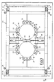
- la Fig. 3 est une vue schématique de dessus de l'installation de décrassage conforme à l'invention,
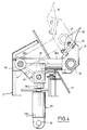
- la Fig. 4 est une vue de côté d'un râteau de raclage de la surface externe d'un plongeur de la cuve de traitement,
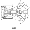
- la Fig. 5 est une vue de dessus de la Fig.4,
- la Fig. 6 est une vue de côté montrant les moyens d'actionnement d'un râteau de raclage,
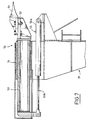
- la Fig.7 est une vue de côté des moyens de raclage de l'espace intermédiaire entre les plongeurs.
Claims (14)
- Installation de décrassage des plongeurs (12, 13) tubulaires en matériau réfractaire d'une cuve (1) de traitement sous vide de l'acier liquide comportant un bas de cuve supportant les plongeurs (12, 13) disposés verticalement et délimitant entre eux un espace intermédiaire (16), l'installation comprenant un bâti (21) déplaçable horizontalement et verticalement et comportant, à sa partie supérieure, des moyens (30) de raclage du bas vers le haut et simultané de la surface externe desdits plongeurs (12, 13), caractérisée en ce que les moyens de raclage sont formés, pour chacun desdits plongeurs (12, 13), par des râteaux (31) munis de doigts de décrassage (32), répartis selon une circonférence et déplaçables par des moyens (39, 41) d'actionnement entre une position escamotée dans laquelle les doigts (32) des râteaux (31) sont écartés de la surface externe des plongeurs (12, 13) et une position active dans laquelle les doigts (32) des râteaux (31) sont en contact avec la surface externe desdits plongeurs (12, 13) et en ce que chaque râteau (31) est formé par une barre transversale (33) comportant des supports (34) des doigts de décrassage (32) et par un manche longitudinal (35) s'étendant perpendiculairement à ladite barre (33), une première extrémité (35a) du manche (35) étant reliée à ladite barre (33) et une seconde extrémité (35b) de ce manche (35) étant solidaire d'un axe transversal (38) de pivotement dudit râteau (31), relié aux moyens (39, 41) d'actionnement.
- Installation selon la revendication 1, caractérisée en ce que le bâti (21) comporte, à sa partie supérieure, des moyens (50) de décrassage de l'espace intermédiaire (16) entre lesdits plongeurs (12, 13).
- Installation selon l'une des revendications 1 et 2, caractérisée en ce que le bâti (21) est équipé de moyen (22, 23) de déplacement horizontal pour amener ledit bâti (21) au-dessous desdits plongeurs (12, 13).
- Installation selon l'une des revendications 1 et 2, caractérisée en ce que le bâti (21) est équipé de moyens (24, 25, 26) de déplacement vertical pour amener les moyens (30) de raclage au niveau desdits plongeurs (12, 13).
- Installation selon la revendication 1 caractérisée en ce que chaque râteau (31) est déplaçable par coulissement longitudinal entre les deux positions.
- Installation selon revendication 1, caractérisée en ce que chaque râteau (31) est déplaçable par pivotement entre les deux positions.
- Installation selon la revendication 1, caractérisée en ce que les moyens d'actionnement du pivotement de chaque râteau (31) comprennent un vérin (39) par exemple hydraulique comportant un corps (39a) monté pivotant sur un axe (40) et une tige de commande (39b) dont l'extrémité libre est reliée à l'axe transversal (38) du manche (35) correspondant par au moins une biellette (41).
- Installation selon la revendication 1, caractérisée en ce que chaque doigt de décrassage (32) forme avec l'horizontale un angle compris entre 30 et 60°.
- Installation selon la revendication 2, caractérisée en ce que les moyens (50) de décrassage de l'espace intermédiaire (16) entre les plongeurs (12, 13) comportent au moins deux doigts de décrassage (51) opposés et déplaçables par des moyens (55) d'actionnement entre une position escamotée dans laquelle les doigts de décrassage (51) sont écartés de l'espace intermédiaire (16) et une position active dans laquelle les doigts de décrassage (51) sont positionnés dans ledit espace intermédiaire (16).
- Installation selon la revendication 9, caractérisée en ce que chaque doigt de décrassage (51) de l'espace intermédiaire (16) est monté sur un support (52) déplaçable par coulissement dans un fourreau (54) d'une tige (53) reliée aux moyens (55) d'actionnement.
- Installation selon l'une quelconque des revendications 1 à 10, caractérisée en ce que la position de chaque doigt de décrassage (32, 51) sur son support (34, 52) est réglable.
- Installation selon l'une quelconque des revendications 1 à 4, caractérisée en ce que le bâti (21) comporte, à sa partie supérieure, une trémie (17).
- Installation selon l'une quelconque des revendications 1 à 4, caractérisée en ce que le bâti (21) comporte un bac de récupération de la gangue d'encrassement enlevée des plongeurs (12, 13).
- Installation selon l'une quelconque des revendications 1 à 4, caractérisée en ce que le bâti (21) est équipé de lances de gunitage des surfaces externe et interne des plongeurs (12, 13).
Applications Claiming Priority (2)
| Application Number | Priority Date | Filing Date | Title |
|---|---|---|---|
| FR9614326A FR2756200B1 (fr) | 1996-11-22 | 1996-11-22 | Installation de decrassage des plongeurs d'une cuve de traitement sous vide de l'acier liquide |
| FR9614326 | 1996-11-22 |
Publications (2)
| Publication Number | Publication Date |
|---|---|
| EP0844310A1 EP0844310A1 (fr) | 1998-05-27 |
| EP0844310B1 true EP0844310B1 (fr) | 2001-10-10 |
Family
ID=9497930
Family Applications (1)
| Application Number | Title | Priority Date | Filing Date |
|---|---|---|---|
| EP97402772A Expired - Lifetime EP0844310B1 (fr) | 1996-11-22 | 1997-11-18 | Installation de décrassage des plongeurs d'une cuve de traitement sous vide de l'acier liquide |
Country Status (5)
| Country | Link |
|---|---|
| EP (1) | EP0844310B1 (fr) |
| AT (1) | ATE206768T1 (fr) |
| DE (1) | DE69707245T2 (fr) |
| ES (1) | ES2166963T3 (fr) |
| FR (1) | FR2756200B1 (fr) |
Families Citing this family (2)
| Publication number | Priority date | Publication date | Assignee | Title |
|---|---|---|---|---|
| DE20022375U1 (de) * | 2000-06-09 | 2001-08-09 | SMS Mevac GmbH, 45141 Essen | Rüsselreinigungseinrichtung für Vakuumentgasungsanlagen |
| DE102007040882A1 (de) * | 2007-08-29 | 2009-03-05 | Sms Mevac Gmbh | Reinigungsvorrichtung für Tauchrohre bzw. Rüssel von Vakuumentgasungsanlagen |
Family Cites Families (5)
| Publication number | Priority date | Publication date | Assignee | Title |
|---|---|---|---|---|
| JPS5819446A (ja) * | 1981-07-25 | 1983-02-04 | Nisshin Steel Co Ltd | Rh炉等におけるスラグ除去装置 |
| GB8331152D0 (en) * | 1983-11-22 | 1983-12-29 | Henderson & Co Ltd John M | Vessel nozzle cleaning apparatus |
| JPS62151260A (ja) * | 1985-12-25 | 1987-07-06 | Kobe Steel Ltd | 溶湯浸漬管の付着物除去装置 |
| JPH0632842B2 (ja) * | 1989-04-28 | 1994-05-02 | 黒崎窯業株式会社 | 溶湯処理装置における浸漬管の付着物除去装置 |
| JPH0645820B2 (ja) * | 1989-12-28 | 1994-06-15 | 黒崎窯業株式会社 | 真空脱ガス設備の溶鋼吸上管の除滓装置 |
-
1996
- 1996-11-22 FR FR9614326A patent/FR2756200B1/fr not_active Expired - Fee Related
-
1997
- 1997-11-18 ES ES97402772T patent/ES2166963T3/es not_active Expired - Lifetime
- 1997-11-18 DE DE69707245T patent/DE69707245T2/de not_active Expired - Fee Related
- 1997-11-18 AT AT97402772T patent/ATE206768T1/de not_active IP Right Cessation
- 1997-11-18 EP EP97402772A patent/EP0844310B1/fr not_active Expired - Lifetime
Also Published As
| Publication number | Publication date |
|---|---|
| DE69707245T2 (de) | 2002-06-27 |
| FR2756200B1 (fr) | 1999-04-02 |
| ES2166963T3 (es) | 2002-05-01 |
| FR2756200A1 (fr) | 1998-05-29 |
| EP0844310A1 (fr) | 1998-05-27 |
| ATE206768T1 (de) | 2001-10-15 |
| DE69707245D1 (de) | 2001-11-15 |
Similar Documents
| Publication | Publication Date | Title |
|---|---|---|
| FR2460027A1 (fr) | Procede de manutention des assemblages et crayons combustibles lors du rechargement d'un reacteur nucleaire | |
| CA1112404A (fr) | Installation de decrassage de poches de coulee | |
| FR2535835A1 (fr) | Four a arc basculant | |
| FR2711557A1 (fr) | Procédé et dispositif pour le nettoyage d'éléments solides. | |
| EP0838540A1 (fr) | Procédé de changement d'anodes usées de cuves d'électrolyse de l'aluminium et dispositif de captage des effluents gazeux permettant de le mettre en oeuvre | |
| EP0844310A1 (fr) | Installation de décrassage des plongeurs d'une cuve de traitement sous vide de l'acier liquide | |
| EP2029463B1 (fr) | Dispositif et procede pour le chargement de particules solides dans une enceinte | |
| EP0734458B1 (fr) | Dispositif de chargement pour alimenter en metaliquide un four electrique | |
| FR2561664A1 (fr) | Recipient metallurgique, en particulier convertisseur d'acierie echangeable | |
| EP0767843A1 (fr) | Procede et dispositif d'enfournement direct de metal liquide d'une poche dans un four electrique | |
| FR2504663A1 (fr) | Procede et appareil de chargement d'un four | |
| FR2462466A1 (fr) | Procede et dispositif pour le nettoyage interieur de conduites montantes des chambres de cokefaction d'un four de cokefaction et dispositif de nettoyage pour la mise en oeuvre de ce procede | |
| FR2516095A1 (fr) | Installation d'affinage equipee d'un dispositif de mesure de la temperature et/ou de prelevement d'echantillons d'un bain d'acier liquide | |
| FR2688627A1 (fr) | Appareil pour sectionner par cassure l'extremite etroite d'une ampoule de tube cathodique. | |
| EP0234140A1 (fr) | Dispositif de nettoyage des trous d'anodes utilisées dans l'industrie de l'aluminium | |
| EP0501173A1 (fr) | Procédé de traitement de scories d'aciérie, installation pour sa mise en oeuvre et scories obtenues par ce procédé | |
| FR2685653A1 (fr) | Dispositif de refection du revetement interieur d'un trou de coulee notamment d'un convertisseur d'acierie. | |
| FR2668026A1 (fr) | Appareil permettant la recolte et le traitement de matieres premieres, avantageusement vegetales sans transbordement. | |
| FR3032456B1 (fr) | Machine de service pour l'exploitation d'une installation de production d'aluminium | |
| FR2819212A1 (fr) | Engin automoteur pour la coupe ou le ramassage de rondins et leur fendage en buches de bois de chauffage | |
| EP3903057B1 (fr) | Four à longerons mobiles permettant de broyer et d'évacuer en continue la calamine | |
| BE864267R (fr) | Dispositif de decrassage d'une lance de soufflage d'un recipient d'elaboration de l'acier | |
| FR2674946A1 (fr) | Four electrique de production de metal. | |
| CH509846A (fr) | Installation pour la fusion et la coulée des métaux | |
| EP0562913A1 (fr) | Enceinte contenant plusieurs lits de matière solide séparés et déchargeable par gravité sans mélange de matière |
Legal Events
| Date | Code | Title | Description |
|---|---|---|---|
| PUAI | Public reference made under article 153(3) epc to a published international application that has entered the european phase |
Free format text: ORIGINAL CODE: 0009012 |
|
| AK | Designated contracting states |
Kind code of ref document: A1 Designated state(s): AT BE CH DE DK ES FR GB IT LI LU NL SE |
|
| AX | Request for extension of the european patent |
Free format text: AL;LT;LV;RO;SI |
|
| 17P | Request for examination filed |
Effective date: 19981029 |
|
| AKX | Designation fees paid |
Free format text: AT BE CH DE DK ES FR GB IT LI LU NL SE |
|
| RBV | Designated contracting states (corrected) |
Designated state(s): AT BE CH DE DK ES FR GB IT LI LU NL SE |
|
| 17Q | First examination report despatched |
Effective date: 19991105 |
|
| RTI1 | Title (correction) |
Free format text: INSTALLATION FOR DESKULLING THE NOZZLES OF A VACUUM TREATING VESSEL FOR STEEL MELTS |
|
| GRAG | Despatch of communication of intention to grant |
Free format text: ORIGINAL CODE: EPIDOS AGRA |
|
| GRAG | Despatch of communication of intention to grant |
Free format text: ORIGINAL CODE: EPIDOS AGRA |
|
| GRAH | Despatch of communication of intention to grant a patent |
Free format text: ORIGINAL CODE: EPIDOS IGRA |
|
| GRAH | Despatch of communication of intention to grant a patent |
Free format text: ORIGINAL CODE: EPIDOS IGRA |
|
| GRAA | (expected) grant |
Free format text: ORIGINAL CODE: 0009210 |
|
| AK | Designated contracting states |
Kind code of ref document: B1 Designated state(s): AT BE CH DE DK ES FR GB IT LI LU NL SE |
|
| PG25 | Lapsed in a contracting state [announced via postgrant information from national office to epo] |
Ref country code: NL Free format text: LAPSE BECAUSE OF FAILURE TO SUBMIT A TRANSLATION OF THE DESCRIPTION OR TO PAY THE FEE WITHIN THE PRESCRIBED TIME-LIMIT Effective date: 20011010 Ref country code: GB Free format text: LAPSE BECAUSE OF FAILURE TO SUBMIT A TRANSLATION OF THE DESCRIPTION OR TO PAY THE FEE WITHIN THE PRESCRIBED TIME-LIMIT Effective date: 20011010 Ref country code: AT Free format text: LAPSE BECAUSE OF FAILURE TO SUBMIT A TRANSLATION OF THE DESCRIPTION OR TO PAY THE FEE WITHIN THE PRESCRIBED TIME-LIMIT Effective date: 20011010 |
|
| REF | Corresponds to: |
Ref document number: 206768 Country of ref document: AT Date of ref document: 20011015 Kind code of ref document: T |
|
| REG | Reference to a national code |
Ref country code: CH Ref legal event code: EP |
|
| REF | Corresponds to: |
Ref document number: 69707245 Country of ref document: DE Date of ref document: 20011115 |
|
| PG25 | Lapsed in a contracting state [announced via postgrant information from national office to epo] |
Ref country code: SE Free format text: LAPSE BECAUSE OF FAILURE TO SUBMIT A TRANSLATION OF THE DESCRIPTION OR TO PAY THE FEE WITHIN THE PRESCRIBED TIME-LIMIT Effective date: 20020110 Ref country code: DK Free format text: LAPSE BECAUSE OF FAILURE TO SUBMIT A TRANSLATION OF THE DESCRIPTION OR TO PAY THE FEE WITHIN THE PRESCRIBED TIME-LIMIT Effective date: 20020110 |
|
| NLV1 | Nl: lapsed or annulled due to failure to fulfill the requirements of art. 29p and 29m of the patents act | ||
| GBV | Gb: ep patent (uk) treated as always having been void in accordance with gb section 77(7)/1977 [no translation filed] |
Effective date: 20011010 |
|
| REG | Reference to a national code |
Ref country code: ES Ref legal event code: FG2A Ref document number: 2166963 Country of ref document: ES Kind code of ref document: T3 |
|
| PLBE | No opposition filed within time limit |
Free format text: ORIGINAL CODE: 0009261 |
|
| STAA | Information on the status of an ep patent application or granted ep patent |
Free format text: STATUS: NO OPPOSITION FILED WITHIN TIME LIMIT |
|
| 26N | No opposition filed | ||
| PGFP | Annual fee paid to national office [announced via postgrant information from national office to epo] |
Ref country code: CH Payment date: 20061016 Year of fee payment: 10 |
|
| PGFP | Annual fee paid to national office [announced via postgrant information from national office to epo] |
Ref country code: DE Payment date: 20061108 Year of fee payment: 10 |
|
| PGFP | Annual fee paid to national office [announced via postgrant information from national office to epo] |
Ref country code: ES Payment date: 20061113 Year of fee payment: 10 |
|
| PGFP | Annual fee paid to national office [announced via postgrant information from national office to epo] |
Ref country code: LU Payment date: 20061114 Year of fee payment: 10 |
|
| PGFP | Annual fee paid to national office [announced via postgrant information from national office to epo] |
Ref country code: BE Payment date: 20061128 Year of fee payment: 10 |
|
| PGFP | Annual fee paid to national office [announced via postgrant information from national office to epo] |
Ref country code: IT Payment date: 20061130 Year of fee payment: 10 |
|
| BERE | Be: lapsed |
Owner name: *PROSERTEC Effective date: 20071130 |
|
| PG25 | Lapsed in a contracting state [announced via postgrant information from national office to epo] |
Ref country code: LI Free format text: LAPSE BECAUSE OF NON-PAYMENT OF DUE FEES Effective date: 20071130 Ref country code: CH Free format text: LAPSE BECAUSE OF NON-PAYMENT OF DUE FEES Effective date: 20071130 |
|
| REG | Reference to a national code |
Ref country code: CH Ref legal event code: PL |
|
| PG25 | Lapsed in a contracting state [announced via postgrant information from national office to epo] |
Ref country code: BE Free format text: LAPSE BECAUSE OF NON-PAYMENT OF DUE FEES Effective date: 20071130 |
|
| PG25 | Lapsed in a contracting state [announced via postgrant information from national office to epo] |
Ref country code: DE Free format text: LAPSE BECAUSE OF NON-PAYMENT OF DUE FEES Effective date: 20080603 |
|
| PGFP | Annual fee paid to national office [announced via postgrant information from national office to epo] |
Ref country code: FR Payment date: 20061013 Year of fee payment: 10 |
|
| REG | Reference to a national code |
Ref country code: FR Ref legal event code: ST Effective date: 20080930 |
|
| REG | Reference to a national code |
Ref country code: ES Ref legal event code: FD2A Effective date: 20071119 |
|
| PG25 | Lapsed in a contracting state [announced via postgrant information from national office to epo] |
Ref country code: FR Free format text: LAPSE BECAUSE OF NON-PAYMENT OF DUE FEES Effective date: 20071130 Ref country code: ES Free format text: LAPSE BECAUSE OF NON-PAYMENT OF DUE FEES Effective date: 20071119 |
|
| PG25 | Lapsed in a contracting state [announced via postgrant information from national office to epo] |
Ref country code: LU Free format text: LAPSE BECAUSE OF NON-PAYMENT OF DUE FEES Effective date: 20071118 Ref country code: IT Free format text: LAPSE BECAUSE OF NON-PAYMENT OF DUE FEES Effective date: 20071118 |