EP0844162A1 - Ultrasonic measuring device of internal faults of a rail - Google Patents
Ultrasonic measuring device of internal faults of a rail Download PDFInfo
- Publication number
- EP0844162A1 EP0844162A1 EP97107249A EP97107249A EP0844162A1 EP 0844162 A1 EP0844162 A1 EP 0844162A1 EP 97107249 A EP97107249 A EP 97107249A EP 97107249 A EP97107249 A EP 97107249A EP 0844162 A1 EP0844162 A1 EP 0844162A1
- Authority
- EP
- European Patent Office
- Prior art keywords
- rail
- fact
- strip
- rollers
- probe
- Prior art date
- Legal status (The legal status is an assumption and is not a legal conclusion. Google has not performed a legal analysis and makes no representation as to the accuracy of the status listed.)
- Granted
Links
Images

Classifications
-
- G—PHYSICS
- G01—MEASURING; TESTING
- G01N—INVESTIGATING OR ANALYSING MATERIALS BY DETERMINING THEIR CHEMICAL OR PHYSICAL PROPERTIES
- G01N29/00—Investigating or analysing materials by the use of ultrasonic, sonic or infrasonic waves; Visualisation of the interior of objects by transmitting ultrasonic or sonic waves through the object
- G01N29/22—Details, e.g. general constructional or apparatus details
- G01N29/28—Details, e.g. general constructional or apparatus details providing acoustic coupling, e.g. water
-
- B—PERFORMING OPERATIONS; TRANSPORTING
- B61—RAILWAYS
- B61K—AUXILIARY EQUIPMENT SPECIALLY ADAPTED FOR RAILWAYS, NOT OTHERWISE PROVIDED FOR
- B61K9/00—Railway vehicle profile gauges; Detecting or indicating overheating of components; Apparatus on locomotives or cars to indicate bad track sections; General design of track recording vehicles
- B61K9/08—Measuring installations for surveying permanent way
- B61K9/10—Measuring installations for surveying permanent way for detecting cracks in rails or welds thereof
-
- G—PHYSICS
- G01—MEASURING; TESTING
- G01N—INVESTIGATING OR ANALYSING MATERIALS BY DETERMINING THEIR CHEMICAL OR PHYSICAL PROPERTIES
- G01N2291/00—Indexing codes associated with group G01N29/00
- G01N2291/04—Wave modes and trajectories
- G01N2291/044—Internal reflections (echoes), e.g. on walls or defects
-
- G—PHYSICS
- G01—MEASURING; TESTING
- G01N—INVESTIGATING OR ANALYSING MATERIALS BY DETERMINING THEIR CHEMICAL OR PHYSICAL PROPERTIES
- G01N2291/00—Indexing codes associated with group G01N29/00
- G01N2291/26—Scanned objects
- G01N2291/262—Linear objects
- G01N2291/2623—Rails; Railroads
Definitions
- the present invention relates to a device for measurement or detection of internal rail faults of a railway track and more particularly a device to ultrasonic suitable for continuous work on rails.
- Devices for the analysis of a body using a ultrasound beam are well known and they are used for the detection and measurement of internal faults of rails of a railway track either in situ content or in workshop. According to this principle an ultrasound beam is emitted towards the rail from a probe placed on the upper surface of the rail, the energy is reflected by the rail and its internal faults are then detected and measured by appropriate electronic circuits.
- Licences US 4689995, US 4700574 and EP 0374395 describe measurement methods and devices for their implementation artwork.
- Measuring devices have been developed such as that described in US Patent 5,522,265 in which the probes are placed in housings of a skid and are mounted movable in height relative to this skate while by being applied against the surface of the rail by a determined force. This prevents bouncing of the probes and improves the sound contact between the probes and the rail. he as a result, the working speed can be increased.
- the present invention thus aims to achieve a device for detection and / or measurement by ultrasound of internal faults in rail tracks that can be driven at high speed along the channel to be measured and whose ultrasonic probes are protected shocks and roughness or irregularities of the surface of the rail head so as to extend significantly their reliability and their lifespan.
- Another object of the present invention is also to increase reliability and accuracy of detection and the measurement of internal faults in the auscultated rails.
- the ultrasonic detection and / or measurement device faults in a rail of a railroad track according to the invention is distinguished by the characteristics listed in claim 1.
- the drawing illustrates schematically and as a example an embodiment of the device according to the invention.
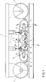
- Figure 1 is a schematic view of a carrier carriage intended to be mounted under a railway vehicle fitted with a detection and / or measurement device according to the invention.
- Figure 2 is an enlarged sectional view a probe holder support for the device.
- Figure 3 is a partial view at a larger scale of the framework of the device.
- Figure 4 is an enlarged detail showing the meshing of the belt on a roller.
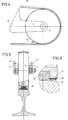
- Figure 5 is a partial section through larger scale along line B-B in Figure 1.
- Figure 6 is an enlarged detail of the figure 5.
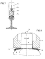
- Figure 7 is a section on a larger scale according to line A-A in Figure 1.
- Figure 8 is an enlarged detail of the figure 7.
- this device detection and / or ultrasonic measurement of faults of a railroad is to place between the probe (s) and the rail to examine a tape or belt to avoid direct contact between the rail and the probes.
- This strip can be made of synthetic material by polyamide example and have very smooth. This band is flexible so that it can fit the undulations of the rail.
- the strip is endless, closed on itself, passes between the probes and the rail then is wrapped around rollers and is subjected to the action of a tension roller.
- the part of the strip between the probes and the rail does not does not move relative to the rail, like a track, and the probes slide on the smooth surface of the bandaged.
- means are provided to ensure good sound contact between the probes and the tape as well between the strip and the rail, for example in the form of water films.
- the particular illustrated embodiment of the device for detecting and / or measuring internal faults of a rail using ultrasound includes a carrier trolley 1 running on the railway and intended to be connected to a rail vehicle (not shown), usually mounted under it, to be able to be dragged along the channel for detection or measurement.
- This carrier trolley 1 can also be connected to the chassis of the rail vehicle by lifting means to prevent this carriage does not roll on the track when walking high of the rail vehicle between two measurement sites or detection, for example.
- One or more of these carts carriers 1 can be placed under a railway vehicle, between its bogies, and each of these carrying carts 1 has flanged wheels 2 with the aid of which he rolls and is guided along the railway track.
- Each carrying trolley 1 carries at least one measure 3 for each line of rails in the track.
- These measuring carts 3 have a frame 4 connected by two cylinders 5 to the chassis of the carrying carriage 1 using which this measuring carriage 3 can either be lowered into position working low, or raised to the high rest position.
- the measuring carriage 3 has end rollers 6 crazy pivoted on the end of an arm 7 pivoted on the frame 4 and comprising a connecting rod 8 whose end is connected by a double-acting cylinder 9 to the frame 4.
- the cylinders 9 it is possible to modify the height of the corresponding roller 6 relative to the frame 4 of the measuring cart.
- Each of these rollers 6 ( Figures 5,6) has a part central with a groove receiving a bandage 10 in rubber for example intended to absorb transmitted shocks by the rail when this roller is resting on the rail.
- the lateral parts of the roller 6 are conical and can have teeth 11.
- the upper part of the frame 4 of the measuring carriage is fitted with a tensioner roller 12 that can be moved vertically relative to frame 4 for example using a jack (not shown).
- the periphery of this tensioner roller 12 is also toothed.
- the lower part of the frame 4 is connected using the double-acting cylinder 13 with measuring pads 14 having each two ultrasonic probes 15.
- Each measurement pad 14 (FIG. 2) carries two probes 15 sliding climbs along a vertical axis in the skid and subjected to the action of a single-acting cylinder 16 serving as shock absorber.
- This shoe 14 can be provided a water supply and recovery circuit to ensure the sound contact.
- this measuring carriage 3 is equipped with an endless belt 17 in smooth synthetic material such as polyacetane by example, and permeable to ultrasound, arranged below the surface lower of the probes and around the rollers 6.12.
- This endless band 17 is provided by gluing, welding or any other suitable means, in its two lateral parts, of toothed belts 18 incorporating cables or ropes 19 which prohibit any elongation of the strip.
- These belts notches 18 mesh with the teeth of the roller 12 and possibly rollers 6 and prevents any slipping of the strip 17 as well as its crossing.
- the notches of the belts 18 can be formed by lugs by example cooperating with corresponding roller bodies 12 and / or 6. Furthermore, these rollers may have smooth side parts.
- the carriage 3 is placed in the lower position, the strip 17 comes into contact with the rail.
- the measurement pads 14 are applied against the upper face of the strip 17 with a force determined by the cylinders 13 and the probes 15 are kept in contact with the surface of the smooth strip 17 by the damping cylinders 16.
- the strip 17 remains applied in contact with the rail and the measuring carriage 3 moving longitudinally there unrolls strip 17 like a track along the rail and the 15 probes slide on the smooth surface of the band 17 without rebounds, shocks or wear.
- the roller 6 located in the direction of travel is slightly lifted by its jack 9 and an injection device of water 20 creates a liquid film between the strip 17 and the rail to ensure good ultrasonic contact.
- the cart of measurement also includes injection means of water between the strip 17 and the measurement pads 14 for ensure good sound contact. These latter means may be deleted when the measurement pads 14 have an incorporated water injection system.
- rollers 6 it is possible to design the rollers 6 to be motorized by driving strip 17 which has the consequence of causing a displacement relative between the strip and the rail and decrease the speed of the relative movement between the probes and the bandaged. Such an arrangement can be advantageous for increase working speed while ensuring good ultrasonic contact between the probe and the rail through the band 17.
Abstract
Description
La présente invention concerne un dispositif pour la mesure ou la détection de défauts internes des rails d'une voie ferrée et plus particulièrement un dispositif à ultrasons adapté à travailler en continu sur les rails. Des dispositifs pour l'analyse d'un corps à l'aide d'un faisceau d'ultrasons sont bien connus et ils sont utilisés pour la détection et la mesure de défauts internes des rails d'une voie ferrée soit en contenu in situ, soit en atelier. Selon ce principe un faisceau d'ultrasons est émis en direction du rail à partir d'une sonde placée sur la surface supérieure du rail, l'énergie est réfléchie par le rail et ses défauts internes sont alors détectés et mesurés par des circuits électroniques appropriés. Les brevets US 4689995, US 4700574 et EP 0374395 décrivent des méthodes de mesure et des dispositifs pour leur mise en oeuvre.The present invention relates to a device for measurement or detection of internal rail faults of a railway track and more particularly a device to ultrasonic suitable for continuous work on rails. Devices for the analysis of a body using a ultrasound beam are well known and they are used for the detection and measurement of internal faults of rails of a railway track either in situ content or in workshop. According to this principle an ultrasound beam is emitted towards the rail from a probe placed on the upper surface of the rail, the energy is reflected by the rail and its internal faults are then detected and measured by appropriate electronic circuits. Licences US 4689995, US 4700574 and EP 0374395 describe measurement methods and devices for their implementation artwork.
Pour obtenir une mesure fiable il est essentiel d'assurer un bon contact acoustique entre la sonde et le rail. La position géométrique de la voie n'est jamais parfaite et un mauvais alignement des rails, des déformations ponctuelles des rails, ou les discontinuités de la voie dans les aiguilles par exemple, provoquent des sauts des sondes sur le rail et donc des pertes de contact acoustiques ce qui entraíne évidemment des perturbations dans la détection et la mesure des défauts des rails. Ces perturbations sont d'autant plus importantes que la vitesse de déplacement du véhicule portant les sondes est grande.To obtain a reliable measurement it is essential to ensure good acoustic contact between the probe and the rail. The geometric position of the track is never perfect and improper alignment of the rails, point deformations rails, or the discontinuities of the track in needles for example, cause probe jumps on the rail and therefore acoustic contact losses this which obviously causes disturbances in detection and measurement of rail faults. These disturbances are all the more important as the speed of movement of the vehicle carrying the probes is large.
Les chariots de mesure existants de ce type comportent jusqu'à une douzaine de sondes par file de rails pour permette une vérification complète de tous les défauts du rail. Ces sondes sont généralement portées par une poutre commune entraínée et guidée le long du rail à l'aide de moyens adéquats. Du fait de la masse et de la longueur de cette poutre il est extrêmement difficile, voire impossible, de garantir un contact sonde-rail parfait à tout moment, de sorte que ces dispositifs ne peuvent travailler qu'à des vitesses très limitées, inférieures à 20 Km/h par exemple.Existing measuring trolleys of this type include up to a dozen probes per line of rails to allow a complete check of all faults in the rail. These probes are generally carried by a beam town driven and guided along the rail using adequate means. Due to the mass and length of this beam is extremely difficult, if not impossible, to guarantee perfect probe-rail contact to all moment, so these devices can only work at very limited speeds, less than 20 km / h per example.
Des dispositifs de mesure ont été développés tels que celui décrit dans le brevet US 5522265 dans lequel les sondes sont placées dans des logements d'un patin et sont montées déplaçables en hauteur par rapport à ce patin tout en étant appliquées contre la surface du rail par une force déterminée. Ceci empêche les rebonds des sondes et améliore le contact sonore entre les sondes et le rail. Il en résulte que la vitesse de travail peut être augmentée.Measuring devices have been developed such as that described in US Patent 5,522,265 in which the probes are placed in housings of a skid and are mounted movable in height relative to this skate while by being applied against the surface of the rail by a determined force. This prevents bouncing of the probes and improves the sound contact between the probes and the rail. he as a result, the working speed can be increased.
Néanmoins avec de tels dispositifs les sondes sont toujours en contact direct avec le rail elles subissent donc une usure importante et peuvent être endommagées sérieusement par des bavures ou ondulations prononcées de la surface du rail. Ainsi, la durée de vie de telles sondes est très courte, il faut les changer fréquemment ce qui entraíne des coûts élevés et des arrêts de travail longs et fréquents.However with such devices the probes are always in direct contact with the rail they undergo therefore significant wear and can be seriously damaged by burrs or pronounced undulations of the rail surface. So the lifetime of such probes is very short, they must be changed frequently which results in high costs and long work stoppages and frequent.
La présente invention a ainsi pour but la réalisation d'un dispositif pour la détection et/ou la mesure par ultrasons des défauts internes des rails d'une voie ferrée qui puisse être entraíné à grande vitesse le long de la voie à mesurer et dont les sondes ultrasonores soient protégées des chocs et des aspérités ou irrégularités de la surface du champignon du rail de manière à prolonger de façon significative leur fiabilité et leur durée de vie. Un autre but de la présente invention est également d'augmenter la fiabilité et la précision de la détection et de la mesure des défauts internes des rails auscultés.The present invention thus aims to achieve a device for detection and / or measurement by ultrasound of internal faults in rail tracks that can be driven at high speed along the channel to be measured and whose ultrasonic probes are protected shocks and roughness or irregularities of the surface of the rail head so as to extend significantly their reliability and their lifespan. Another object of the present invention is also to increase reliability and accuracy of detection and the measurement of internal faults in the auscultated rails.
Le dispositif de détection et/ou de mesure par ultrasons des défauts d'un rail d'une voie ferrée selon l'invention se distingue par les caractéristiques énumérées à la revendication 1.The ultrasonic detection and / or measurement device faults in a rail of a railroad track according to the invention is distinguished by the characteristics listed in claim 1.
Le dessin illustre schématiquement et à titre d'exemple une forme d'exécution du dispositif selon l'invention.The drawing illustrates schematically and as a example an embodiment of the device according to the invention.
La figure 1 est une vue schématique d'un chariot porteur destiné à être monté sous un véhicule ferroviaire muni d'un dispositif de détection et/ou de mesure selon l'invention.Figure 1 is a schematic view of a carrier carriage intended to be mounted under a railway vehicle fitted with a detection and / or measurement device according to the invention.
La figure 2 est une vue en coupe à plus grande échelle d'un support porte-sonde du dispositif.Figure 2 is an enlarged sectional view a probe holder support for the device.
La figure 3 est une vue partielle à plus grande échelle du cadre du dispositif.Figure 3 is a partial view at a larger scale of the framework of the device.
La figure 4 est un détail à plus grande échelle montrant l'engrênement de la courroie sur un galet.Figure 4 is an enlarged detail showing the meshing of the belt on a roller.
La figure 5 est une coupe partielle à plus grande échelle suivant la ligne B-B de la figure 1.Figure 5 is a partial section through larger scale along line B-B in Figure 1.
La figure 6 est un détail à plus grande échelle de la figure 5. Figure 6 is an enlarged detail of the figure 5.
La figure 7 est une coupe à plus grande échelle suivant la ligne A-A de la figure 1.Figure 7 is a section on a larger scale according to line A-A in Figure 1.
La figure 8 est un détail à plus grande échelle de la figure 7.Figure 8 is an enlarged detail of the figure 7.
Comme on le verra dans la description détaillée qui suit la caractéristique nouvelle et originale de ce dispositif de détection et/ou de mesure par ultrasons des défauts d'un rail de chemin de fer consiste à placer entre la ou les sondes et le rail à ausculter une bande ou courroie pour éviter un contact direct entre le rail et les sondes. Cette bande peut être en matière synthétique par exemple en polyamide et présenter des surfaces très lisses. Cette bande est souple de manière à pouvoir épouser les ondulations du rail.As will be seen in the detailed description which follows the new and original feature of this device detection and / or ultrasonic measurement of faults of a railroad is to place between the probe (s) and the rail to examine a tape or belt to avoid direct contact between the rail and the probes. This strip can be made of synthetic material by polyamide example and have very smooth. This band is flexible so that it can fit the undulations of the rail.
Dans une forme d'exécution préférée, décrite ci-après, la bande est sans fin, fermée sur elle-même, passe entre les sondes et le rail puis est enroulée autour de galets et est soumise à l'action d'un rouleau tendeur. Dans une telle réalisation, lorsque le véhicule ferroviaire portant le dispositif de mesure se déplace le long de la voie, la partie de la bande située entre les sondes et le rail ne se déplace pas par rapport au rail, à l'instar d'une chenille, et les sondes glissent sur la surface lisse de la bande. Bien entendu des moyens sont prévus pour assurer un bon contact sonore entre les sondes et la bande ainsi qu'entre la bande et le rail, par exemple sous forme de films d'eau.In a preferred embodiment, described below, the strip is endless, closed on itself, passes between the probes and the rail then is wrapped around rollers and is subjected to the action of a tension roller. In such an embodiment, when the railway vehicle carrying the measuring device moves along the track, the part of the strip between the probes and the rail does not does not move relative to the rail, like a track, and the probes slide on the smooth surface of the bandaged. Of course, means are provided to ensure good sound contact between the probes and the tape as well between the strip and the rail, for example in the form of water films.
La forme d'exécution particulière illustrée du dispositif
de détection et/ou de mesure des défauts internes
d'un rail à l'aide d'ultrasons comporte un chariot porteur
1 roulant sur la voie ferrée et destiné à être relié a un
véhicule ferroviaire (non illustré), généralement monté
sous celui-ci, pour pouvoir être entraíné le long de la
voie pour la détection ou la mesure. Ce chariot porteur 1
peut en outre être relié au châssis du véhicule ferroviaire
par des moyens de relevage pour éviter que ce chariot
ne roule sur la voie lors de la marche haut-le-pied
du véhicule ferroviaire entre deux chantiers de mesure ou
de détection, par exemple. Un ou plusieurs de ces chariots
porteurs 1 peuvent être disposés sous un véhicule ferroviaire,
entre ses bogies, et chacun de ces chariots porteurs
1 comporte des roues à boudins 2 à l'aide desquelles
il roule et est guidé le long de la voie ferrée.The particular illustrated embodiment of the device
for detecting and / or measuring internal faults
of a rail using ultrasound includes a carrier trolley
1 running on the railway and intended to be connected to a
rail vehicle (not shown), usually mounted
under it, to be able to be dragged along the
channel for detection or measurement. This carrier trolley 1
can also be connected to the chassis of the rail vehicle
by lifting means to prevent this carriage
does not roll on the track when walking high
of the rail vehicle between two measurement sites or
detection, for example. One or more of these carts
carriers 1 can be placed under a railway vehicle,
between its bogies, and each of these carrying carts
1 has flanged
Chaque chariot porteur 1 porte au moins un chariot de
mesure 3 pour chaque file de rails de la voie ferrée. Ces
chariots de mesure 3 comportent un cadre 4 relié par deux
vérins 5 au châssis du chariot porteur 1 à l'aide desquels
ce chariot de mesure 3 peut être soit descendu en position
basse de travail, soit remonté en position haute de repos.Each carrying trolley 1 carries at least one
measure 3 for each line of rails in the track. These
measuring carts 3 have a
Le chariot de mesure 3 comporte des galets d'extrémités
6 pivotés fous sur l'extrémité d'un bras 7 pivoté sur
le cadre 4 et comportant une bielle 8 dont l'extrémité est
reliée par un vérin à double effet 9 au cadre 4. Ainsi, en
actionnant, les vérins 9 il est possible de modifier la
hauteur du galet 6 correspondant par rapport au cadre 4 du
chariot de mesure.The measuring carriage 3 has
Chacun de ces galets 6 (figures 5,6) comporte une partie
centrale munie d'une gorge recevant un bandage 10 en
caoutchouc par exemple destiné à amortir les chocs transmis
par le rail lorsque ce galet est en appui sur le rail.
Les parties latérales du galet 6 sont coniques et peuvent
être munies d'une denture 11.Each of these rollers 6 (Figures 5,6) has a part
central with a groove receiving a
La partie supérieure du cadre 4 du chariot de mesure
est munie d'un galet tendeur 12 déplaçable verticalement
par rapport au cadre 4 par exemple à l'aide d'un vérin
(non représenté). La périphérie de ce galet tendeur 12 est
également dentée.The upper part of the
La partie inférieure du cadre 4 est reliée à l'aide du
vérin à double effet 13 à des patins de mesure 14 présentant
chacun deux sondes ultrasonores 15.The lower part of the
Chaque patin de mesure 14 (figure 2) porte deux sondes
15 montées coulissantes suivant un axe vertical dans le
patin et soumis à l'action d'un vérin à simple effet 16
servant d'amortisseur de chocs. Ce patin 14 peut être muni
d'un circuit d'amenée et de récupération d'eau pour assurer
le contact sonore. Ces patins de mesure 14 ne seront
pas décrits en détails car leur construction et leur fonctionnement
fait l'objet des demandes de brevets CH
No 1003/94 et No 3843/94) et du brevet US 5522265.Each measurement pad 14 (FIG. 2) carries two
Pour éviter l'usure des sondes 15 et pour réduire
encore les chocs subis par ces sondes 15 dus aux inégalités
du rail et des abouts de rails ou joints le présent
chariot de mesure 3 est équipé d'une bande sans fin 17 en
matière synthétique lisse comme du polyacétane par
exemple, et perméable aux ultrasons, disposée sous la surface
inférieure des sondes et autour des galets 6,12.
Cette bande sans fin 17 est munie par collage, soudure ou
tout autre moyen adéquat, dans ses deux parties latérales,
de courroies crantées 18 incorporant des câbles ou filins
19 qui interdisent toute élongation de la bande. Ces courroies
crantées 18 engrènent avec la denture du galet 12 et
éventuellement des galets 6 et empêche tout glissement de
la bande 17 ainsi que sa mise en travers.To avoid wear of the
Il est évident que dans des variantes, les crans des
courroies 18 peuvent être constitués par des ergots par
exemple coopérant avec des organes correspondants des galets
12 et/ou 6. Par ailleurs, ces galets peuvent présenter
des parties latérales lisses.It is obvious that in variants, the notches of the
Pendant l'opération de mesure ou de détection le chariot
de mesure 3 est disposé en position basse, la bande
17 vient au contact du rail. Les patins de mesure 14 sont
appliqués contre la face supérieure de la bande 17 avec
une force déterminée par les vérins 13 et les sondes 15
sont maintenues au contact de la surface de la bande lisse
17 par les vérins amortisseurs 16.During the measurement or detection operation the carriage
3 is placed in the lower position, the
Lorsque le chariot porteur 1 est entraíné le long de
la voie, la bande 17 reste appliquée au contact du rail et
le chariot de mesure 3 se déplaçant longitudinalement il
déroule la bande 17 à l'instar d une chenille le long du
rail et les sondes 15 glissent sur la surface lisse de la
bande 17 sans rebonds, ni chocs, ni usure.When the carrier carriage 1 is driven along
the track, the
Le galet 6 situé dans le sens de la marche est légèrement
relevé par son vérin 9 et un dispositif d'injection
d'eau 20 créé un film liquide entre la bande 17 et le rail
pour assurer un bon contact ultrasonore. De même, le chariot
de mesure comporte encore des moyens d'injection
d'eau entre la bande 17 et les patins de mesure 14 pour
assurer un bon contact sonore. Ces derniers moyens peuvent
être supprimés lorsque les patins de mesure 14 comportent
un système d'injection d'eau incorporé.The
Les principaux avantages du dispositif de mesure
ultrasonore décrits sont les suivants :
Dans des variantes d'exécution, il est possible de
concevoir que les galets 6 soient motorisés en entraínant
la bande 17 ce qui a pour conséquence de provoquer un déplacement
relatif entre la bande et le rail et de diminuer
la vitesse du déplacement relatif entre les sondes et la
bande. Une telle disposition peut être avantageuse pour
augmenter la vitesse de travail tout en assurant un bon
contact ultrasonore entre la sonde et le rail à travers la
bande 17.In execution variants, it is possible to
design the
Claims (9)
Applications Claiming Priority (3)
| Application Number | Priority Date | Filing Date | Title |
|---|---|---|---|
| CH289896 | 1996-11-25 | ||
| CH02898/96A CH690851A5 (en) | 1996-11-25 | 1996-11-25 | Apparatus for measuring internal defects of a rail by ultrasound. |
| CH2898/96 | 1996-11-25 |
Publications (2)
| Publication Number | Publication Date |
|---|---|
| EP0844162A1 true EP0844162A1 (en) | 1998-05-27 |
| EP0844162B1 EP0844162B1 (en) | 2001-03-21 |
Family
ID=4244102
Family Applications (1)
| Application Number | Title | Priority Date | Filing Date |
|---|---|---|---|
| EP97107249A Expired - Lifetime EP0844162B1 (en) | 1996-11-25 | 1997-05-02 | Ultrasonic measuring device of internal faults of a rail |
Country Status (10)
| Country | Link |
|---|---|
| US (1) | US5804731A (en) |
| EP (1) | EP0844162B1 (en) |
| JP (1) | JP3768642B2 (en) |
| AT (1) | ATE199862T1 (en) |
| AU (1) | AU720996B2 (en) |
| CA (1) | CA2204173C (en) |
| CH (1) | CH690851A5 (en) |
| DE (1) | DE69704326T2 (en) |
| HK (1) | HK1010175A1 (en) |
| ZA (1) | ZA977595B (en) |
Cited By (1)
| Publication number | Priority date | Publication date | Assignee | Title |
|---|---|---|---|---|
| WO2009087385A3 (en) * | 2008-01-10 | 2009-10-15 | Sperry Rail (International) Limited | Sensor assembly |
Families Citing this family (38)
| Publication number | Priority date | Publication date | Assignee | Title |
|---|---|---|---|---|
| US6424150B2 (en) * | 1999-03-17 | 2002-07-23 | Southwest Research Institute | Magnetostrictive sensor rail inspection system |
| DE59905207D1 (en) * | 1998-07-22 | 2003-05-28 | Fraunhofer Ges Forschung | ULTRASOUND TEST EQUIPMENT |
| CA2396572C (en) * | 2000-01-05 | 2006-03-28 | Harsco Corporation | Automatic carriage alignment |
| US9733625B2 (en) | 2006-03-20 | 2017-08-15 | General Electric Company | Trip optimization system and method for a train |
| US10308265B2 (en) | 2006-03-20 | 2019-06-04 | Ge Global Sourcing Llc | Vehicle control system and method |
| US9950722B2 (en) | 2003-01-06 | 2018-04-24 | General Electric Company | System and method for vehicle control |
| DE10334902B3 (en) * | 2003-07-29 | 2004-12-09 | Nutronik Gmbh | Signal processing for non-destructive object testing involves storing digitized reflected ultrasonic signals and phase-locked addition of stored amplitude values with equal transition times |
| US9956974B2 (en) | 2004-07-23 | 2018-05-01 | General Electric Company | Vehicle consist configuration control |
| US7305885B2 (en) * | 2004-09-30 | 2007-12-11 | General Electric Company | Method and apparatus for phased array based ultrasonic evaluation of rail |
| NL1028325C2 (en) * | 2005-02-17 | 2006-08-21 | Sonimex B V | Method and device for detecting errors in a rail head. |
| US9828010B2 (en) | 2006-03-20 | 2017-11-28 | General Electric Company | System, method and computer software code for determining a mission plan for a powered system using signal aspect information |
| GB2436363B (en) * | 2006-03-24 | 2009-06-03 | Sperry Rail | System and method for the detection of faults in rails |
| ITVE20070044A1 (en) * | 2007-07-06 | 2009-01-07 | Tecnogamma S P A | METHOD AND EQUIPMENT FOR DYNAMIC INSPECTION NOT IN CONTACT WITH RAIL RAILS. |
| US8914171B2 (en) | 2012-11-21 | 2014-12-16 | General Electric Company | Route examining system and method |
| EP2270489B1 (en) * | 2009-07-02 | 2018-09-05 | HITACHI RAIL ITALY S.p.A. | Fault detection method and system |
| KR101196826B1 (en) | 2010-11-18 | 2012-11-01 | 한국철도기술연구원 | A automatic supersonic detection device for railroad rail |
| WO2014026091A2 (en) | 2012-08-10 | 2014-02-13 | General Electric Company | Route examining system and method |
| WO2014193610A1 (en) | 2013-05-30 | 2014-12-04 | Wabtec Holding Corp. | Broken rail detection system for communications-based train control |
| JP6288953B2 (en) * | 2013-06-03 | 2018-03-07 | 東京計器株式会社 | Rail inspection device |
| US9255913B2 (en) | 2013-07-31 | 2016-02-09 | General Electric Company | System and method for acoustically identifying damaged sections of a route |
| US9701326B2 (en) | 2014-09-12 | 2017-07-11 | Westinghouse Air Brake Technologies Corporation | Broken rail detection system for railway systems |
| US10349491B2 (en) | 2015-01-19 | 2019-07-09 | Tetra Tech, Inc. | Light emission power control apparatus and method |
| CA2892952C (en) | 2015-01-19 | 2019-10-15 | Tetra Tech, Inc. | Protective shroud |
| US9849895B2 (en) | 2015-01-19 | 2017-12-26 | Tetra Tech, Inc. | Sensor synchronization apparatus and method |
| US10362293B2 (en) | 2015-02-20 | 2019-07-23 | Tetra Tech, Inc. | 3D track assessment system and method |
| WO2017168795A1 (en) * | 2016-03-31 | 2017-10-05 | 株式会社Ihi | Nondestructive inspection method and coupling medium pressing jig |
| CN106248804A (en) * | 2016-09-26 | 2016-12-21 | 中车洛阳机车有限公司 | A kind of water supply installation of steel rail ultrasonic flaw detecting rail vehicle |
| CN108163010B (en) * | 2018-01-19 | 2019-06-04 | 西南交通大学 | A kind of modularization rail-defect detector car |
| US11377130B2 (en) | 2018-06-01 | 2022-07-05 | Tetra Tech, Inc. | Autonomous track assessment system |
| US10625760B2 (en) | 2018-06-01 | 2020-04-21 | Tetra Tech, Inc. | Apparatus and method for calculating wooden crosstie plate cut measurements and rail seat abrasion measurements based on rail head height |
| US10807623B2 (en) | 2018-06-01 | 2020-10-20 | Tetra Tech, Inc. | Apparatus and method for gathering data from sensors oriented at an oblique angle relative to a railway track |
| US10730538B2 (en) | 2018-06-01 | 2020-08-04 | Tetra Tech, Inc. | Apparatus and method for calculating plate cut and rail seat abrasion based on measurements only of rail head elevation and crosstie surface elevation |
| CN108819978A (en) * | 2018-06-22 | 2018-11-16 | 辽宁工程技术大学 | A kind of underground coal mine tramroad detection vehicle |
| CA3110960A1 (en) * | 2018-08-30 | 2020-03-05 | Voestalpine Signaling Usa Inc. | Railcar acoustic monitoring system and method of use |
| WO2020161691A1 (en) * | 2019-02-10 | 2020-08-13 | Scanmaster Systems (Irt) Ltd | Low maintentance rail monitoring probe |
| WO2020232443A1 (en) | 2019-05-16 | 2020-11-19 | Tetra Tech, Inc. | Autonomous track assessment system |
| CN113022606B (en) * | 2021-03-25 | 2022-04-26 | 神华新朔铁路有限责任公司 | Steel rail flaw detection trolley and steel rail flaw detection locomotive |
| CN113022641B (en) * | 2021-03-25 | 2022-04-29 | 神华新朔铁路有限责任公司 | Track flaw detection mechanism and track flaw detection vehicle |
Citations (3)
| Publication number | Priority date | Publication date | Assignee | Title |
|---|---|---|---|---|
| AU483896B2 (en) * | 1974-05-24 | 1975-11-27 | William Gieskieng Marion | Method and apparatus forthe detection of cracks and flaws in rail wheels, rails andthe like by sliding a prerecorded magnetic medium overthe test place |
| DE3424386A1 (en) * | 1984-07-03 | 1986-01-09 | Omnitest Gesellschaft für Qualitätssicherung mbH, 4690 Herne | Coupling and head-guiding foil for manual ultrasonic tests |
| EP0622629A1 (en) * | 1993-04-30 | 1994-11-02 | Westinghouse Electric Corporation | Ultrasonic booted head probe for rotor bore inspection |
Family Cites Families (11)
| Publication number | Priority date | Publication date | Assignee | Title |
|---|---|---|---|---|
| US3028751A (en) * | 1955-12-29 | 1962-04-10 | Ivan L Joy | Means for ultrasonic inspection of rail |
| US2992553A (en) * | 1957-04-24 | 1961-07-18 | Ivan L Joy | Coupling method and apparatus for ultrasonic testing of solid bodies |
| US3028753A (en) * | 1959-07-13 | 1962-04-10 | Ivan L Joy | Apparatus for wetting surfaces for ultrasonic testing |
| BE633687A (en) * | 1962-06-27 | |||
| US3768306A (en) * | 1971-12-20 | 1973-10-30 | C Stearns | Ultrasonic apparatus and method for analyzing defects in material |
| US3960005A (en) * | 1974-08-09 | 1976-06-01 | Canac Consultants Limited | Ultrasonic testing device for inspecting thermit rail welds |
| US4593569A (en) * | 1983-08-22 | 1986-06-10 | Joy Ivan L | Ultrasonic transducer unit to locate cracks in rail base |
| FR2561779B1 (en) * | 1984-03-23 | 1987-08-28 | Sncf | METHOD AND DEVICE FOR NON-DESTRUCTIVE TESTING OF A RAIL TRACK |
| CH665909A5 (en) * | 1985-05-15 | 1988-06-15 | Matix Ind Sa | METHOD AND DEVICE FOR ULTRASONIC DETECTION OF INTERNAL DEFECTS OF A RAILWAY RAIL LOCATED IN THE EDGE OF THE MUSHROOM OF THAT RAIL, USE OF THE DEVICE. |
| CH677973A5 (en) * | 1988-12-19 | 1991-07-15 | Speno International | |
| EP0676322B1 (en) * | 1994-04-06 | 1998-05-13 | Speno International S.A. | Ultrasonic measuring device of defaults of a railway rail |
-
1996
- 1996-11-25 CH CH02898/96A patent/CH690851A5/en not_active IP Right Cessation
-
1997
- 1997-04-23 US US08/839,179 patent/US5804731A/en not_active Expired - Lifetime
- 1997-04-30 CA CA002204173A patent/CA2204173C/en not_active Expired - Lifetime
- 1997-05-02 EP EP97107249A patent/EP0844162B1/en not_active Expired - Lifetime
- 1997-05-02 AT AT97107249T patent/ATE199862T1/en active
- 1997-05-02 DE DE69704326T patent/DE69704326T2/en not_active Expired - Lifetime
- 1997-05-20 JP JP12984497A patent/JP3768642B2/en not_active Expired - Lifetime
- 1997-05-21 AU AU23555/97A patent/AU720996B2/en not_active Expired
- 1997-08-25 ZA ZA9707595A patent/ZA977595B/en unknown
-
1998
- 1998-10-09 HK HK98111147A patent/HK1010175A1/en not_active IP Right Cessation
Patent Citations (3)
| Publication number | Priority date | Publication date | Assignee | Title |
|---|---|---|---|---|
| AU483896B2 (en) * | 1974-05-24 | 1975-11-27 | William Gieskieng Marion | Method and apparatus forthe detection of cracks and flaws in rail wheels, rails andthe like by sliding a prerecorded magnetic medium overthe test place |
| DE3424386A1 (en) * | 1984-07-03 | 1986-01-09 | Omnitest Gesellschaft für Qualitätssicherung mbH, 4690 Herne | Coupling and head-guiding foil for manual ultrasonic tests |
| EP0622629A1 (en) * | 1993-04-30 | 1994-11-02 | Westinghouse Electric Corporation | Ultrasonic booted head probe for rotor bore inspection |
Cited By (5)
| Publication number | Priority date | Publication date | Assignee | Title |
|---|---|---|---|---|
| WO2009087385A3 (en) * | 2008-01-10 | 2009-10-15 | Sperry Rail (International) Limited | Sensor assembly |
| GB2469009A (en) * | 2008-01-10 | 2010-09-29 | Sperry Rail | Sensor assembly |
| GB2469009B (en) * | 2008-01-10 | 2012-07-25 | Sperry Rail International Ltd | Sensor assembly |
| CN104608798A (en) * | 2008-01-10 | 2015-05-13 | 斯佩里铁轨(国际)有限公司 | Sensor assembly |
| US9254851B2 (en) | 2008-01-10 | 2016-02-09 | Sperry Rail International Limited | Sensor assembly |
Also Published As
| Publication number | Publication date |
|---|---|
| DE69704326D1 (en) | 2001-04-26 |
| JP3768642B2 (en) | 2006-04-19 |
| US5804731A (en) | 1998-09-08 |
| HK1010175A1 (en) | 1999-06-17 |
| EP0844162B1 (en) | 2001-03-21 |
| JPH10160713A (en) | 1998-06-19 |
| DE69704326T2 (en) | 2001-08-23 |
| ZA977595B (en) | 1998-05-25 |
| CH690851A5 (en) | 2001-02-15 |
| AU2355597A (en) | 1998-05-28 |
| ATE199862T1 (en) | 2001-04-15 |
| CA2204173A1 (en) | 1998-05-25 |
| CA2204173C (en) | 2006-06-13 |
| AU720996B2 (en) | 2000-06-22 |
Similar Documents
| Publication | Publication Date | Title |
|---|---|---|
| EP0844162B1 (en) | Ultrasonic measuring device of internal faults of a rail | |
| BE1007917A3 (en) | TRACK RAILWAY CONSTRUCTION MACHINE movable WORKING FOR A CONTINUOUS DAMAGE BALLAST BED OF A RAILWAY TRACK. | |
| EP0676322A1 (en) | Ultrasonic measuring device of defaults of a railway rail | |
| CA2960074C (en) | Funicular driven by a cable with two towing sections and method for controlling such a funicular | |
| EP0114284B1 (en) | Device for continuously measuring the shape of the transversal profile of the useful part of the head of at least one rail of a railway track | |
| FR2638147A1 (en) | WINDING MACHINE, IN PARTICULAR PAPER OR CARDBOARD | |
| EP3241785A1 (en) | Belt conveyor with a device for assessing the belt tension | |
| FR2476708A1 (en) | MOBILE ASSEMBLY FOR CLEANING THE RAILWAY BALLAST LAYER AND CLEANING METHOD USING SUCH AN ASSEMBLY | |
| CA2064966C (en) | Creping machine | |
| EP0849397A1 (en) | Device for the continuous finishing of the reprofiling of the head of a railway rail | |
| CH670667A5 (en) | Rail reshaping equipment for railway track - has chassis supported on wheels at one side and with endless grinding belt other side | |
| FR2935715A1 (en) | DEVICE FOR MAINTENANCE OF RAILS | |
| EP2905195A1 (en) | Railhead measuring device | |
| FR2517718A1 (en) | DEVICE FOR TRACKING SKI SLOPES | |
| EP0332489B1 (en) | Device for placing a railway vehicle on a wheel reconditioning lathe | |
| FR2780377A1 (en) | TRANSPORT VEHICLE TRAIN, OF THE TUNNELIER FOLLOWING TYPE | |
| EP1676721A1 (en) | Railway wheel and bogie of a railway vehicle comprising such wheels | |
| FR3001447A1 (en) | Movable belt conveyer for transporting e.g. sand, has transverse guide assembly including guide elements distributed longitudinally along longitudinal profile of assembly and limiting clearance of profile transversely | |
| CA1024824A (en) | Continuous variable speed control system for travelling railings | |
| FR2705327A1 (en) | Device enabling a guide carriage travelling on a conveyor or on a circuit of conveyors to negotiate the concave and convex portions of the said conveyors | |
| FR2519789A1 (en) | CAPSTAN DRIVE MECHANISM IN TAPE RECORDERS | |
| FR2766217A1 (en) | Grinding machine with abrasive band for reducing irregularities on railway tracks | |
| FR2490171A1 (en) | BOGIE PROVIDED WITH A CROSS-SECTIONAL BEAM FOR THE SUPPORT OF THE BODY OF A RAIL VEHICLE | |
| FR2602500A1 (en) | ROLLING BRIDGE | |
| CH689207A5 (en) | Travelling ultrasound fault detector for railway line internal faults |
Legal Events
| Date | Code | Title | Description |
|---|---|---|---|
| PUAI | Public reference made under article 153(3) epc to a published international application that has entered the european phase |
Free format text: ORIGINAL CODE: 0009012 |
|
| AK | Designated contracting states |
Kind code of ref document: A1 Designated state(s): AT BE CH DE FR GB IT LI NL SE |
|
| AX | Request for extension of the european patent |
Free format text: AL;LT;LV;RO;SI |
|
| 17P | Request for examination filed |
Effective date: 19980925 |
|
| AKX | Designation fees paid |
Free format text: AT BE CH DE FR GB IT LI NL SE |
|
| RBV | Designated contracting states (corrected) |
Designated state(s): AT BE CH DE FR GB IT LI NL SE |
|
| GRAG | Despatch of communication of intention to grant |
Free format text: ORIGINAL CODE: EPIDOS AGRA |
|
| GRAG | Despatch of communication of intention to grant |
Free format text: ORIGINAL CODE: EPIDOS AGRA |
|
| GRAH | Despatch of communication of intention to grant a patent |
Free format text: ORIGINAL CODE: EPIDOS IGRA |
|
| 17Q | First examination report despatched |
Effective date: 20000731 |
|
| RAP1 | Party data changed (applicant data changed or rights of an application transferred) |
Owner name: SPENO INTERNATIONAL SA |
|
| GRAH | Despatch of communication of intention to grant a patent |
Free format text: ORIGINAL CODE: EPIDOS IGRA |
|
| GRAA | (expected) grant |
Free format text: ORIGINAL CODE: 0009210 |
|
| AK | Designated contracting states |
Kind code of ref document: B1 Designated state(s): AT BE CH DE FR GB IT LI NL SE |
|
| REF | Corresponds to: |
Ref document number: 199862 Country of ref document: AT Date of ref document: 20010415 Kind code of ref document: T |
|
| ITF | It: translation for a ep patent filed |
Owner name: CON LOR S.R.L. |
|
| REG | Reference to a national code |
Ref country code: CH Ref legal event code: NV Representative=s name: MICHELI & CIE INGENIEURS-CONSEILS Ref country code: CH Ref legal event code: EP |
|
| REF | Corresponds to: |
Ref document number: 69704326 Country of ref document: DE Date of ref document: 20010426 |
|
| GBT | Gb: translation of ep patent filed (gb section 77(6)(a)/1977) |
Effective date: 20010405 |
|
| REG | Reference to a national code |
Ref country code: GB Ref legal event code: IF02 |
|
| PLBE | No opposition filed within time limit |
Free format text: ORIGINAL CODE: 0009261 |
|
| STAA | Information on the status of an ep patent application or granted ep patent |
Free format text: STATUS: NO OPPOSITION FILED WITHIN TIME LIMIT |
|
| 26N | No opposition filed | ||
| REG | Reference to a national code |
Ref country code: FR Ref legal event code: PLFP Year of fee payment: 20 |
|
| PGFP | Annual fee paid to national office [announced via postgrant information from national office to epo] |
Ref country code: NL Payment date: 20160519 Year of fee payment: 20 |
|
| PGFP | Annual fee paid to national office [announced via postgrant information from national office to epo] |
Ref country code: CH Payment date: 20160413 Year of fee payment: 20 Ref country code: DE Payment date: 20160520 Year of fee payment: 20 Ref country code: GB Payment date: 20160520 Year of fee payment: 20 |
|
| PGFP | Annual fee paid to national office [announced via postgrant information from national office to epo] |
Ref country code: IT Payment date: 20160524 Year of fee payment: 20 Ref country code: FR Payment date: 20160520 Year of fee payment: 20 Ref country code: SE Payment date: 20160519 Year of fee payment: 20 Ref country code: BE Payment date: 20160519 Year of fee payment: 20 Ref country code: AT Payment date: 20160520 Year of fee payment: 20 |
|
| REG | Reference to a national code |
Ref country code: DE Ref legal event code: R071 Ref document number: 69704326 Country of ref document: DE |
|
| REG | Reference to a national code |
Ref country code: NL Ref legal event code: MK Effective date: 20170501 |
|
| REG | Reference to a national code |
Ref country code: CH Ref legal event code: PL |
|
| REG | Reference to a national code |
Ref country code: GB Ref legal event code: PE20 Expiry date: 20170501 |
|
| REG | Reference to a national code |
Ref country code: AT Ref legal event code: MK07 Ref document number: 199862 Country of ref document: AT Kind code of ref document: T Effective date: 20170502 |
|
| REG | Reference to a national code |
Ref country code: SE Ref legal event code: EUG |
|
| PG25 | Lapsed in a contracting state [announced via postgrant information from national office to epo] |
Ref country code: GB Free format text: LAPSE BECAUSE OF EXPIRATION OF PROTECTION Effective date: 20170501 |