EP0844039B1 - Horizontal welding method and welding equipment - Google Patents
Horizontal welding method and welding equipment Download PDFInfo
- Publication number
- EP0844039B1 EP0844039B1 EP97920937A EP97920937A EP0844039B1 EP 0844039 B1 EP0844039 B1 EP 0844039B1 EP 97920937 A EP97920937 A EP 97920937A EP 97920937 A EP97920937 A EP 97920937A EP 0844039 B1 EP0844039 B1 EP 0844039B1
- Authority
- EP
- European Patent Office
- Prior art keywords
- welding
- molten pool
- current
- heat source
- wires
- Prior art date
- Legal status (The legal status is an assumption and is not a legal conclusion. Google has not performed a legal analysis and makes no representation as to the accuracy of the status listed.)
- Expired - Lifetime
Links
Images



Classifications
-
- B—PERFORMING OPERATIONS; TRANSPORTING
- B23—MACHINE TOOLS; METAL-WORKING NOT OTHERWISE PROVIDED FOR
- B23K—SOLDERING OR UNSOLDERING; WELDING; CLADDING OR PLATING BY SOLDERING OR WELDING; CUTTING BY APPLYING HEAT LOCALLY, e.g. FLAME CUTTING; WORKING BY LASER BEAM
- B23K15/00—Electron-beam welding or cutting
- B23K15/0046—Welding
-
- B—PERFORMING OPERATIONS; TRANSPORTING
- B23—MACHINE TOOLS; METAL-WORKING NOT OTHERWISE PROVIDED FOR
- B23K—SOLDERING OR UNSOLDERING; WELDING; CLADDING OR PLATING BY SOLDERING OR WELDING; CUTTING BY APPLYING HEAT LOCALLY, e.g. FLAME CUTTING; WORKING BY LASER BEAM
- B23K26/00—Working by laser beam, e.g. welding, cutting or boring
- B23K26/14—Working by laser beam, e.g. welding, cutting or boring using a fluid stream, e.g. a jet of gas, in conjunction with the laser beam; Nozzles therefor
- B23K26/1423—Working by laser beam, e.g. welding, cutting or boring using a fluid stream, e.g. a jet of gas, in conjunction with the laser beam; Nozzles therefor the flow carrying an electric current
-
- B—PERFORMING OPERATIONS; TRANSPORTING
- B23—MACHINE TOOLS; METAL-WORKING NOT OTHERWISE PROVIDED FOR
- B23K—SOLDERING OR UNSOLDERING; WELDING; CLADDING OR PLATING BY SOLDERING OR WELDING; CUTTING BY APPLYING HEAT LOCALLY, e.g. FLAME CUTTING; WORKING BY LASER BEAM
- B23K26/00—Working by laser beam, e.g. welding, cutting or boring
- B23K26/20—Bonding
- B23K26/21—Bonding by welding
- B23K26/24—Seam welding
-
- B—PERFORMING OPERATIONS; TRANSPORTING
- B23—MACHINE TOOLS; METAL-WORKING NOT OTHERWISE PROVIDED FOR
- B23K—SOLDERING OR UNSOLDERING; WELDING; CLADDING OR PLATING BY SOLDERING OR WELDING; CUTTING BY APPLYING HEAT LOCALLY, e.g. FLAME CUTTING; WORKING BY LASER BEAM
- B23K26/00—Working by laser beam, e.g. welding, cutting or boring
- B23K26/346—Working by laser beam, e.g. welding, cutting or boring in combination with welding or cutting covered by groups B23K5/00 - B23K25/00, e.g. in combination with resistance welding
- B23K26/348—Working by laser beam, e.g. welding, cutting or boring in combination with welding or cutting covered by groups B23K5/00 - B23K25/00, e.g. in combination with resistance welding in combination with arc heating, e.g. tungsten inert gas [TIG], metal inert gas [MIG] or plasma welding
-
- B—PERFORMING OPERATIONS; TRANSPORTING
- B23—MACHINE TOOLS; METAL-WORKING NOT OTHERWISE PROVIDED FOR
- B23K—SOLDERING OR UNSOLDERING; WELDING; CLADDING OR PLATING BY SOLDERING OR WELDING; CUTTING BY APPLYING HEAT LOCALLY, e.g. FLAME CUTTING; WORKING BY LASER BEAM
- B23K37/00—Auxiliary devices or processes, not specially adapted for a procedure covered by only one of the other main groups of this subclass
- B23K37/06—Auxiliary devices or processes, not specially adapted for a procedure covered by only one of the other main groups of this subclass for positioning the molten material, e.g. confining it to a desired area
-
- B—PERFORMING OPERATIONS; TRANSPORTING
- B23—MACHINE TOOLS; METAL-WORKING NOT OTHERWISE PROVIDED FOR
- B23K—SOLDERING OR UNSOLDERING; WELDING; CLADDING OR PLATING BY SOLDERING OR WELDING; CUTTING BY APPLYING HEAT LOCALLY, e.g. FLAME CUTTING; WORKING BY LASER BEAM
- B23K9/00—Arc welding or cutting
- B23K9/08—Arrangements or circuits for magnetic control of the arc
-
- B—PERFORMING OPERATIONS; TRANSPORTING
- B23—MACHINE TOOLS; METAL-WORKING NOT OTHERWISE PROVIDED FOR
- B23K—SOLDERING OR UNSOLDERING; WELDING; CLADDING OR PLATING BY SOLDERING OR WELDING; CUTTING BY APPLYING HEAT LOCALLY, e.g. FLAME CUTTING; WORKING BY LASER BEAM
- B23K9/00—Arc welding or cutting
- B23K9/16—Arc welding or cutting making use of shielding gas
- B23K9/167—Arc welding or cutting making use of shielding gas and of a non-consumable electrode
-
- B—PERFORMING OPERATIONS; TRANSPORTING
- B23—MACHINE TOOLS; METAL-WORKING NOT OTHERWISE PROVIDED FOR
- B23K—SOLDERING OR UNSOLDERING; WELDING; CLADDING OR PLATING BY SOLDERING OR WELDING; CUTTING BY APPLYING HEAT LOCALLY, e.g. FLAME CUTTING; WORKING BY LASER BEAM
- B23K9/00—Arc welding or cutting
- B23K9/16—Arc welding or cutting making use of shielding gas
- B23K9/167—Arc welding or cutting making use of shielding gas and of a non-consumable electrode
- B23K9/1675—Arc welding or cutting making use of shielding gas and of a non-consumable electrode making use of several electrodes
-
- B—PERFORMING OPERATIONS; TRANSPORTING
- B23—MACHINE TOOLS; METAL-WORKING NOT OTHERWISE PROVIDED FOR
- B23K—SOLDERING OR UNSOLDERING; WELDING; CLADDING OR PLATING BY SOLDERING OR WELDING; CUTTING BY APPLYING HEAT LOCALLY, e.g. FLAME CUTTING; WORKING BY LASER BEAM
- B23K9/00—Arc welding or cutting
- B23K9/16—Arc welding or cutting making use of shielding gas
- B23K9/173—Arc welding or cutting making use of shielding gas and of a consumable electrode
- B23K9/1735—Arc welding or cutting making use of shielding gas and of a consumable electrode making use of several electrodes
Definitions
- This invention concerns a method of welding in the horizontal position, in which the molten pool is liable to experience deformation under the influence of gravity, and a welding apparatus for that purpose. More specifically, it concerns a welding method in the horizontal position to be used in the production of large structures such as smokestacks, bridges, pressure vessels and the like, and a welding apparatus for that purpose. It also concerns an apparatus for performing the method.
- Welding has been an indispensable process in the manufacture of large steel structures such as smokestacks, bridges and pressure vessels. Because such large structures cannot easily be inverted during production, some portions must be welded in the horizontal position.
- welding in the overhead position refers to welding a joint from below with the axis of the weld approximately horizontal.
- Welding in the flat position refers to welding a joint from above with the axis of the weld approximately horizontal.
- Welding in the horizontal position refers to welding a joint from the side with the axis of the weld approximately horizontal.
- Welding in the vertical position refers to welding a joint with a vertical axis of the weld lengthwise along the vertical.
- welding in the horizontal position will refer to welds such that the angle of the parent material with respect to a horizontal surface is either approximately vertical or within the range of 45° to 90°; and the weld line is either approximately horizontal or its angle with respect to a horizontal surface is within the range of 0° to 45°.
- the present invention is also applicable in a range of welding positions which might be called intermediate between the common overhead, flat and horizontal positions.
- horizontal position in the wider meaning specified above.
- JP-A-63-119980 which represents the closest prior art, discloses a welding method which uses a coil to produce a magnetic force to push the molten welding pool up against the force of gravity.
- a preferred embodiment of the present invention is designed as follows. It concerns a method of welding in the horizontal position, in which a heat source such as an arc, a laser or an electron beam is used to melt the parent material and form a molten pool. Because of the position of the weld, gravity tends to cause the bead to deform.
- a heat source such as an arc, a laser or an electron beam
- a current is made to flow in the molten pool in approximately the same direction as the weld line, and a magnetic field is induced in the molten pool orthogonal to the direction of the current.
- the joint is welded while an upward Lorentz force (opposite the direction of gravity) is generated in the molten pool.
- the means by which a current is made to flow in the direction of the weld line in the molten pool comprise a plurality of auxiliary wires. These wires are inserted into the molten pool and a current is passed through them. The current, ideally a unidirectional current, is made to flow in the molten pool in the direction of the weld line.
- a welding apparatus which is advantageous to implement the welding method comprises: a heat source for welding comprising an arc, a laser or an electron beam; a plurality of auxiliary wires placed so as to face the molten pool formed by the heat source; a power supply for generating a current to run through the wires; and a magnetic field inducing means to induce a magnetic field in the molten pool which intersects the surface of the parent material.
- an apparatus can be provided to pass a portion of the welding current into the auxiliary wires.
- auxiliary wires 5a and 5b are used. As is shown in Figure 1, the minus and plus sides of power supply 2 are connected to the respective wires. In addition to this, or instead of power supply 2, a portion of the welding current can be passed to auxiliary wire 5b, as shown in Figure 2.
- a current is conducted between auxiliary wires 5a and 5b, a unidirectional current A is created in molten pool 12.
- a Lorentz force 11 is activated in the direction which allows it to support the molten pool. This prevents the weld bead from sagging.
- auxiliary wires 5a and 5b When a current is conducted through auxiliary wires 5a and 5b, these wires are heated by the Joule effect, and their deposition rate is enhanced.
- the surface area of the wires which can absorb the radiant heat of the arc will be larger. Thus the melting capability of the wires will increase.
- the TIG hot-wire welding method is similar to the method according to this invention.
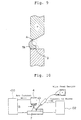
- heating power supply 102 which passes a current into consumable wire 101, is separate from TIG arc power supply 100.
- Current is supplied to consumable wire 101 from a point approximately 10 cm away from parent material 7, and the resistance heating heats wire 101. Since wire 101 is sent to the molten pool in a half-melted state, the deposition rate is increased by up to three times that of the usual method.
- the TIG hot-wire welding method and that according to the present embodiment have in common that they both involve supplying current to a consumable wire.
- the object of the former method is to heat the wire by resistance and send it to the molten pool in a half-melted state.
- That of the present embodiment is to pass a current through multiple melting wires in the direction of the weld line, and so induce a magnetic field in the molten pool 12 which is roughly orthogonal to the current. In this way a Lorentz force 11 will be activated in an upward direction in the molten pool 12.
- the former uses a single consumable wire
- the present embodiment uses two auxiliary wires, 5a and 5b, to pass a current in molten pool 12 in the direction of the weld line.
- Auxiliary wires 5a and 5b need not be consumable wires.
- an apparatus may be provided, as shown in Figure 7, which concentrates the heat source and applies a magnetic field.
- the present invention is particularly advantageously applied when the weld line is approximately horizontal and the surface of the parent material is approximately vertical.
- the effects of this invention are readily achieved throughout the range of horizontal position welding defined above, so long as a Lorentz force is generated in an upward direction (against the force of gravity) in the molten pool while the joint is welded.
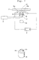
- Figure 1 shows the circuit connections in a welding apparatus in the horizontal position which is a first preferred embodiment of this invention.
- Figure 2 shows the circuit connections in a welding apparatus in the horizontal position which is a second preferred embodiment of this invention.
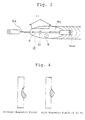
- Figure 3 is a drawing to illustrate how the molten metal is supported in a method of welding in the horizontal position according to an embodiment of this invention.
- Figure 4 shows cross sections of the bead in horizontal position welding.
- A shows the appearance of the bead without the application of a magnetic field.
- B is a cross section of a bead produced by an embodiment of this invention.
- Figure 5 shows the circuit connections in a welding apparatus in the horizontal position which is a third preferred embodiment of this invention.
- Figure 6 shows the circuit connections in a welding apparatus in the horizontal position which is a fourth preferred embodiment of this invention.
- FIG. 7 shows the circuit connections in a welding apparatus in the horizontal position which is a fifth preferred embodiment of this invention.
- (A) is an enlarged perspective drawing of the magnetic coil.
- Figure 8 shows the circuit connections in a welding apparatus in the horizontal position which is a sixth preferred embodiment of this invention.
- Figure 9 is a cross section of the welding area when the prior art welding method is used.
- Figure 10 shows an apparatus employing the TIG hot-wire welding method, a method belonging to the prior art.
- FIGs 1, 3 and 4 show a first preferred embodiment of this invention.
- This method, and the apparatus to make use of it, are used in TIG welding in the horizontal position. It employs an arc for heat source 10 and a nonconsumable electrode (a tungsten electrode) for electrode 13.
- a tungsten electrode a tungsten electrode
- 1 is the welding power supply.
- a TIG welding power supply with DC constant current characteristics is used.
- An arc (the heat source) is generated between electrode 13, which protrudes from welding torch 4, and parent material 7. The heat of the arc melts the parent material.
- auxiliary (melting) wires 5a and 5b are placed on molten pool 12 on either side of arc heat source 10.
- the wires 5a and 5b are connected, respectively, to the minus and plus sides of power supply 2. In this way a current is made to flow horizontally parallel to the weld line.
- the power supply 2 supplies a direct current and generates a constant electric field.
- a current splitting device 8 shown in Figure 2 can be used to pass a portion of the welding current to wire 5b.
- Current splitting device 8 may comprise two variable resistors so that the current supplied to auxiliary wire 5b may be varied.
- the welding torch 4 is surrounded by magnetic coil 6, which is connected to power supply 3.
- Magnetic field 9 can be induced in the direction which appears to be upward in Figure 1 (horizontally and orthogonal to the weld line).
- auxiliary wires 5a and 5b When a current is passed through auxiliary wires 5a and 5b, they are heated by the Joule effect just as in TIG hot-wire welding methods belonging to the prior art, and their deposition rate increases.
- the present invention makes use of multiple wires, 5a and 5b, so there is a greater surface area of these wires to absorb the radiant heat of arc heat source 10. As a result, the melting capacity of wires 5a and 5b is increased.
- the effect of this embodiment is verified from the shape of the bead obtained in a bead-on-plate welding test.
- the conditions of welding are a welding current of DC:500 A and a current to the wires of DC:120 A.
- the deposition rate of wires 5a and 5b is 100 g/min.
- the welding speed is 50 cm/min.
- the strength of the magnetic field 9 applied to molten pool 12 can be varied.
- the magnetic density is varied by changing the strength of the current from power supply 3 to magnetic coil 6, which is wound around TIG welding torch 4 as shown in Figure 1. Varying this current during welding will cause the magnetic flux density to vary.
- Figure 4 shows two cross sections of the welding location. In the one on the left, no magnetic field is applied. In the one on the right, a field with a magnetic flux density of 0.01 T (tesla) is applied. (The current from power supply 3 which induces the field is DC. The welding is done in a bead-on-plate test.) If we compare the two, we see clearly that the welding method according to this invention produces a bead which is buoyed up against the force of gravity.
- FIG. 2 illustrates the circuit connections in a welding apparatus in the horizontal position which is a second preferred embodiment of this invention.
- current splitting device 8 is placed in a location where the currents from power supplies 1 and 2 are confluent. A portion of the welding current supplied to parent material 7 is split off and supplied to auxiliary wire 5b.
- Current splitting device 8 comprises two variable resistors so that the current supplied to auxiliary wire 5b may be varied.
- FIG. 5 illustrates the circuit connections in a welding apparatus in the horizontal position which is a third preferred embodiment of this invention.
- Auxiliary wires 5a and 5b are on either side of arc heat source 10, but in this embodiment four wires are used, two on each side.
- one pair of auxiliary wires 5a and 5b is above heat source 10 and one pair is below it, parallel to the first pair, with the result that two unidirectional currents A are made to flow.
- This configuration achieves the same result as the first embodiment, except that the unidirectional current A is distributed over a larger area. This causes an upward Lorentz force to operate throughout molten pool 12 to produce a bead with a flat, smooth surface.
- FIG 6 illustrates the circuit connections in a welding apparatus in the horizontal position which is a fourth preferred embodiment of this invention.
- an arc is used as the heat source.
- Consumable electrode 14 is used to generate the arc instead of the non-consumable electrode in Figure 1. This configuration achieves the same effect as the first embodiment.
- Figure 7 illustrates the circuit connections in a welding apparatus in the horizontal position using a laser as the heat source.
- a laser as the heat source.
- a YAG or CO 2 laser is used as the heat source.
- the laser output is 4.5 Kw and the welding speed is 50 cm/min.
- the current which flows in molten pool 12 consists only of the current between auxiliary wires 5a and 5b; however, the same result is achieved as in the first embodiment.
- 16 in the drawing is a laser oscillator, and 15 is a condenser lens.
- Laser beam 17 is condensed onto the surface of the parent material.
- Magnetic coil 6 is wound around the condenser lens 15.
- Figure 8 illustrates the circuit connections in a welding apparatus in the horizontal position which uses an electron beam as the heat source.
- an electron beam is used as the heat source. If the voltage used to accelerate the beam is 60 kV, the beam current is 10 Ma, and the welding speed is 50 cm/min, the same result is achieved as in the first embodiment.
- 19 is an electron gun and 18 is a condenser lens. Electron beam 10' is condensed onto the surface of the parent material. Magnetic coil 6 is wound around the electron beam 10' in the vicinity of parent material 7.
- the current between auxiliary wires 5a and 5b and that flowing into the electromagnet are DC.
- the same effects could be achieved with AC currents by changing the superposition of the DC components as well as their duty factors and by controlling the phase relationship between the aforementioned two currents.
Landscapes
- Engineering & Computer Science (AREA)
- Physics & Mathematics (AREA)
- Mechanical Engineering (AREA)
- Plasma & Fusion (AREA)
- Optics & Photonics (AREA)
- Arc Welding Control (AREA)
- Arc Welding In General (AREA)
- Butt Welding And Welding Of Specific Article (AREA)
Description
When a current is conducted between
Claims (6)
- A method for welding in a horizontal position, wherein a parent material (7) is melted using a heat source (10, 10') to produce a molten pool (12) which is liable to deformation under the influence of gravity, further comprising steps of:inserting a plurality of auxiliary wires (5a-5d) into said molten pool (12),generating through said auxiliary wires (5a-5d) an electric current flow (A) in said molten pool (12) approximately along a direction of a weld line, andinducing a magnetic field (9) in said molten pool (12) approximately orthogonal to the direction of said electric current (A) to generate an upward Lorentz force (11) opposite a pull of gravity in said molten pool.
- A method according to claim 1, wherein said electric current flow (A) is a unidirectional current.
- A method according to claim 1 or 2, wherein said heat source (10, 10') is an arc, and a portion of a welding current for said arc is split off and provided to an auxiliary wire (5b).
- A welding apparatus for carrying out the method of any of claims 1 to 3, comprising:characterized bya heat source (10, 10') for welding which may be an arc,a laser (17) or an electron (10') beam;a magnetic field generating means (2, 5a-5d; 3, 6) to generate a magnetic field (9) in said molten pool (12) which intersects a surface of the parent material (7); anda plurality of auxiliary wires (5a-5d) provided so as to face the molten pool (12) formed by said heat source (10, 10') in the parent material (7);a power source (2) for generating an electric current through said plurality of auxiliary wires (5a-5d) and in said molten pool (12) approximately along a direction of a weld line.
- A welding apparatus according to claim 4, wherein said heat source is an arc, and a current splitting device (8) is provided to split off a portion of a welding current for said heat source and provides said portion to said auxiliary wires (5a-5d).
- A welding apparatus according to claim 4 or 5, further comprising a magnetic condensing means (61) to condense said magnetic field (9) onto said molten pool (12).
Applications Claiming Priority (4)
| Application Number | Priority Date | Filing Date | Title |
|---|---|---|---|
| JP14063896 | 1996-05-10 | ||
| JP140638/96 | 1996-05-10 | ||
| JP14063896 | 1996-05-10 | ||
| PCT/JP1997/001533 WO1997043073A1 (en) | 1996-05-10 | 1997-05-07 | Horizontal welding method and welding equipment |
Publications (3)
| Publication Number | Publication Date |
|---|---|
| EP0844039A1 EP0844039A1 (en) | 1998-05-27 |
| EP0844039A4 EP0844039A4 (en) | 1999-07-21 |
| EP0844039B1 true EP0844039B1 (en) | 2002-12-11 |
Family
ID=15273341
Family Applications (1)
| Application Number | Title | Priority Date | Filing Date |
|---|---|---|---|
| EP97920937A Expired - Lifetime EP0844039B1 (en) | 1996-05-10 | 1997-05-07 | Horizontal welding method and welding equipment |
Country Status (5)
| Country | Link |
|---|---|
| US (1) | US6023043A (en) |
| EP (1) | EP0844039B1 (en) |
| JP (1) | JP3219413B2 (en) |
| DE (1) | DE69717774T2 (en) |
| WO (1) | WO1997043073A1 (en) |
Families Citing this family (41)
| Publication number | Priority date | Publication date | Assignee | Title |
|---|---|---|---|---|
| US6364971B1 (en) * | 2000-01-20 | 2002-04-02 | Electric Power Research Institute | Apparatus and method of repairing turbine blades |
| US6378882B1 (en) * | 2001-02-01 | 2002-04-30 | John Devine | Human-powered exercise cycle |
| US6884959B2 (en) * | 2001-09-07 | 2005-04-26 | Electric Power Research Institute, Inc. | Controlled composition welding method |
| DE10225781B4 (en) * | 2002-06-10 | 2006-07-27 | Universität Stuttgart Institut für Strahlwerkzeuge | Method for treating, in particular for welding, a workpiece with a high energy beam |
| US6888090B2 (en) * | 2003-01-07 | 2005-05-03 | General Electric Company | Electron beam welding method |
| CN1883151B (en) * | 2003-09-15 | 2010-06-16 | 英特尔公司 | Multi-carrier transmitter, multi-carrier receiver and method for communicating multiple spatial signal streams |
| US7371988B2 (en) | 2004-10-22 | 2008-05-13 | Electric Power Research Institute, Inc. | Methods for extending the life of alloy steel welded joints by elimination and reduction of the HAZ |
| US7484651B2 (en) | 2004-10-22 | 2009-02-03 | Electric Power Research Institute, Inc. | Method to join or repair superalloy hot section turbine components using hot isostatic processing |
| CN1293982C (en) * | 2004-11-25 | 2007-01-10 | 上海交通大学 | Double-tungsten argon arc preheating re-melting welder |
| AT502419B1 (en) * | 2005-09-09 | 2007-08-15 | Fronius Int Gmbh | WELDING BURNER AND METHOD FOR PROCESS CONTROL OF A WELDING SYSTEM |
| US10086461B2 (en) | 2009-01-13 | 2018-10-02 | Lincoln Global, Inc. | Method and system to start and use combination filler wire feed and high intensity energy source for welding |
| US8653417B2 (en) * | 2009-01-13 | 2014-02-18 | Lincoln Global, Inc. | Method and system to start and use a combination filler wire feed and high intensity energy source |
| US9085041B2 (en) | 2009-01-13 | 2015-07-21 | Lincoln Global, Inc. | Method and system to start and use combination filler wire feed and high intensity energy source for welding |
| CN102152011B (en) * | 2011-01-24 | 2013-01-23 | 天津工业大学 | Method and device for stably forming all-position welding pool |
| CN102133679B (en) * | 2011-01-29 | 2013-03-06 | 北京工业大学 | Device and method for assisting gas metal arc welding by using externally applied magnetic fields |
| CN103042306B (en) * | 2011-10-12 | 2015-06-03 | 中国科学院力学研究所 | Method for measuring effects of gravity on laser welded joint welded seam shapes |
| US10201877B2 (en) | 2011-10-26 | 2019-02-12 | Titanova Inc | Puddle forming and shaping with primary and secondary lasers |
| US9862050B2 (en) * | 2012-04-03 | 2018-01-09 | Lincoln Global, Inc. | Auto steering in a weld joint |
| CN104428099B (en) * | 2012-08-14 | 2017-07-04 | 依赛彼公司 | Method and system for submerged arc welding |
| US20140263231A1 (en) * | 2013-03-15 | 2014-09-18 | Lincoln Global, Inc. | Tandem hot-wire systems |
| US10035211B2 (en) | 2013-03-15 | 2018-07-31 | Lincoln Global, Inc. | Tandem hot-wire systems |
| US10086465B2 (en) * | 2013-03-15 | 2018-10-02 | Lincoln Global, Inc. | Tandem hot-wire systems |
| US9498838B2 (en) | 2013-07-24 | 2016-11-22 | Lincoln Global, Inc. | System and method of controlling heat input in tandem hot-wire applications |
| CN103624371A (en) * | 2013-11-29 | 2014-03-12 | 天津工业大学 | Method for improving power output of all-position MAG (Metal Active Gas Arc) welding power supply |
| US10464168B2 (en) | 2014-01-24 | 2019-11-05 | Lincoln Global, Inc. | Method and system for additive manufacturing using high energy source and hot-wire |
| CN104057199A (en) * | 2014-06-30 | 2014-09-24 | 无锡市威海达机械制造有限公司 | Welding method of book page type metal structure |
| EP3034225B1 (en) * | 2014-12-17 | 2018-10-17 | Airbus Defence and Space GmbH | Method and apparatus for distortion control on additively manufactured parts using wire and magnetic pulses |
| US10040096B2 (en) | 2015-07-17 | 2018-08-07 | Caterpillar Inc. | Abrasion resistant material tandem welding |
| EP3500387A1 (en) * | 2016-08-18 | 2019-06-26 | Camarc LLC | Plasma arc welding system with at least two wire delivery mechanism, used with additive manufacturing |
| JP6722625B2 (en) * | 2017-08-24 | 2020-07-15 | 株式会社Ihi検査計測 | Hybrid welding method and hybrid welding apparatus |
| US11027362B2 (en) | 2017-12-19 | 2021-06-08 | Lincoln Global, Inc. | Systems and methods providing location feedback for additive manufacturing |
| DE102017223580A1 (en) | 2017-12-21 | 2019-06-27 | Robert Bosch Gmbh | Pressing device and corresponding method for pressing a metal foil on a support surface |
| CN108247226B (en) * | 2018-01-24 | 2020-09-01 | 北京工业大学 | Laser welding pool control method based on Lorentz force |
| CN109365965B (en) * | 2018-11-23 | 2021-01-05 | 哈尔滨工程大学 | Welding Droplet Transfer Control Equipment and Control Method Based on Ultrasonic Pulse Dual Tungsten Electrode Coordination |
| CN109967879A (en) * | 2019-03-30 | 2019-07-05 | 苏州欧米宁自动化科技有限公司 | A kind of pulse laser and arc welding compound welding equipment and welding procedure |
| CN111168194B (en) * | 2020-01-14 | 2022-06-28 | 佛山国防科技工业技术成果产业化应用推广中心 | Quadrupole magnetic field based method for controlling electric arc additive manufacturing and quadrupole magnetic field system |
| CN113414492B (en) * | 2021-07-22 | 2022-07-26 | 哈尔滨工业大学(威海) | Electromagnetic generating device and method for stabilizing laser deep melting welding keyhole |
| DE102021121146B4 (en) * | 2021-08-13 | 2023-07-13 | Bundesrepublik Deutschland, vertreten durch den Bundesminister für Wirtschaft und Energie, dieser vertreten durch den Präsidenten der Bundesanstalt für Materialforschung und –prüfung (BAM) | Use of an oscillating magnetic field as a pool support for arc welding processes, arc welding processes, apparatus for carrying out the same and self-propelled molten pool support |
| CN113409313B (en) * | 2021-08-18 | 2021-11-09 | 济宁联威车轮制造有限公司 | Wheel weld surface defect detection method based on computer vision |
| WO2024002488A1 (en) * | 2022-06-30 | 2024-01-04 | Bundesrepublik Deutschland, Vertreten Durch Den Bundesminister Für Wirtschaft Und Klimaschutz, Dieser Vertreten Durch Den Präsidenten Der Bundesanstalt Für Materialforschung Und -Prüfung, (Bam) | Electromagnetic melt pool support in direct energy deposition based additive manufacturing processes |
| CN116237643A (en) * | 2023-01-17 | 2023-06-09 | 国网浙江省电力有限公司湖州供电公司 | A method for preparing an insulating operating rod for ultra-high voltage transmission lines |
Family Cites Families (6)
| Publication number | Priority date | Publication date | Assignee | Title |
|---|---|---|---|---|
| US4190760A (en) * | 1976-05-14 | 1980-02-26 | Kobe Steel, Ltd. | Welding apparatus with shifting magnetic field |
| JPS61232080A (en) * | 1985-04-09 | 1986-10-16 | Nippon Kokan Kk <Nkk> | Laser welding method |
| JPS6238768A (en) * | 1985-08-14 | 1987-02-19 | Kobe Steel Ltd | Three o'clock tig arc welding method |
| JPS63108973A (en) * | 1986-10-23 | 1988-05-13 | Mitsubishi Heavy Ind Ltd | Magnetic stirring horizontal welding method |
| JPS63119980A (en) * | 1986-11-05 | 1988-05-24 | Mitsubishi Heavy Ind Ltd | Transverse attitude welding method |
| JP2778920B2 (en) * | 1994-11-11 | 1998-07-23 | 三菱重工業株式会社 | Lateral welding method and lateral welding device |
-
1997
- 1997-05-07 WO PCT/JP1997/001533 patent/WO1997043073A1/en not_active Ceased
- 1997-05-07 EP EP97920937A patent/EP0844039B1/en not_active Expired - Lifetime
- 1997-05-07 JP JP54071797A patent/JP3219413B2/en not_active Expired - Lifetime
- 1997-05-07 US US08/983,357 patent/US6023043A/en not_active Expired - Lifetime
- 1997-05-07 DE DE69717774T patent/DE69717774T2/en not_active Expired - Lifetime
Also Published As
| Publication number | Publication date |
|---|---|
| DE69717774T2 (en) | 2003-09-18 |
| EP0844039A1 (en) | 1998-05-27 |
| DE69717774D1 (en) | 2003-01-23 |
| JP3219413B2 (en) | 2001-10-15 |
| EP0844039A4 (en) | 1999-07-21 |
| US6023043A (en) | 2000-02-08 |
| WO1997043073A1 (en) | 1997-11-20 |
Similar Documents
| Publication | Publication Date | Title |
|---|---|---|
| US6023043A (en) | Method of welding in the horizontal position and welding apparatus therefor | |
| JPWO1997043073A1 (en) | Horizontal welding method and welding equipment | |
| EP0832710B1 (en) | Welding method in the overhead and vertical positions | |
| CN101421069B (en) | Metal cored electrode for open root pass welding | |
| US7875827B2 (en) | Laser brazing improvement with twinspot | |
| US9718147B2 (en) | Method and system to start and use combination filler wire feed and high intensity energy source for root pass welding of the inner diameter of clad pipe | |
| JP3200613U (en) | System for induction heating of consumables during the laser arc hybrid process | |
| US9095929B2 (en) | Dual fillet welding methods and systems | |
| Hori et al. | Development of hot wire TIG welding methods using pulsed current to heat filler wire–research on pulse heated hot wire TIG welding processes | |
| JPH11509477A (en) | Enhanced laser beam welding | |
| EP2596896B1 (en) | Welding system and process with a laser device, a GMAW device and a GTAW device | |
| JP2002018582A (en) | Hybrid arc / laser welding with control of earth contactor position | |
| EP1478827A1 (en) | Method and apparatus for increasing welding rates for high aspect ratio welds | |
| CN108994427B (en) | Control method of DC welding arc magnetic deflection blowing using external magnetic field expansion device | |
| CN112975072A (en) | Method and system for assisting aluminum alloy/steel dissimilar metal melting and brazing by using additional alternating magnetic field | |
| JP2778920B2 (en) | Lateral welding method and lateral welding device | |
| RU2688033C1 (en) | Multilayer electronic beam welding method | |
| JP3867164B2 (en) | Welding method | |
| JPH04157079A (en) | Laser beam welding method | |
| KR100340639B1 (en) | Control method of welding Arc using induction coil | |
| JPH04157078A (en) | Laser beam welding method | |
| CN120587598A (en) | A welding device with AC asymmetric magnetic field controlling arc swing in horizontal welding position and its use method | |
| JPS6199582A (en) | Tig welding method in hot wire switching | |
| JPS586778A (en) | Vertical welding method | |
| RU94011413A (en) | AUTOMATIC ELECTRIC ARC SPOT WELDING METHOD |
Legal Events
| Date | Code | Title | Description |
|---|---|---|---|
| PUAI | Public reference made under article 153(3) epc to a published international application that has entered the european phase |
Free format text: ORIGINAL CODE: 0009012 |
|
| 17P | Request for examination filed |
Effective date: 19980121 |
|
| AK | Designated contracting states |
Kind code of ref document: A1 Designated state(s): DE FR GB |
|
| A4 | Supplementary search report drawn up and despatched |
Effective date: 19990608 |
|
| AK | Designated contracting states |
Kind code of ref document: A4 Designated state(s): DE FR GB |
|
| 17Q | First examination report despatched |
Effective date: 20000904 |
|
| GRAG | Despatch of communication of intention to grant |
Free format text: ORIGINAL CODE: EPIDOS AGRA |
|
| GRAG | Despatch of communication of intention to grant |
Free format text: ORIGINAL CODE: EPIDOS AGRA |
|
| GRAG | Despatch of communication of intention to grant |
Free format text: ORIGINAL CODE: EPIDOS AGRA |
|
| GRAH | Despatch of communication of intention to grant a patent |
Free format text: ORIGINAL CODE: EPIDOS IGRA |
|
| GRAH | Despatch of communication of intention to grant a patent |
Free format text: ORIGINAL CODE: EPIDOS IGRA |
|
| GRAA | (expected) grant |
Free format text: ORIGINAL CODE: 0009210 |
|
| AK | Designated contracting states |
Kind code of ref document: B1 Designated state(s): DE FR GB |
|
| REG | Reference to a national code |
Ref country code: GB Ref legal event code: FG4D |
|
| REF | Corresponds to: |
Ref document number: 69717774 Country of ref document: DE Date of ref document: 20030123 |
|
| ET | Fr: translation filed | ||
| PLBE | No opposition filed within time limit |
Free format text: ORIGINAL CODE: 0009261 |
|
| STAA | Information on the status of an ep patent application or granted ep patent |
Free format text: STATUS: NO OPPOSITION FILED WITHIN TIME LIMIT |
|
| 26N | No opposition filed |
Effective date: 20030912 |
|
| PGFP | Annual fee paid to national office [announced via postgrant information from national office to epo] |
Ref country code: FR Payment date: 20110523 Year of fee payment: 15 |
|
| PGFP | Annual fee paid to national office [announced via postgrant information from national office to epo] |
Ref country code: GB Payment date: 20110504 Year of fee payment: 15 |
|
| PGFP | Annual fee paid to national office [announced via postgrant information from national office to epo] |
Ref country code: DE Payment date: 20110505 Year of fee payment: 15 |
|
| GBPC | Gb: european patent ceased through non-payment of renewal fee |
Effective date: 20120507 |
|
| REG | Reference to a national code |
Ref country code: FR Ref legal event code: ST Effective date: 20130131 |
|
| REG | Reference to a national code |
Ref country code: DE Ref legal event code: R119 Ref document number: 69717774 Country of ref document: DE Effective date: 20121201 |
|
| PG25 | Lapsed in a contracting state [announced via postgrant information from national office to epo] |
Ref country code: GB Free format text: LAPSE BECAUSE OF NON-PAYMENT OF DUE FEES Effective date: 20120507 Ref country code: FR Free format text: LAPSE BECAUSE OF NON-PAYMENT OF DUE FEES Effective date: 20120531 |
|
| PG25 | Lapsed in a contracting state [announced via postgrant information from national office to epo] |
Ref country code: DE Free format text: LAPSE BECAUSE OF NON-PAYMENT OF DUE FEES Effective date: 20121201 |