EP0843538B1 - Stent for expanding physiological vessels - Google Patents
Stent for expanding physiological vessels Download PDFInfo
- Publication number
- EP0843538B1 EP0843538B1 EP95939332A EP95939332A EP0843538B1 EP 0843538 B1 EP0843538 B1 EP 0843538B1 EP 95939332 A EP95939332 A EP 95939332A EP 95939332 A EP95939332 A EP 95939332A EP 0843538 B1 EP0843538 B1 EP 0843538B1
- Authority
- EP
- European Patent Office
- Prior art keywords
- fact
- elements
- sleeve according
- extensible
- sleeve
- Prior art date
- Legal status (The legal status is an assumption and is not a legal conclusion. Google has not performed a legal analysis and makes no representation as to the accuracy of the status listed.)
- Expired - Lifetime
Links
Images

Classifications
-
- A—HUMAN NECESSITIES
- A61—MEDICAL OR VETERINARY SCIENCE; HYGIENE
- A61F—FILTERS IMPLANTABLE INTO BLOOD VESSELS; PROSTHESES; DEVICES PROVIDING PATENCY TO, OR PREVENTING COLLAPSING OF, TUBULAR STRUCTURES OF THE BODY, e.g. STENTS; ORTHOPAEDIC, NURSING OR CONTRACEPTIVE DEVICES; FOMENTATION; TREATMENT OR PROTECTION OF EYES OR EARS; BANDAGES, DRESSINGS OR ABSORBENT PADS; FIRST-AID KITS
- A61F2/00—Filters implantable into blood vessels; Prostheses, i.e. artificial substitutes or replacements for parts of the body; Appliances for connecting them with the body; Devices providing patency to, or preventing collapsing of, tubular structures of the body, e.g. stents
- A61F2/82—Devices providing patency to, or preventing collapsing of, tubular structures of the body, e.g. stents
- A61F2/86—Stents in a form characterised by the wire-like elements; Stents in the form characterised by a net-like or mesh-like structure
- A61F2/90—Stents in a form characterised by the wire-like elements; Stents in the form characterised by a net-like or mesh-like structure characterised by a net-like or mesh-like structure
- A61F2/91—Stents in a form characterised by the wire-like elements; Stents in the form characterised by a net-like or mesh-like structure characterised by a net-like or mesh-like structure made from perforated sheet material or tubes, e.g. perforated by laser cuts or etched holes
- A61F2/915—Stents in a form characterised by the wire-like elements; Stents in the form characterised by a net-like or mesh-like structure characterised by a net-like or mesh-like structure made from perforated sheet material or tubes, e.g. perforated by laser cuts or etched holes with bands having a meander structure, adjacent bands being connected to each other
-
- A—HUMAN NECESSITIES
- A61—MEDICAL OR VETERINARY SCIENCE; HYGIENE
- A61F—FILTERS IMPLANTABLE INTO BLOOD VESSELS; PROSTHESES; DEVICES PROVIDING PATENCY TO, OR PREVENTING COLLAPSING OF, TUBULAR STRUCTURES OF THE BODY, e.g. STENTS; ORTHOPAEDIC, NURSING OR CONTRACEPTIVE DEVICES; FOMENTATION; TREATMENT OR PROTECTION OF EYES OR EARS; BANDAGES, DRESSINGS OR ABSORBENT PADS; FIRST-AID KITS
- A61F2/00—Filters implantable into blood vessels; Prostheses, i.e. artificial substitutes or replacements for parts of the body; Appliances for connecting them with the body; Devices providing patency to, or preventing collapsing of, tubular structures of the body, e.g. stents
- A61F2/82—Devices providing patency to, or preventing collapsing of, tubular structures of the body, e.g. stents
- A61F2/848—Devices providing patency to, or preventing collapsing of, tubular structures of the body, e.g. stents having means for fixation to the vessel wall, e.g. barbs
-
- A—HUMAN NECESSITIES
- A61—MEDICAL OR VETERINARY SCIENCE; HYGIENE
- A61F—FILTERS IMPLANTABLE INTO BLOOD VESSELS; PROSTHESES; DEVICES PROVIDING PATENCY TO, OR PREVENTING COLLAPSING OF, TUBULAR STRUCTURES OF THE BODY, e.g. STENTS; ORTHOPAEDIC, NURSING OR CONTRACEPTIVE DEVICES; FOMENTATION; TREATMENT OR PROTECTION OF EYES OR EARS; BANDAGES, DRESSINGS OR ABSORBENT PADS; FIRST-AID KITS
- A61F2/00—Filters implantable into blood vessels; Prostheses, i.e. artificial substitutes or replacements for parts of the body; Appliances for connecting them with the body; Devices providing patency to, or preventing collapsing of, tubular structures of the body, e.g. stents
- A61F2/95—Instruments specially adapted for placement or removal of stents or stent-grafts
- A61F2/958—Inflatable balloons for placing stents or stent-grafts
-
- A—HUMAN NECESSITIES
- A61—MEDICAL OR VETERINARY SCIENCE; HYGIENE
- A61F—FILTERS IMPLANTABLE INTO BLOOD VESSELS; PROSTHESES; DEVICES PROVIDING PATENCY TO, OR PREVENTING COLLAPSING OF, TUBULAR STRUCTURES OF THE BODY, e.g. STENTS; ORTHOPAEDIC, NURSING OR CONTRACEPTIVE DEVICES; FOMENTATION; TREATMENT OR PROTECTION OF EYES OR EARS; BANDAGES, DRESSINGS OR ABSORBENT PADS; FIRST-AID KITS
- A61F2/00—Filters implantable into blood vessels; Prostheses, i.e. artificial substitutes or replacements for parts of the body; Appliances for connecting them with the body; Devices providing patency to, or preventing collapsing of, tubular structures of the body, e.g. stents
- A61F2/82—Devices providing patency to, or preventing collapsing of, tubular structures of the body, e.g. stents
- A61F2002/825—Devices providing patency to, or preventing collapsing of, tubular structures of the body, e.g. stents having longitudinal struts
-
- A—HUMAN NECESSITIES
- A61—MEDICAL OR VETERINARY SCIENCE; HYGIENE
- A61F—FILTERS IMPLANTABLE INTO BLOOD VESSELS; PROSTHESES; DEVICES PROVIDING PATENCY TO, OR PREVENTING COLLAPSING OF, TUBULAR STRUCTURES OF THE BODY, e.g. STENTS; ORTHOPAEDIC, NURSING OR CONTRACEPTIVE DEVICES; FOMENTATION; TREATMENT OR PROTECTION OF EYES OR EARS; BANDAGES, DRESSINGS OR ABSORBENT PADS; FIRST-AID KITS
- A61F2/00—Filters implantable into blood vessels; Prostheses, i.e. artificial substitutes or replacements for parts of the body; Appliances for connecting them with the body; Devices providing patency to, or preventing collapsing of, tubular structures of the body, e.g. stents
- A61F2/82—Devices providing patency to, or preventing collapsing of, tubular structures of the body, e.g. stents
- A61F2002/826—Devices providing patency to, or preventing collapsing of, tubular structures of the body, e.g. stents more than one stent being applied sequentially
-
- A—HUMAN NECESSITIES
- A61—MEDICAL OR VETERINARY SCIENCE; HYGIENE
- A61F—FILTERS IMPLANTABLE INTO BLOOD VESSELS; PROSTHESES; DEVICES PROVIDING PATENCY TO, OR PREVENTING COLLAPSING OF, TUBULAR STRUCTURES OF THE BODY, e.g. STENTS; ORTHOPAEDIC, NURSING OR CONTRACEPTIVE DEVICES; FOMENTATION; TREATMENT OR PROTECTION OF EYES OR EARS; BANDAGES, DRESSINGS OR ABSORBENT PADS; FIRST-AID KITS
- A61F2/00—Filters implantable into blood vessels; Prostheses, i.e. artificial substitutes or replacements for parts of the body; Appliances for connecting them with the body; Devices providing patency to, or preventing collapsing of, tubular structures of the body, e.g. stents
- A61F2/82—Devices providing patency to, or preventing collapsing of, tubular structures of the body, e.g. stents
- A61F2002/828—Means for connecting a plurality of stents allowing flexibility of the whole structure
-
- A—HUMAN NECESSITIES
- A61—MEDICAL OR VETERINARY SCIENCE; HYGIENE
- A61F—FILTERS IMPLANTABLE INTO BLOOD VESSELS; PROSTHESES; DEVICES PROVIDING PATENCY TO, OR PREVENTING COLLAPSING OF, TUBULAR STRUCTURES OF THE BODY, e.g. STENTS; ORTHOPAEDIC, NURSING OR CONTRACEPTIVE DEVICES; FOMENTATION; TREATMENT OR PROTECTION OF EYES OR EARS; BANDAGES, DRESSINGS OR ABSORBENT PADS; FIRST-AID KITS
- A61F2/00—Filters implantable into blood vessels; Prostheses, i.e. artificial substitutes or replacements for parts of the body; Appliances for connecting them with the body; Devices providing patency to, or preventing collapsing of, tubular structures of the body, e.g. stents
- A61F2/82—Devices providing patency to, or preventing collapsing of, tubular structures of the body, e.g. stents
- A61F2/848—Devices providing patency to, or preventing collapsing of, tubular structures of the body, e.g. stents having means for fixation to the vessel wall, e.g. barbs
- A61F2002/8486—Devices providing patency to, or preventing collapsing of, tubular structures of the body, e.g. stents having means for fixation to the vessel wall, e.g. barbs provided on at least one of the ends
-
- A—HUMAN NECESSITIES
- A61—MEDICAL OR VETERINARY SCIENCE; HYGIENE
- A61F—FILTERS IMPLANTABLE INTO BLOOD VESSELS; PROSTHESES; DEVICES PROVIDING PATENCY TO, OR PREVENTING COLLAPSING OF, TUBULAR STRUCTURES OF THE BODY, e.g. STENTS; ORTHOPAEDIC, NURSING OR CONTRACEPTIVE DEVICES; FOMENTATION; TREATMENT OR PROTECTION OF EYES OR EARS; BANDAGES, DRESSINGS OR ABSORBENT PADS; FIRST-AID KITS
- A61F2/00—Filters implantable into blood vessels; Prostheses, i.e. artificial substitutes or replacements for parts of the body; Appliances for connecting them with the body; Devices providing patency to, or preventing collapsing of, tubular structures of the body, e.g. stents
- A61F2/82—Devices providing patency to, or preventing collapsing of, tubular structures of the body, e.g. stents
- A61F2/86—Stents in a form characterised by the wire-like elements; Stents in the form characterised by a net-like or mesh-like structure
- A61F2/90—Stents in a form characterised by the wire-like elements; Stents in the form characterised by a net-like or mesh-like structure characterised by a net-like or mesh-like structure
- A61F2/91—Stents in a form characterised by the wire-like elements; Stents in the form characterised by a net-like or mesh-like structure characterised by a net-like or mesh-like structure made from perforated sheet material or tubes, e.g. perforated by laser cuts or etched holes
- A61F2/915—Stents in a form characterised by the wire-like elements; Stents in the form characterised by a net-like or mesh-like structure characterised by a net-like or mesh-like structure made from perforated sheet material or tubes, e.g. perforated by laser cuts or etched holes with bands having a meander structure, adjacent bands being connected to each other
- A61F2002/9155—Adjacent bands being connected to each other
- A61F2002/91558—Adjacent bands being connected to each other connected peak to peak
-
- A—HUMAN NECESSITIES
- A61—MEDICAL OR VETERINARY SCIENCE; HYGIENE
- A61F—FILTERS IMPLANTABLE INTO BLOOD VESSELS; PROSTHESES; DEVICES PROVIDING PATENCY TO, OR PREVENTING COLLAPSING OF, TUBULAR STRUCTURES OF THE BODY, e.g. STENTS; ORTHOPAEDIC, NURSING OR CONTRACEPTIVE DEVICES; FOMENTATION; TREATMENT OR PROTECTION OF EYES OR EARS; BANDAGES, DRESSINGS OR ABSORBENT PADS; FIRST-AID KITS
- A61F2230/00—Geometry of prostheses classified in groups A61F2/00 - A61F2/26 or A61F2/82 or A61F9/00 or A61F11/00 or subgroups thereof
- A61F2230/0002—Two-dimensional shapes, e.g. cross-sections
- A61F2230/0004—Rounded shapes, e.g. with rounded corners
- A61F2230/0013—Horseshoe-shaped, e.g. crescent-shaped, C-shaped, U-shaped
-
- A—HUMAN NECESSITIES
- A61—MEDICAL OR VETERINARY SCIENCE; HYGIENE
- A61F—FILTERS IMPLANTABLE INTO BLOOD VESSELS; PROSTHESES; DEVICES PROVIDING PATENCY TO, OR PREVENTING COLLAPSING OF, TUBULAR STRUCTURES OF THE BODY, e.g. STENTS; ORTHOPAEDIC, NURSING OR CONTRACEPTIVE DEVICES; FOMENTATION; TREATMENT OR PROTECTION OF EYES OR EARS; BANDAGES, DRESSINGS OR ABSORBENT PADS; FIRST-AID KITS
- A61F2250/00—Special features of prostheses classified in groups A61F2/00 - A61F2/26 or A61F2/82 or A61F9/00 or A61F11/00 or subgroups thereof
- A61F2250/0058—Additional features; Implant or prostheses properties not otherwise provided for
- A61F2250/0096—Markers and sensors for detecting a position or changes of a position of an implant, e.g. RF sensors, ultrasound markers
- A61F2250/0098—Markers and sensors for detecting a position or changes of a position of an implant, e.g. RF sensors, ultrasound markers radio-opaque, e.g. radio-opaque markers
Definitions
- the subject of the present invention is a sleeve internal stretch for surgical use for dilation of physiological conduits as defined in the preamble to claim 1.
- a sleeve is known from the document EP-A-0 221 570 or from document EP-A-0 335 341.
- the European patent N ° EP 221,570 filed by Mr. Julio Palmaz, describes a prosthesis intraluminal expandable vascular system, comprising a thin-walled tubular member formed by a plurality of elongated elements intersecting one with the other, this tubular element having a diameter allowing it to pass inside the section passage of the receiving conduit, this diameter can be increased by the application, by the interior of the element tubular, of a force extending radially towards the outside, the diameter obtained being variable and depending on the magnitude of the force applied to the organ tubular, some of the elongated elements being deformed definitively by the force exerted radially towards the outside to bring the tubular element to its expanded diameter, whereby the tubular member can dilate the passage section of the duct and remain in this state.
- the prosthesis includes a plurality of closed circular units in the form of "zigzag” arranged so as to form a cylinder and each including an endless series of straight sections connected by "nodes". These circular units are made integral with each other by elements longitudinal peripheral connection arranged in staggered or diagonal, also in wire welded, some of these elements having "beards" anti-migration, projecting outwards.
- the outer wall of the prosthesis is covered with a net ensuring the tightness of the assembly.
- the installation is carried out by compressing the prosthesis to introduce it into a tube mounted at the end of a catheter, the elasticity of the material constituting its radial extension as soon as it is released.
- This device has a number disadvantages. Self-extension does not allow control the pressure it exerts on the internal face of the leads, and the anti-migratory "beards" in thread metal can injure or even puncture the wall of the latter. In addition the sealing net, placed outside the prosthesis also risks to be pierced by anti-migration "beards".
- Stretch sleeves such as those described above also carry the risk of bending a once implemented, which can jeopardize the success of intervention in a number of interventions.
- the device according to the present invention eliminates all of these drawbacks. Indeed, it allows obtain extensible elements having no risk of uncontrolled migration or bending, while requiring a reduced expansion force for its implementation place and exerting on the walls of the duct physiological a perfectly determined pressure.
- the device consists a tubular sheath 1 - or sleeve - formed of portion of hollow cylinder whose wall, made of semi-rigid malleable material, is cut so as to determining annular 2 and longitudinal 3 elements, 4 playing the role of "meshes” and arranged so as to allowing said sheath to extend radially under the effect of internal pressure and keeping fit thus obtained (Figure 2).
- the internal pressure is caused for example by means of an inflatable element 5 mounted at the end of a catheter 6 ( Figure 3) according to a known technique.
- the sleeve will preferably be produced by EDM from a metal block such as stainless steel or tantalum, or by etching a thin-walled tube. It will for example be constituted longitudinal elongated elements 3, 4 parallel to the axis of the sleeve, interconnected by annular elements 2 arranged in staggered rows thus forming meshes rectangular. Longitudinal elements not deformable 3 wide will be arranged alternately with longitudinal elements 4 thin and deformable, of so that the expansion of the sleeve does not change its initial length.
- the sleeve 1 may however present in the context of claim 1 any configuration allowing an extension adjustable according to the pressure applied.
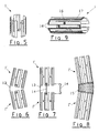
- the sleeve 1 For some applications, in particular for the treatment of vessels of the brain, the sleeve 1 must be very short. In this case it will consist of a single row of stitches (Figure 5).
- the sleeve 1 will advantageously be provided with integrated hooking means, directed radially towards the outside so as to sink into the inner wall of the vessel under the effect of element pressure inflatable 5, thus preventing all possibilities of moving the device.
- attachment means are constituted prominent elements 7 arranged at the ends and / or in the current part of the sheath 1. It can advantageously be prominent elements retractable 8 carried by blades 9 curved towards inside the sleeve, so that they normally set back from the element wall tubular and only come out of it when the inflatable element 5 for positioning is under pressure.
- the prominent elements 7, 8, will have a rounded shape so as not to risk injuring the wall of the physiological duct and can be performed by all appropriate means. They will preferably be trained by folding parts provided for this purpose of the wall of sheath 1, but can also be obtained by welding on said wall of added parts. These elements may possibly be removable, by example by breakage, so as to allow the surgeon to be able to decide, at the time of the operation, the number attachment means to be used without having to have for this a series of different sleeves.
- the means hooking consist of grooves 10 or annular undulations of the wall of the sheath 1, which can possibly be combined with elements prominences obtained by folding or welding ( Figure 4).
- a flexible tube 11 constituting a sheath waterproof may coat the internal or external face of the wall of the sleeve 1 so as to allow the use of the device for the surgical treatment of everything types of aneurysm. It will be made of polyester (type “Dacron” ®), in silicone fibers (“Teflon” ® type), polyurethane or ipolyethylene, woven or knitted, impregnated or not. This tube may be interrupted by places by gaps 12 to allow passage to secondary arteries or veins ( Figure 3).
- the sleeve 1 can consist of several 1 ', 1 "elements hinged together using one or more several longitudinal strips 13 integral with two contiguous elements 1 ', 1' '. Hooks 14, possibly removable, could be provided for block one or more joints if necessary ( Figures 6 and 7).
- the joints can also be obtained by means of a net 15 or a flexible film allowing the device to be placed in a portion bent of a vessel (Figure 8).
- the sleeves 1 made in this material will advantageously have points 16 or longitudinal 17 or annular 18 bands formed layers of a heavy metal such as tantalum, titanium or electrolytically deposited gold. These layers may have a thickness close to 0.1 mm.
- the device described is essentially to treat blood vessels with or more areas of narrowing or dilation (aneurysm) localized, but it may well be used for other physiological conduits, esophagus, intestines, ureters or urethra, common bile duct, pancreatic duct, etc.
Abstract
Description
La présente invention a pour objet un manchon extensible interne à usage chirurgical pour dilatation de conduits physiologiques comme défini dans le préambule de la revendication 1. Un tel manchon est connu du document EP-A-0 221 570 ou du document EP-A-0 335 341.The subject of the present invention is a sleeve internal stretch for surgical use for dilation of physiological conduits as defined in the preamble to claim 1. Such a sleeve is known from the document EP-A-0 221 570 or from document EP-A-0 335 341.
Elle est avant tout destinée à être mise en place dans une artère ou une veine pour empêcher localement son écrasement afin de permettre le passage du sang.It is primarily intended to be implemented place in an artery or vein to prevent locally its crushing in order to allow the passage of the blood.
Ce type de prothèse est en soi connu et utilisé depuis plusieurs années. Il en existe plusieurs modèles, fabriqués en faisant appel à des techniques variées.This type of prosthesis is known per se and used for several years. There are several models, made using techniques varied.
A titre d'exemple, le brevet européen N° EP 221 570, déposé par M. Julio Palmaz, décrit une prothèse vasculaire expansible intraluminaire, comprenant un organe de forme tubulaire à paroi mince formée par une pluralité d'éléments allongés s'intersectant l'un avec l'autre, cet élément tubulaire présentant un diamètre permettant de le faire passer à l'intérieur de la section de passage du conduit récepteur, ce diamètre pouvant être augmenté par l'application, par l'intérieur de l'élément tubulaire, d'une force s'étendant radialement vers l'extérieur, le diamètre obtenu étant variable et dépendant de l'ampleur de la force appliquée à l'organe tubulaire, certains des éléments allongés étant déformés de façon définitive par la force exercée radialement vers l'extérieur pour amener l'élément tubulaire à son diamètre expansé, ce par quoi l'élément tubulaire peut dilater la section de passage du conduit et demeurer dans cet état. For example, the European patent N ° EP 221,570, filed by Mr. Julio Palmaz, describes a prosthesis intraluminal expandable vascular system, comprising a thin-walled tubular member formed by a plurality of elongated elements intersecting one with the other, this tubular element having a diameter allowing it to pass inside the section passage of the receiving conduit, this diameter can be increased by the application, by the interior of the element tubular, of a force extending radially towards the outside, the diameter obtained being variable and depending on the magnitude of the force applied to the organ tubular, some of the elongated elements being deformed definitively by the force exerted radially towards the outside to bring the tubular element to its expanded diameter, whereby the tubular member can dilate the passage section of the duct and remain in this state.
A notre connaissance, aucun dispositif de ce type ne comporte de moyens satisfaisants assurant leur maintien en place, et il arrive trop fréquemment qu'ils soient entraínés sur une certaine distance par le flot sanguin, ce qui nécessite souvent une intervention chirurgicale. Le seul moyen de garantir à long terme le maintien en place de l'élément dilatateur, est d'exercer une force d'expansion élevée, ce qui entraíne le risque de provoquer la rupture du vaisseau traité, d'autant plus que ce vaisseau est dans la plupart des cas fragilisé par l'âge ou par la maladie.To our knowledge, no such device type does not have satisfactory means ensuring their holding in place, and too often they are driven a certain distance by the flow which often requires intervention surgical. The only way to guarantee the long term holding the dilator in place, is to exercise a high expansion force, which entails the risk to cause the rupture of the treated vessel, all the more that this vessel is in most cases weakened by age or disease.
Le brevet international N° WO 92 06 734 déposé par M. Ho Young SONG fait état d'une prothèse destinée à élargir le passage de conduits physiologiques, constituée d'une structure cylindrique auto-extensible radialement, réalisée en fil métallique soudé. La prothèse comprend une pluralité d'unités circulaires fermées en forme de "zigzag" agencées de façon à former un cylindre et incluant chacune une série sans fin de sections droites reliées par des "noeuds". Ces unités circulaires sont rendues solidaires les unes des autres par des éléments de liaison périphériques longitudinaux disposés en quinconce ou en diagonale, également en fil métallique soudé, certains de ces éléments comportant des "barbes" anti-migration, faisant saillie vers l'extérieur. La paroi externe de la prothèse est recouverte d'un filet assurant l'étanchéité de l'ensemble.International patent N ° WO 92 06 734 filed by Mr. Ho Young SONG mentions a prosthesis intended for widen the passage of physiological conduits, consisting a radially self-expanding cylindrical structure, made of welded wire. The prosthesis includes a plurality of closed circular units in the form of "zigzag" arranged so as to form a cylinder and each including an endless series of straight sections connected by "nodes". These circular units are made integral with each other by elements longitudinal peripheral connection arranged in staggered or diagonal, also in wire welded, some of these elements having "beards" anti-migration, projecting outwards. The outer wall of the prosthesis is covered with a net ensuring the tightness of the assembly.
La mise en place est effectuée en comprimant la prothèse pour l'introduire dans un tube monté à l'extrémité d'un cathéter, l'élasticité du matériau constitutif assurant son extension radiale dès qu'elle est libérée.The installation is carried out by compressing the prosthesis to introduce it into a tube mounted at the end of a catheter, the elasticity of the material constituting its radial extension as soon as it is released.
Ce dispositif présente un certain nombre d'inconvénients. L'auto-extension ne permet pas de contrôler la pression qu'il exerce sur la face interne du conduit, et les "barbes" anti-migratoires en fil métallique risquent de blesser ou même de perforer la paroi de ce dernier. En outre le filet d'étanchéité, disposé à l'extérieur de la prothèse risque également d'être percé par les "barbes" anti-migration.This device has a number disadvantages. Self-extension does not allow control the pressure it exerts on the internal face of the leads, and the anti-migratory "beards" in thread metal can injure or even puncture the wall of the latter. In addition the sealing net, placed outside the prosthesis also risks to be pierced by anti-migration "beards".
Les manchons extensibles tels que ceux décrits ci-dessus comportent en outre le risque de se cintrer une fois mis en place, ce qui peut compromettre le succès de l'intervention dans un certain nombre d'interventions.Stretch sleeves such as those described above also carry the risk of bending a once implemented, which can jeopardize the success of intervention in a number of interventions.
Le dispositif selon la présente invention supprime tous ces inconvénients. En effet, il permet d'obtenir des éléments extensibles ne présentant aucun risque de migration ou de cintrage non contrôlé, tout en nécessitant une force d'expansion réduite pour sa mise en place et en exerçant sur les parois du conduit physiologique une pression parfaitement déterminée.The device according to the present invention eliminates all of these drawbacks. Indeed, it allows obtain extensible elements having no risk of uncontrolled migration or bending, while requiring a reduced expansion force for its implementation place and exerting on the walls of the duct physiological a perfectly determined pressure.
Il est constitué comme défini dans la revendication 1, conformémment à une réalisation spécifique il est constitué d'un élément tubulaire
cylindrique métallique à paroi mince dont la paroi
comporte une série de perforations déterminant des
éléments annulaires et des éléments longitudinaux
alternativement déformables et non déformables
constituant un manchon malléable pouvant s'étendre
radialement sous l'effet d'une pression interne et garder
la forme ainsi obtenue, cet élément tubulaire comportant
de préférence des moyens d'accrochage non blessants
intégrés, dirigés vers l'extérieur et aptes à empêcher
toute migration du dispositif.It is constituted as defined in
Sur les dessins annexés, donnés à titre
d'exemples non limitatifs de formes de réalisation de
l'objet de l'invention:
Le dispositif, figures 1 à 9, est constitué
d'une gaine tubulaire 1 - ou manchon - formée d'une
portion de cylindre creux dont la paroi, réalisée en
matériau semi-rigide malléable, est découpée de manière à
déterminer des éléments annulaires 2 et longitudinaux 3,
4 jouant le rôle de "mailles" et agencés de manière à
permettre à ladite gaine de s'étendre radialement sous
l'effet d'une pression interne et de garder la forme
ainsi obtenue (figure 2). La pression interne est
provoquée par exemple au moyen d'un élément gonflable 5
monté à l'extrémité d'un cathéter 6 (figure 3) selon une
technique connue.The device, Figures 1 to 9, consists
a tubular sheath 1 - or sleeve - formed of
portion of hollow cylinder whose wall, made of
semi-rigid malleable material, is cut so as to
determining annular 2 and longitudinal 3 elements,
4 playing the role of "meshes" and arranged so as to
allowing said sheath to extend radially under
the effect of internal pressure and keeping fit
thus obtained (Figure 2). The internal pressure is
caused for example by means of an
Le manchon sera de préférence réalisé par
électro-érosion à partir d'un bloc de métal tel que
l'acier inoxydable ou le tantale, ou par gravure d'un
tube à paroi mince. Il sera par exemple constitué
d'éléments allongés longitudinaux 3, 4 parallèles à l'axe
du manchon, reliés entre eux par des éléments annulaires
2 disposés en quinconce formant ainsi des mailles
rectangulaires. Des éléments longitudinaux non
déformables 3 larges seront disposés alternativement avec
des éléments longitudinaux 4 fins et déformables, de
manière à ce que la dilatation du manchon ne modifie pas
sa longueur initiale. Le manchon 1 pourra toutefois
presenter dans le cadre de la revendication 1 toute configuration permettant une extension
ajustable en fonction de la pression appliquée.The sleeve will preferably be produced by
EDM from a metal block such as
stainless steel or tantalum, or by etching a
thin-walled tube. It will for example be constituted
longitudinal
Pour certaines applications, en particulier
pour le traitement des vaisseaux du cerveau, le manchon 1
doit être très court. Il sera dans ce cas constitué d'une
seule rangée de mailles (figure 5).For some applications, in particular
for the treatment of vessels of the brain, the
Le manchon 1 sera avantageusement pourvu de
moyens d'accrochage intégrés, dirigés radialements vers
l'extérieur de façon à s'enfoncer dans la paroi interne
du vaisseau sous l'effet de la pression de l'élément
gonflable 5, empêchant ainsi toutes possibilités de
déplacement du dispositif.The
Ces moyens d'accrochage sont constitués
d'éléments proéminents 7 disposés aux extrémités et/ou
dans la partie courante de la gaine 1. Il peut
avantageusement s'agir d'éléments proéminents
rétractables 8 portés par des lames 9 incurvées vers
l'intérieur du manchon, de telle manière qu'ils se
trouvent normalement en retrait de la paroi de l'élément
tubulaire et ne sortent de ce dernier que lorsque
l'élément gonflable 5 de mise en place est sous pression.These attachment means are constituted
Les éléments proéminents 7, 8, auront une
forme arrondie afin de ne pas risquer de blesser la paroi
du conduit physiologique et pourront être réalisés par
tous moyens appropriés. Ils seront de préférence formés
par pliage de parties prévues à cet effet de la paroi de
la gaine 1, mais pourront aussi bien être obtenus par
soudage sur ladite paroi de pièces rapportées. Ces
éléments pourront éventuellement être amovibles, par
exemple par cassure, de façon à permettre au chirurgien
de pouvoir décider, au moment de l'opération, du nombre
de moyens d'accrochage à utiliser sans avoir à disposer
pour cela d'une série de manchons différents.The
Dans une variante d'exécution, les moyens
d'accrochage sont constitués de cannelures 10 ou
ondulations annulaires de la paroi de la gaine 1, pouvant
éventuellement être combinées avec des éléments
proéminents obtenus par pliage ou soudage (figure 4).In an alternative embodiment, the means
hooking consist of
Un tube souple 11 constituant un fourreau
étanche pourra revêtir la face interne ou externe de la
paroi du manchon 1 de manière à permettre l'utilisation
du dispositif pour le traitement chirurgical de tout
types d'anévrisme. Il sera réalisé en polyester (type
"Dacron"®), en fibres silicones (type "Téflon"®), en
polyuréthanne ou ipolyéthylène, tissé ou tricoté,
imprégné ou non. Ce tube pourra être interrompu par
endroits par des lacunes 12 pour permettre le passage
vers des artères ou veines secondaires (figure 3).A
Le manchon 1 peut être constitué de plusieurs
éléments 1', 1" articulés entre eux grâce à une ou
plusieurs bandes longitudinales 13 solidaires de deux
éléments contigus 1', 1''. Des crochets 14,
éventuellement amovibles, pourront être prévus pour
bloquer une ou plusieurs articulations si nécessaire
(figures 6 et 7).The
Les articulations peuvent également être obtenues au moyen d'un filet 15 ou un film souple permettant au dispositif d'être placé dans une portion courbée d'un vaisseau (figure 8).The joints can also be obtained by means of a net 15 or a flexible film allowing the device to be placed in a portion bent of a vessel (Figure 8).
L'acier inoxydable est peu visible aux rayons
X. Pour y remédier, les manchons 1 réalisés dans ce
matériau comporteront avantageusement des points 16 ou
des bandes longitudinales 17 ou annulaires 18 constituées
de couches d'un métal lourd tel que le tantale, le titane
ou l'or déposé par voie électrolytique. Ces couches
pourront avoir une épaisseur voisine de 0,1 mm.Stainless steel is barely visible on the shelves
X. To remedy this, the
Le dispositif décrit est essentiellement destiné à traiter des vaisseaux sanguins présentant une ou plusieurs zones de rétrécissement ou de dilatation (anévrisme) localisées, mais il peut parfaitement être utilisé pour les autres conduits physiologiques, oesophage, intestins, uretères ou urètre, cholédoque, canal pancréatique, etc.The device described is essentially to treat blood vessels with or more areas of narrowing or dilation (aneurysm) localized, but it may well be used for other physiological conduits, esophagus, intestines, ureters or urethra, common bile duct, pancreatic duct, etc.
Le positionnement des divers éléments constitutifs donne à l'objet de l'invention un maximum d'effets utiles qui n'avaient pas été, à ce jour, obtenus par des dispositifs similaires.The positioning of the various elements constitutive gives the object of the invention a maximum useful effects that had not been obtained to date by similar devices.
Claims (17)
- Extensible internal sleeve for use in surgery to dilate physiological ducts, made up of a thin-walled hollow cylindrical tubular element made of malleable metal capable of extending radially under the effect of an internal expansion pressure and of retaining the form thus obtained, in particular intended to be installed by means of an inflatable balloon (2) in an artery or a vein to locally prevent it from contracting or being crushed, but which can be used in other physiological ducts such as the esophagus, intestines, ureter, urethra, choledoc or pancreatic ducts, the thin wall being cut out so as to determine the longitudinal elements parallel to the sleeve (1) axis and interconnected by the annular elements (2) in a staggered arrangement so as to form rectangular meshes,
characterized in that the longitudinal elements are alternatively thin (4) and deformable then broad (3) and indeformable (3). - Extensible sleeve according to claim 1, characterized by the fact that it executed by electrical discharge machining from a metal block.
- Extensible sleeve according to any of the preceding claims, characterized by the fact that it comprises integrated fixing means (7, 8, 10) radially directed towards the outside so that they can be inserted in the internal wall of the duct by the expansion pressure, and thereby prevent any migration of the device, the aforementioned means of fixing having a rounded form so as not to damage the wall of the physiological duct.
- Extensible sleeve according to claim 3, characterized by the fact that the fixing means consist of prominent elements (7) arranged at the ends and/or in the standard part of the sleeve (1).
- Extensible sleeve according to claim 3, characterized by the fact that the fixing means consist of retractable prominent elements (8) borne on blades (9) inwardly curved towards the interior of the sleeve (1), in such a manner that their normal position is set back from the wall of the tubular element and only leave this position when the installation balloon (2) is pressurized.
- Extensible sleeve according to any of claims 4 and 5, characterized by the fact that the prominent elements (7, 8) are obtained by folding parts of appropriate shape of the sleeve wall (1).
- Extensible sleeve according to any of claims 4 to 6, characterized by the fact that the prominent elements (7, 8) are removable.
- Extensible sleeve according to claim 3, characterized by the fact that the fixing means consist of grooves (10) or annular undulations of the sleeve wall (1).
- Extensible sleeve according to any of the preceding claims, characterized by the fact that it consists of several articulated elements (1', 1"), two adjoining elements being connected by a longitudinal band (13) joined to the aforesaid elements.
- Extensible sleeve according to claim 9, characterized by the fact that each articulation between the articulated elements (1', 1") can be blocked or released by means of removable hooks (14).
- Extensible sleeve according to any of claims 1 to 8, characterized by the fact that it consists of several articulated elements (1', 1"), two adjoining elements being connected by a net (15) or a flexible film.
- Extensible sleeve according to any of the preceding claims, characterized by the fact that the internal face of the sleeve (1) wall is lined with a flexible tube (11) to constitute a tight sleeve.
- Extensible sleeve according to any of claims 1 to 11, characterized by the fact that the external face of the sleeve (1) wall is lined with a flexible tube (11) to constitute a tight sleeve.
- Extensible sleeve according to one of claims 12 or 13, characterized by the fact that the flexible tube (11) is made out of woven or knitted synthetic fibers.
- Extensible sleeve according to any of claims 12 to 14, characterized by the fact that the flexible tube (11) is produced in one of following materials: polyester (type "Dacron"), silicon fibers (type "Teflon"), polyurethane or polyethylene.
- Extensible sleeve according to any of claims 13 to 15, characterized by the fact that the flexible tube (11) incorporates gaps to allow passage towards secondary ducts.
- Extensible sleeve according to any of the preceding claims, characterized by the fact that it is made out of stainless steel and that it comprises points (16), or longitudinal (17) or annular (18) strips, consisting of layers of a heavy metal visible by x-ray examination, such as tantalum, titanium or gold, deposited by electrolysis, these layers being close to 0.1 mm thick.
Applications Claiming Priority (3)
| Application Number | Priority Date | Filing Date | Title |
|---|---|---|---|
| FR9415527 | 1994-12-16 | ||
| FR9415527A FR2728156B1 (en) | 1994-12-16 | 1994-12-16 | INTERNAL EXTENSIBLE SLEEVE FOR SURGICAL USE FOR DILATION OF PHYSIOLOGICAL CONDUITS |
| PCT/FR1995/001460 WO1996018359A1 (en) | 1994-12-16 | 1995-11-07 | Stent for expanding physiological vessels |
Publications (2)
| Publication Number | Publication Date |
|---|---|
| EP0843538A1 EP0843538A1 (en) | 1998-05-27 |
| EP0843538B1 true EP0843538B1 (en) | 2002-06-12 |
Family
ID=9470148
Family Applications (1)
| Application Number | Title | Priority Date | Filing Date |
|---|---|---|---|
| EP95939332A Expired - Lifetime EP0843538B1 (en) | 1994-12-16 | 1995-11-07 | Stent for expanding physiological vessels |
Country Status (6)
| Country | Link |
|---|---|
| EP (1) | EP0843538B1 (en) |
| JP (1) | JPH10510445A (en) |
| AU (1) | AU4119896A (en) |
| DE (1) | DE69527091D1 (en) |
| FR (1) | FR2728156B1 (en) |
| WO (1) | WO1996018359A1 (en) |
Cited By (16)
| Publication number | Priority date | Publication date | Assignee | Title |
|---|---|---|---|---|
| US7678068B2 (en) | 2002-12-02 | 2010-03-16 | Gi Dynamics, Inc. | Atraumatic delivery devices |
| US7682330B2 (en) | 2003-12-09 | 2010-03-23 | Gi Dynamics, Inc. | Intestinal sleeve |
| US7695446B2 (en) | 2002-12-02 | 2010-04-13 | Gi Dynamics, Inc. | Methods of treatment using a bariatric sleeve |
| US7758535B2 (en) | 2002-12-02 | 2010-07-20 | Gi Dynamics, Inc. | Bariatric sleeve delivery devices |
| US7766861B2 (en) | 2002-12-02 | 2010-08-03 | Gi Dynamics, Inc. | Anti-obesity devices |
| US7815591B2 (en) | 2004-09-17 | 2010-10-19 | Gi Dynamics, Inc. | Atraumatic gastrointestinal anchor |
| US7837643B2 (en) | 2004-07-09 | 2010-11-23 | Gi Dynamics, Inc. | Methods and devices for placing a gastrointestinal sleeve |
| US7976488B2 (en) | 2005-06-08 | 2011-07-12 | Gi Dynamics, Inc. | Gastrointestinal anchor compliance |
| US8057420B2 (en) | 2003-12-09 | 2011-11-15 | Gi Dynamics, Inc. | Gastrointestinal implant with drawstring |
| US8137301B2 (en) | 2002-12-02 | 2012-03-20 | Gi Dynamics, Inc. | Bariatric sleeve |
| US8801647B2 (en) | 2007-02-22 | 2014-08-12 | Gi Dynamics, Inc. | Use of a gastrointestinal sleeve to treat bariatric surgery fistulas and leaks |
| US9526648B2 (en) | 2010-06-13 | 2016-12-27 | Synerz Medical, Inc. | Intragastric device for treating obesity |
| WO2021092042A1 (en) * | 2019-11-04 | 2021-05-14 | Reflow Medical, Inc. | Stents having protruding features for anchoring |
| US11135078B2 (en) | 2010-06-13 | 2021-10-05 | Synerz Medical, Inc. | Intragastric device for treating obesity |
| US11351050B2 (en) | 2010-06-13 | 2022-06-07 | Synerz Medical, Inc. | Intragastric device for treating obesity |
| US11596538B2 (en) | 2010-06-13 | 2023-03-07 | Synerz Medical, Inc. | Intragastric device for treating obesity |
Families Citing this family (28)
| Publication number | Priority date | Publication date | Assignee | Title |
|---|---|---|---|---|
| AU7304296A (en) * | 1996-10-11 | 1998-05-11 | Alain Fouere | Flexible expandable tube for surgical dilating of physiological ducts |
| AU2004222707B2 (en) * | 1997-01-24 | 2008-07-17 | Celonova Stent, Inc | Bistable spring construction for a stent |
| US8663311B2 (en) | 1997-01-24 | 2014-03-04 | Celonova Stent, Inc. | Device comprising biodegradable bistable or multistable cells and methods of use |
| CN1172636C (en) | 1997-01-24 | 2004-10-27 | 乔米德有限公司 | Bistable spring construction for a stent and other medical apparatus |
| DE69729203D1 (en) | 1997-07-04 | 2004-06-24 | Alain Fouere | FLEXIBLE AND EXPANDABLE, INTERNAL, VASCULAR PROSTHESIS FOR SURGICAL APPLICATION |
| WO1999017681A1 (en) | 1997-10-07 | 1999-04-15 | Alain Fouere | Occlusive internal vascular prosthesis for cerebral and intra-cerebral aneurysms |
| DE19746882A1 (en) | 1997-10-23 | 1999-04-29 | Angiomed Ag | Expandable stent for tubular anatomical structures such as bile-ducts |
| SG71881A1 (en) * | 1998-01-08 | 2000-04-18 | Microsense Cardiovascular Sys | Method and device for fixation of a sensor in a bodily lumen |
| AU8025598A (en) | 1998-06-03 | 1999-12-20 | Alain Fouere | Self-expanding vascular prosthesis in particular for intracranial aneurysm |
| FR2797176A1 (en) | 1999-08-06 | 2001-02-09 | Alain Fouere | Vascular endoprosthesis made in one piece from thin plate with curved section and lateral supports |
| DE19952295A1 (en) | 1999-10-29 | 2001-05-23 | Angiomed Ag | Method of making a stent |
| DE10026871A1 (en) * | 2000-05-31 | 2002-02-28 | Caremed Medical Produkte Ag | stent |
| US6799637B2 (en) | 2000-10-20 | 2004-10-05 | Schlumberger Technology Corporation | Expandable tubing and method |
| US6878162B2 (en) | 2002-08-30 | 2005-04-12 | Edwards Lifesciences Ag | Helical stent having improved flexibility and expandability |
| US9561123B2 (en) | 2002-08-30 | 2017-02-07 | C.R. Bard, Inc. | Highly flexible stent and method of manufacture |
| WO2004087017A1 (en) * | 2003-04-02 | 2004-10-14 | Boston Scientific Limited | Detachable and retrievable stent assembly |
| US7780721B2 (en) | 2004-09-01 | 2010-08-24 | C. R. Bard, Inc. | Stent and method for manufacturing the stent |
| US11026822B2 (en) | 2006-01-13 | 2021-06-08 | C. R. Bard, Inc. | Stent delivery system |
| EP1971299B1 (en) | 2006-01-13 | 2014-07-16 | C.R. Bard, Inc. | Stent delivery system |
| US9456911B2 (en) | 2006-02-14 | 2016-10-04 | Angiomed Gmbh & Co. Medizintechnik | Highly flexible stent and method of manufacture |
| JPWO2008001865A1 (en) * | 2006-06-30 | 2009-11-26 | ゼオンメディカル株式会社 | Covered stent and method for manufacturing covered stent |
| GB0615658D0 (en) | 2006-08-07 | 2006-09-13 | Angiomed Ag | Hand-held actuator device |
| GB0713497D0 (en) | 2007-07-11 | 2007-08-22 | Angiomed Ag | Device for catheter sheath retraction |
| GB201017834D0 (en) | 2010-10-21 | 2010-12-01 | Angiomed Ag | System to deliver a bodily implant |
| FR2976478B1 (en) | 2011-06-17 | 2013-07-05 | Newco | DEVICE FOR DELIVERING STENT IN A BLOOD OR SIMILAR VESSEL. |
| HUE030461T2 (en) * | 2012-10-30 | 2017-05-29 | Pierfrancesco Veroux | Improved venous endoluminal device for the treatment of defects of the veins |
| US10779980B2 (en) | 2016-04-27 | 2020-09-22 | Synerz Medical, Inc. | Intragastric device for treating obesity |
| CN111789703B (en) * | 2020-08-07 | 2021-09-28 | 上海恩盛医疗科技有限公司 | Blood vessel stent construction method based on modularization |
Citations (1)
| Publication number | Priority date | Publication date | Assignee | Title |
|---|---|---|---|---|
| EP0221570A2 (en) * | 1985-11-07 | 1987-05-13 | Julio C. Palmaz | Expandable intraluminal graft, and apparatus for implanting an expandable intraluminal graft |
Family Cites Families (5)
| Publication number | Priority date | Publication date | Assignee | Title |
|---|---|---|---|---|
| US5102417A (en) * | 1985-11-07 | 1992-04-07 | Expandable Grafts Partnership | Expandable intraluminal graft, and method and apparatus for implanting an expandable intraluminal graft |
| IE73670B1 (en) * | 1989-10-02 | 1997-07-02 | Medtronic Inc | Articulated stent |
| US5330500A (en) * | 1990-10-18 | 1994-07-19 | Song Ho Y | Self-expanding endovascular stent with silicone coating |
| FR2710834B1 (en) * | 1993-10-05 | 1995-12-22 | Guerbet Sa | Expandable tubular organ for intraluminal endoprosthesis, intraluminal endoprosthesis, manufacturing process. |
| US5397355A (en) * | 1994-07-19 | 1995-03-14 | Stentco, Inc. | Intraluminal stent |
-
1994
- 1994-12-16 FR FR9415527A patent/FR2728156B1/en not_active Expired - Fee Related
-
1995
- 1995-11-07 DE DE69527091T patent/DE69527091D1/en not_active Expired - Lifetime
- 1995-11-07 JP JP8518318A patent/JPH10510445A/en active Pending
- 1995-11-07 WO PCT/FR1995/001460 patent/WO1996018359A1/en active IP Right Grant
- 1995-11-07 AU AU41198/96A patent/AU4119896A/en not_active Abandoned
- 1995-11-07 EP EP95939332A patent/EP0843538B1/en not_active Expired - Lifetime
Patent Citations (1)
| Publication number | Priority date | Publication date | Assignee | Title |
|---|---|---|---|---|
| EP0221570A2 (en) * | 1985-11-07 | 1987-05-13 | Julio C. Palmaz | Expandable intraluminal graft, and apparatus for implanting an expandable intraluminal graft |
Cited By (39)
| Publication number | Priority date | Publication date | Assignee | Title |
|---|---|---|---|---|
| US8486153B2 (en) | 2002-12-02 | 2013-07-16 | Gi Dynamics, Inc. | Anti-obesity devices |
| US9901474B2 (en) | 2002-12-02 | 2018-02-27 | Gi Dynamics, Inc. | Anti-obesity devices |
| US7695446B2 (en) | 2002-12-02 | 2010-04-13 | Gi Dynamics, Inc. | Methods of treatment using a bariatric sleeve |
| US7758535B2 (en) | 2002-12-02 | 2010-07-20 | Gi Dynamics, Inc. | Bariatric sleeve delivery devices |
| US7766861B2 (en) | 2002-12-02 | 2010-08-03 | Gi Dynamics, Inc. | Anti-obesity devices |
| US9750596B2 (en) | 2002-12-02 | 2017-09-05 | Gi Dynamics, Inc. | Bariatric sleeve |
| US9278020B2 (en) | 2002-12-02 | 2016-03-08 | Gi Dynamics, Inc. | Methods of treatment using a bariatric sleeve |
| US9155609B2 (en) | 2002-12-02 | 2015-10-13 | Gi Dynamics, Inc. | Bariatric sleeve |
| US7935073B2 (en) | 2002-12-02 | 2011-05-03 | Gi Dynamics, Inc. | Methods of treatment using a bariatric sleeve |
| US8882698B2 (en) | 2002-12-02 | 2014-11-11 | Gi Dynamics, Inc. | Anti-obesity devices |
| US8870806B2 (en) | 2002-12-02 | 2014-10-28 | Gi Dynamics, Inc. | Methods of treatment using a bariatric sleeve |
| US7678068B2 (en) | 2002-12-02 | 2010-03-16 | Gi Dynamics, Inc. | Atraumatic delivery devices |
| US8137301B2 (en) | 2002-12-02 | 2012-03-20 | Gi Dynamics, Inc. | Bariatric sleeve |
| US8162871B2 (en) | 2002-12-02 | 2012-04-24 | Gi Dynamics, Inc. | Bariatric sleeve |
| US8771219B2 (en) | 2003-12-09 | 2014-07-08 | Gi Dynamics, Inc. | Gastrointestinal implant with drawstring |
| US7815589B2 (en) | 2003-12-09 | 2010-10-19 | Gi Dynamics, Inc. | Methods and apparatus for anchoring within the gastrointestinal tract |
| US8303669B2 (en) | 2003-12-09 | 2012-11-06 | Gi Dynamics, Inc. | Methods and apparatus for anchoring within the gastrointestinal tract |
| US8628583B2 (en) | 2003-12-09 | 2014-01-14 | Gi Dynamics, Inc. | Methods and apparatus for anchoring within the gastrointestinal tract |
| US8057420B2 (en) | 2003-12-09 | 2011-11-15 | Gi Dynamics, Inc. | Gastrointestinal implant with drawstring |
| US7682330B2 (en) | 2003-12-09 | 2010-03-23 | Gi Dynamics, Inc. | Intestinal sleeve |
| US8834405B2 (en) | 2003-12-09 | 2014-09-16 | Gi Dynamics, Inc. | Intestinal sleeve |
| US7981163B2 (en) | 2003-12-09 | 2011-07-19 | Gi Dynamics, Inc. | Intestinal sleeve |
| US9744061B2 (en) | 2003-12-09 | 2017-08-29 | Gi Dynamics, Inc. | Intestinal sleeve |
| US9084669B2 (en) | 2003-12-09 | 2015-07-21 | Gi Dynamics, Inc. | Methods and apparatus for anchoring within the gastrointestinal tract |
| US9095416B2 (en) | 2003-12-09 | 2015-08-04 | Gi Dynamics, Inc. | Removal and repositioning devices |
| US9585783B2 (en) | 2003-12-09 | 2017-03-07 | Gi Dynamics, Inc. | Methods and apparatus for anchoring within the gastrointestinal tract |
| US9237944B2 (en) | 2003-12-09 | 2016-01-19 | Gi Dynamics, Inc. | Intestinal sleeve |
| US7837643B2 (en) | 2004-07-09 | 2010-11-23 | Gi Dynamics, Inc. | Methods and devices for placing a gastrointestinal sleeve |
| US7815591B2 (en) | 2004-09-17 | 2010-10-19 | Gi Dynamics, Inc. | Atraumatic gastrointestinal anchor |
| US8425451B2 (en) | 2005-06-08 | 2013-04-23 | Gi Dynamics, Inc. | Gastrointestinal anchor compliance |
| US7976488B2 (en) | 2005-06-08 | 2011-07-12 | Gi Dynamics, Inc. | Gastrointestinal anchor compliance |
| US8801647B2 (en) | 2007-02-22 | 2014-08-12 | Gi Dynamics, Inc. | Use of a gastrointestinal sleeve to treat bariatric surgery fistulas and leaks |
| US9526648B2 (en) | 2010-06-13 | 2016-12-27 | Synerz Medical, Inc. | Intragastric device for treating obesity |
| US10512557B2 (en) | 2010-06-13 | 2019-12-24 | W. L. Gore & Associates, Inc. | Intragastric device for treating obesity |
| US11135078B2 (en) | 2010-06-13 | 2021-10-05 | Synerz Medical, Inc. | Intragastric device for treating obesity |
| US11351050B2 (en) | 2010-06-13 | 2022-06-07 | Synerz Medical, Inc. | Intragastric device for treating obesity |
| US11596538B2 (en) | 2010-06-13 | 2023-03-07 | Synerz Medical, Inc. | Intragastric device for treating obesity |
| US11607329B2 (en) | 2010-06-13 | 2023-03-21 | Synerz Medical, Inc. | Intragastric device for treating obesity |
| WO2021092042A1 (en) * | 2019-11-04 | 2021-05-14 | Reflow Medical, Inc. | Stents having protruding features for anchoring |
Also Published As
| Publication number | Publication date |
|---|---|
| EP0843538A1 (en) | 1998-05-27 |
| WO1996018359A1 (en) | 1996-06-20 |
| JPH10510445A (en) | 1998-10-13 |
| AU4119896A (en) | 1996-07-03 |
| DE69527091D1 (en) | 2002-07-18 |
| FR2728156B1 (en) | 1997-05-30 |
| FR2728156A1 (en) | 1996-06-21 |
Similar Documents
| Publication | Publication Date | Title |
|---|---|---|
| EP0843538B1 (en) | Stent for expanding physiological vessels | |
| EP0566807B1 (en) | Self expanding vascular endoprosthesis | |
| EP1786368B1 (en) | Valve prosthesis | |
| EP1330213B1 (en) | Tubular support for setting, by percutaneous route, a substitution heart valve | |
| EP1315458B1 (en) | Vascular occlusion device and apparatus for using same | |
| EP1791500B1 (en) | Interchangeable prosthetic valve | |
| EP0952794B1 (en) | Modular and expandable endoprosthesis for the arterial network | |
| EP0722304B1 (en) | Tubular expandable member for an intraluminal endoprosthesis, intraluminal endoprosthesis and method of production | |
| EP0878175B1 (en) | System for repairing a body vessel using a progressively opening implant | |
| BE1016067A3 (en) | Luminal endoprosthesis FOR OBSTRUCTION OF ANEURYSM AND METHOD OF MANUFACTURING SUCH STENT. | |
| WO1998002112A1 (en) | Extensible filtering sheath for surgical use for vena cava or large blood vessels | |
| FR2714816A1 (en) | Vascular prosthesis implant for treatment of aneurysms esp. in thoracic aorta | |
| WO1997024080A1 (en) | Kit for surgical treatment of intracorporal lumens | |
| CA2883721A1 (en) | Treatment kit, treatment device, and associated method of production | |
| FR2932979A1 (en) | Introducer device for introducing e.g. femoral artery, treatment device, into blood system of patient, has guiding tube moving between rest position and inserted position in which protective sheath occupies dilated configuration around tube | |
| FR2777771A1 (en) | Flexible tubular vascular endoprosthesis used e.g. in angioplasty | |
| EP3071145B1 (en) | Chimney-graft stent | |
| WO1997025001A1 (en) | Aortoiliac endoprosthesis | |
| EP1082068B1 (en) | Implantable intraluminal device | |
| EP0868155B1 (en) | Flexible expandable tube for surgical dilating of physiological ducts | |
| FR2768921A1 (en) | Prosthetic support for aortal aneurysm | |
| WO1999017681A1 (en) | Occlusive internal vascular prosthesis for cerebral and intra-cerebral aneurysms | |
| WO2013160829A1 (en) | Intravascular prosthesis for small vessels | |
| FR2810229A1 (en) | Internal vascular prosthesis has sealing sleeve made from one or more self-expanding or supple metal foil layers | |
| FR2808672A1 (en) | Tubular endovascular prosthesis has adjacent cylindrical sections connected by flexible elements to allow bending |
Legal Events
| Date | Code | Title | Description |
|---|---|---|---|
| PUAI | Public reference made under article 153(3) epc to a published international application that has entered the european phase |
Free format text: ORIGINAL CODE: 0009012 |
|
| 17P | Request for examination filed |
Effective date: 19970624 |
|
| AK | Designated contracting states |
Kind code of ref document: A1 Designated state(s): BE DE ES FR GB IT LU |
|
| GRAG | Despatch of communication of intention to grant |
Free format text: ORIGINAL CODE: EPIDOS AGRA |
|
| 17Q | First examination report despatched |
Effective date: 20010627 |
|
| GRAG | Despatch of communication of intention to grant |
Free format text: ORIGINAL CODE: EPIDOS AGRA |
|
| GRAH | Despatch of communication of intention to grant a patent |
Free format text: ORIGINAL CODE: EPIDOS IGRA |
|
| GRAH | Despatch of communication of intention to grant a patent |
Free format text: ORIGINAL CODE: EPIDOS IGRA |
|
| GRAA | (expected) grant |
Free format text: ORIGINAL CODE: 0009210 |
|
| AK | Designated contracting states |
Kind code of ref document: B1 Designated state(s): BE DE ES FR GB IT LU |
|
| PG25 | Lapsed in a contracting state [announced via postgrant information from national office to epo] |
Ref country code: IT Free format text: LAPSE BECAUSE OF FAILURE TO SUBMIT A TRANSLATION OF THE DESCRIPTION OR TO PAY THE FEE WITHIN THE PRESCRIBED TIME-LIMIT;WARNING: LAPSES OF ITALIAN PATENTS WITH EFFECTIVE DATE BEFORE 2007 MAY HAVE OCCURRED AT ANY TIME BEFORE 2007. THE CORRECT EFFECTIVE DATE MAY BE DIFFERENT FROM THE ONE RECORDED. Effective date: 20020612 |
|
| REG | Reference to a national code |
Ref country code: GB Ref legal event code: FG4D Free format text: NOT ENGLISH |
|
| REF | Corresponds to: |
Ref document number: 69527091 Country of ref document: DE Date of ref document: 20020718 |
|
| PG25 | Lapsed in a contracting state [announced via postgrant information from national office to epo] |
Ref country code: DE Free format text: LAPSE BECAUSE OF FAILURE TO SUBMIT A TRANSLATION OF THE DESCRIPTION OR TO PAY THE FEE WITHIN THE PRESCRIBED TIME-LIMIT Effective date: 20020913 |
|
| GBT | Gb: translation of ep patent filed (gb section 77(6)(a)/1977) | ||
| PG25 | Lapsed in a contracting state [announced via postgrant information from national office to epo] |
Ref country code: LU Free format text: LAPSE BECAUSE OF NON-PAYMENT OF DUE FEES Effective date: 20021107 |
|
| PG25 | Lapsed in a contracting state [announced via postgrant information from national office to epo] |
Ref country code: ES Free format text: LAPSE BECAUSE OF FAILURE TO SUBMIT A TRANSLATION OF THE DESCRIPTION OR TO PAY THE FEE WITHIN THE PRESCRIBED TIME-LIMIT Effective date: 20021220 |
|
| PLBE | No opposition filed within time limit |
Free format text: ORIGINAL CODE: 0009261 |
|
| STAA | Information on the status of an ep patent application or granted ep patent |
Free format text: STATUS: NO OPPOSITION FILED WITHIN TIME LIMIT |
|
| 26N | No opposition filed |
Effective date: 20030313 |
|
| PGFP | Annual fee paid to national office [announced via postgrant information from national office to epo] |
Ref country code: GB Payment date: 20031107 Year of fee payment: 9 |
|
| PGFP | Annual fee paid to national office [announced via postgrant information from national office to epo] |
Ref country code: FR Payment date: 20031114 Year of fee payment: 9 |
|
| PGFP | Annual fee paid to national office [announced via postgrant information from national office to epo] |
Ref country code: BE Payment date: 20040115 Year of fee payment: 9 |
|
| PG25 | Lapsed in a contracting state [announced via postgrant information from national office to epo] |
Ref country code: GB Free format text: LAPSE BECAUSE OF NON-PAYMENT OF DUE FEES Effective date: 20041107 |
|
| PG25 | Lapsed in a contracting state [announced via postgrant information from national office to epo] |
Ref country code: BE Free format text: LAPSE BECAUSE OF NON-PAYMENT OF DUE FEES Effective date: 20041130 |
|
| BERE | Be: lapsed |
Owner name: *FOUERE ALAIN Effective date: 20041130 |
|
| GBPC | Gb: european patent ceased through non-payment of renewal fee |
Effective date: 20041107 |
|
| PG25 | Lapsed in a contracting state [announced via postgrant information from national office to epo] |
Ref country code: FR Free format text: LAPSE BECAUSE OF NON-PAYMENT OF DUE FEES Effective date: 20050729 |
|
| REG | Reference to a national code |
Ref country code: FR Ref legal event code: ST |
|
| BERE | Be: lapsed |
Owner name: *FOUERE ALAIN Effective date: 20041130 |