EP0843431A2 - Discriminating apparatus for digital audio broadcasting - Google Patents
Discriminating apparatus for digital audio broadcasting Download PDFInfo
- Publication number
- EP0843431A2 EP0843431A2 EP97309063A EP97309063A EP0843431A2 EP 0843431 A2 EP0843431 A2 EP 0843431A2 EP 97309063 A EP97309063 A EP 97309063A EP 97309063 A EP97309063 A EP 97309063A EP 0843431 A2 EP0843431 A2 EP 0843431A2
- Authority
- EP
- European Patent Office
- Prior art keywords
- signal
- correlation
- digital audio
- symbol
- output
- Prior art date
- Legal status (The legal status is an assumption and is not a legal conclusion. Google has not performed a legal analysis and makes no representation as to the accuracy of the status listed.)
- Withdrawn
Links
- 230000003111 delayed effect Effects 0.000 claims abstract description 9
- 238000010586 diagram Methods 0.000 description 6
- 230000005236 sound signal Effects 0.000 description 3
- 230000001934 delay Effects 0.000 description 2
- 230000000630 rising effect Effects 0.000 description 2
- 230000012447 hatching Effects 0.000 description 1
- 238000012986 modification Methods 0.000 description 1
- 230000004048 modification Effects 0.000 description 1
- 230000001360 synchronised effect Effects 0.000 description 1
Images


Classifications
-
- H—ELECTRICITY
- H04—ELECTRIC COMMUNICATION TECHNIQUE
- H04H—BROADCAST COMMUNICATION
- H04H60/00—Arrangements for broadcast applications with a direct linking to broadcast information or broadcast space-time; Broadcast-related systems
- H04H60/35—Arrangements for identifying or recognising characteristics with a direct linkage to broadcast information or to broadcast space-time, e.g. for identifying broadcast stations or for identifying users
- H04H60/38—Arrangements for identifying or recognising characteristics with a direct linkage to broadcast information or to broadcast space-time, e.g. for identifying broadcast stations or for identifying users for identifying broadcast time or space
- H04H60/41—Arrangements for identifying or recognising characteristics with a direct linkage to broadcast information or to broadcast space-time, e.g. for identifying broadcast stations or for identifying users for identifying broadcast time or space for identifying broadcast space, i.e. broadcast channels, broadcast stations or broadcast areas
- H04H60/43—Arrangements for identifying or recognising characteristics with a direct linkage to broadcast information or to broadcast space-time, e.g. for identifying broadcast stations or for identifying users for identifying broadcast time or space for identifying broadcast space, i.e. broadcast channels, broadcast stations or broadcast areas for identifying broadcast channels
-
- H—ELECTRICITY
- H04—ELECTRIC COMMUNICATION TECHNIQUE
- H04N—PICTORIAL COMMUNICATION, e.g. TELEVISION
- H04N5/00—Details of television systems
- H04N5/44—Receiver circuitry for the reception of television signals according to analogue transmission standards
- H04N5/60—Receiver circuitry for the reception of television signals according to analogue transmission standards for the sound signals
-
- H—ELECTRICITY
- H04—ELECTRIC COMMUNICATION TECHNIQUE
- H04L—TRANSMISSION OF DIGITAL INFORMATION, e.g. TELEGRAPHIC COMMUNICATION
- H04L27/00—Modulated-carrier systems
- H04L27/26—Systems using multi-frequency codes
- H04L27/2601—Multicarrier modulation systems
- H04L27/2647—Arrangements specific to the receiver only
- H04L27/2655—Synchronisation arrangements
- H04L27/2662—Symbol synchronisation
-
- H—ELECTRICITY
- H04—ELECTRIC COMMUNICATION TECHNIQUE
- H04L—TRANSMISSION OF DIGITAL INFORMATION, e.g. TELEGRAPHIC COMMUNICATION
- H04L27/00—Modulated-carrier systems
- H04L27/26—Systems using multi-frequency codes
- H04L27/2601—Multicarrier modulation systems
- H04L27/2647—Arrangements specific to the receiver only
- H04L27/2655—Synchronisation arrangements
- H04L27/2668—Details of algorithms
- H04L27/2673—Details of algorithms characterised by synchronisation parameters
- H04L27/2676—Blind, i.e. without using known symbols
- H04L27/2678—Blind, i.e. without using known symbols using cyclostationarities, e.g. cyclic prefix or postfix
-
- H—ELECTRICITY
- H04—ELECTRIC COMMUNICATION TECHNIQUE
- H04H—BROADCAST COMMUNICATION
- H04H2201/00—Aspects of broadcast communication
- H04H2201/10—Aspects of broadcast communication characterised by the type of broadcast system
- H04H2201/20—Aspects of broadcast communication characterised by the type of broadcast system digital audio broadcasting [DAB]
Definitions
- the present invention relates to a discriminating apparatus for a digital audio broadcasting, particularly one suitable for application to a receiver for a broadcasting system called a digital audio broadcasting (DAB) established in Europe.
- DAB digital audio broadcasting
- a digital audio broadcast by varying its frequency, is positioned on a plurality of frequency allocations which are arranged at an equal frequency interval.
- the digital audio broadcasting is not always on all of the frequency allocations, but there is such a case where a television broadcast may be on only some of the frequency allocations. Therefore, it is necessary to determine whether or not there exists a television broadcast on a particular frequency allocation.
- the present invention is intended to propose a discriminating apparatus of digital audio broadcasting for discriminating easily and quickly whether a broadcasting on certain a frequency allocation is digital audio broadcasting or not.
- a delay means delays an input signal by the time ⁇ /n corresponding to the period of the effective symbol in the symbol and a correlation means judges whether any correlation exists or not between the input signal and the delayed signal from the delay means. Further, a moving average means calculates the moving average of the output from the correlation means by the period corresponding to the guard interval in the symbol and a comparing means compares the output from the moving average means with a threshold level, and then it is discriminated whether digital audio broadcasting signal exists or not by the compared output thereof.
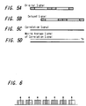
- FIG. 3 a symbol used in a DAB signal (digital audio broadcasting signal) is described.
- the symbol consists of a guard interval in a first part and an effective symbol in a later part.
- An end portion of the effective symbol, as shown by hatching in FIG. 3 includes the same signal portion as that of the guard interval and having the same duration as that of the guard interval.
- the DAB signal will be described in detail later on.
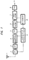
- the DAB receiver has an arrangement shown in FIG. 1. Specifically, an input signal of a DAB broadcasting wave is received by an antenna 1. This input signal is supplied from the antenna 1 to a front end circuit 2 arranged in a superheterodyne system, and the front end circuit 2 converts this supplied input signal into an intermediate frequency signal and supplies the intermediate frequency signal to an A/D converter circuit 3 which converts the supplied signal into a digital signal.
- the digital signal is supplied from the A/D converter 3 to an orthogonal demodulator 4, and the orthogonal demodulator 4 demodulates a baseband data and supplies the demodulated data to a fast Fourier transform (FFT) circuit 5.
- the FFT circuit 5 subjects the data to an orthogonal frequency division multiplex (OFDM) demodulation and supplies the OFDM-demodulated data to a Viterbi decoder 6.
- the Viterbi decoder 6 subjects the data to deinterleaving processing and error correction.
- a system control microcomputer 20 supplies a predetermined selection signal to the Viterbi decoder 6, thereby a channel selection (program selection) being carried out. Then, a digital audio data of a target channel is selected and then supplied to an audio decoder 7.
- the audio decoder 7 expands data in accordance with an MPEG standard.
- the decoder 7 converts the digital audio data of a target channel into an original data by data expansion and output the original digital audio data to a D/A converter 8.
- the D/A converter 8 converts the digital audio data into an analog audio signal and then supplies the analog audio signal to a terminal 9.
- a synchronization processing circuit 10 is formed of a circuit including a DSP and carries out an automatic frequency control (AFC) of the front-end circuit 2 and also processing for establishing synchronization in the FFT circuit 5.
- AFC automatic frequency control
- FIG. 2 is a block diagram thereof.
- the orthogonal demodulator 4 supplies an original signal (a DAB signal of mode 1) shown in FIG. 4A through an input terminal 11 to a delay means 12.
- the original signal from the input terminal 11 and a delayed signal (FIG. 4B) from the delay means 12 are supplied to a correlation means 13, which judges whether any correlation exists or not.
- the correlation means 13 produces a rectangular waveform correlation signal indicating that there exists a correlation (shown in FIG. 4C).
- the moving average means 14 When the correlation signal from the correlation means 13 is supplied to a moving average means 14 which calculates a moving average by the width of a time corresponding to the guard interval in the symbol, the moving average means 14 outputs a triangular waveform signal of a line symmetry in which, as shown in FIG 4D, such that at the rising edge of the rectangular correlation signal indicating that there exists a correlation it begins a rising inclination and at the falling edge of the correlation signal it begins a falling inclination.
- the output of the moving average means 14 is supplied to a comparing means 15, which compares it with a threshold level TH, as shown in FIG. 4D, having a level a little lower than the amplitude level of the triangular waveform signal actually obtained and, if it is higher than the threshold level TH, the comparing means 15 outputs to an output terminal 16 a discriminated signal indicating that the received input signal is a DAB signal.
- a threshold level TH as shown in FIG. 4D
- the comparing means 15 outputs to the output terminal 16 a discrimination signal which indicates that the input signal is not a DAB signal. Then, a signal output from the output terminal 16 is supplied to a microcomputer 20.
- a DAB signal of mode 1 as a typical example is shown in FIG. 7. In FIG. 7, the basic period T and time are both illustrated.
- the carrier indicated by 0 is the carrier of a center frequency (the period of this carrier is T)
- the carrier of the lowest frequency has 1536 waves and its data amount is 1536 ⁇ 2 bits, 48 CU (capacity unit) ⁇ 64 bits.
- Phase Reference Symbol Phase Reference Symbol
- TFPR Time Frequency Reference
- the FIC 4 consists of four FIBs (First Information Block) 4.1, 4.2, 4.3 and 4.4, each having the same continuation time.
- each period of the DAB signal is different depending on its mode, each period of mode 2 being 1/4 of each period of mode 1, each period of mode 3 being 1/8 of each period of mode 1, and each period of mode 4 being 1/2 of each period of mode 1.
- the original signal (FIG. 5A) from the input terminal 11 and the delayed signal (FIG. 5B) from the delay means 12 are supplied to the correlation means 13, which detects whether or not there exists any correlation.
- the correlation signal as is shown in FIG. 5C, indicating that there exists a correlation cannot be obtained and therefore, as is shown in FIG. 5D, the signal cannot be obtained from the moving average means 14. That is, it is less than the threshold TH and the comparing means 15 determines that there is not any correlation.
- the delay means is formed of a variable delay means for to sequentially varying the delay time ⁇ /n corresponding to the effective symbol period of a digital audio broadcasting of a plurality of different modes. While even when the delay time ⁇ /n corresponding to all the effective symbol periods of digital audio broadcasting of a plurality of different modes is varied, if it is not judged that there exists a correlation by an output of the comparing means does not detect that there exists any correlation, it is judged that the input signal is not to a digital audio broadcasting signal. If it is judged that there exists a correlation by the output of the comparing means, it is judged that the input signal is a digital audio broadcasting signal.
Abstract
Description
Claims (2)
- A discriminating apparatus for digital audio broadcasting, comprising:a delay means (12) for delaying an input signal by a time τ/n (where n =1, 2, 4, 8, and..., τ is a predetermined time) corresponding to a period of an effective symbol in a symbol;a correlation means (13) for judging whether any correlation exists or not between said input signal and a delayed signal from said delay means;a moving average means (14) for calculating a moving average of an output of said correlation means in a period corresponding to a guard interval in said symbol; anda comparing means (15) for comparing an output of said moving average means with a threshold level;wherein whether said input signal is a digital audio broadcasting signal or not is determined by an output of said comparing means.
- A discriminating apparatus according to claim 1, wherein said delay means (12) is a variable delay means for sequentially varying said delay time τ/n corresponding to effective symbol periods of a plurality of different modes of digital audio broadcasting and if it is determined that there is no correlation by an output of said comparing means when said delay time τ/n has been varied to correspond to all the effective symbol periods the plurality of different modes of digital audio broadcasting, and if it is determined that there exists a correlation by the output of said comparing means, it is judged that said input signal is a digital audio broadcasting signal.
Applications Claiming Priority (3)
| Application Number | Priority Date | Filing Date | Title |
|---|---|---|---|
| JP8302067A JPH10145324A (en) | 1996-11-13 | 1996-11-13 | Discrimination device for digital audio broadcast |
| JP302067/96 | 1996-11-13 | ||
| JP30206796 | 1996-11-13 |
Publications (2)
| Publication Number | Publication Date |
|---|---|
| EP0843431A2 true EP0843431A2 (en) | 1998-05-20 |
| EP0843431A3 EP0843431A3 (en) | 2001-09-05 |
Family
ID=17904523
Family Applications (1)
| Application Number | Title | Priority Date | Filing Date |
|---|---|---|---|
| EP97309063A Withdrawn EP0843431A3 (en) | 1996-11-13 | 1997-11-11 | Discriminating apparatus for digital audio broadcasting |
Country Status (5)
| Country | Link |
|---|---|
| US (1) | US6047034A (en) |
| EP (1) | EP0843431A3 (en) |
| JP (1) | JPH10145324A (en) |
| KR (1) | KR19980042347A (en) |
| CA (1) | CA2220647A1 (en) |
Cited By (2)
| Publication number | Priority date | Publication date | Assignee | Title |
|---|---|---|---|---|
| EP0978974A2 (en) * | 1998-08-04 | 2000-02-09 | Sony Corporation | DAB receiver with detection of the transmission mode |
| GB2501085A (en) * | 2012-04-11 | 2013-10-16 | Frontier Silicon Ltd | Determining whether a received signal is of OFDM construction |
Families Citing this family (8)
| Publication number | Priority date | Publication date | Assignee | Title |
|---|---|---|---|---|
| JPH11252038A (en) * | 1998-02-27 | 1999-09-17 | Sony Corp | Receiver for digital broadcasting |
| JP3513465B2 (en) | 2000-02-22 | 2004-03-31 | シャープ株式会社 | Wireless communication transmitter and wireless communication receiver |
| US20020065047A1 (en) * | 2000-11-30 | 2002-05-30 | Moose Paul H. | Synchronization, channel estimation and pilot tone tracking system |
| KR100640472B1 (en) | 2004-11-29 | 2006-10-30 | 삼성전자주식회사 | Apparatus and method estimating start of frame |
| US7734464B2 (en) * | 2005-05-20 | 2010-06-08 | Tektronix, Inc. | RF autocorrelation signal trigger generator |
| JPWO2008026376A1 (en) * | 2006-09-01 | 2010-01-14 | シャープ株式会社 | Demodulator, demodulator control method, demodulator control program, and recording medium recording demodulator control program |
| KR101255080B1 (en) * | 2009-12-21 | 2013-04-16 | 한국전자통신연구원 | Device and method for detection of timing synchronization |
| KR101327959B1 (en) * | 2011-12-27 | 2013-11-12 | 전자부품연구원 | Appratus and Method for Detecting Broadcasting Signal |
Citations (6)
| Publication number | Priority date | Publication date | Assignee | Title |
|---|---|---|---|---|
| DE4403408C1 (en) * | 1994-02-04 | 1995-02-23 | Grundig Emv | Method for identifying a transmission mode |
| JPH0799486A (en) * | 1993-09-28 | 1995-04-11 | Toshiba Corp | Ofdm reception synchronizing circuit |
| EP0653858A2 (en) * | 1993-11-16 | 1995-05-17 | Kabushiki Kaisha Toshiba | OFDM Synchronization demodulation circuit |
| EP0656706A2 (en) * | 1993-11-12 | 1995-06-07 | Kabushiki Kaisha Toshiba | Synchronisation of OFDM signals |
| EP0729250A2 (en) * | 1995-02-24 | 1996-08-28 | Kabushiki Kaisha Toshiba | OFDM transmission/reception system and transmitting/receiving apparatus |
| JPH09307599A (en) * | 1996-05-17 | 1997-11-28 | Pioneer Electron Corp | Digital broadcast receiver with transmission mode identification function |
Family Cites Families (4)
| Publication number | Priority date | Publication date | Assignee | Title |
|---|---|---|---|---|
| US5233632A (en) * | 1991-05-10 | 1993-08-03 | Motorola, Inc. | Communication system receiver apparatus and method for fast carrier acquisition |
| SE469678B (en) * | 1992-01-13 | 1993-08-16 | Ericsson Telefon Ab L M | SET FOR SYNCHRONIZATION AND CHANNEL TESTING IN TDMA RADIO SYSTEM |
| GB2309864A (en) * | 1996-01-30 | 1997-08-06 | Sony Corp | An equalizer and modulator using a training sequence and multiple correlation with a stored copy of the sequence |
| US5748686A (en) * | 1996-04-04 | 1998-05-05 | Globespan Technologies, Inc. | System and method producing improved frame synchronization in a digital communication system |
-
1996
- 1996-11-13 JP JP8302067A patent/JPH10145324A/en active Pending
-
1997
- 1997-11-11 EP EP97309063A patent/EP0843431A3/en not_active Withdrawn
- 1997-11-12 CA CA002220647A patent/CA2220647A1/en not_active Abandoned
- 1997-11-12 KR KR1019970059559A patent/KR19980042347A/en not_active Application Discontinuation
- 1997-11-12 US US08/968,133 patent/US6047034A/en not_active Expired - Fee Related
Patent Citations (6)
| Publication number | Priority date | Publication date | Assignee | Title |
|---|---|---|---|---|
| JPH0799486A (en) * | 1993-09-28 | 1995-04-11 | Toshiba Corp | Ofdm reception synchronizing circuit |
| EP0656706A2 (en) * | 1993-11-12 | 1995-06-07 | Kabushiki Kaisha Toshiba | Synchronisation of OFDM signals |
| EP0653858A2 (en) * | 1993-11-16 | 1995-05-17 | Kabushiki Kaisha Toshiba | OFDM Synchronization demodulation circuit |
| DE4403408C1 (en) * | 1994-02-04 | 1995-02-23 | Grundig Emv | Method for identifying a transmission mode |
| EP0729250A2 (en) * | 1995-02-24 | 1996-08-28 | Kabushiki Kaisha Toshiba | OFDM transmission/reception system and transmitting/receiving apparatus |
| JPH09307599A (en) * | 1996-05-17 | 1997-11-28 | Pioneer Electron Corp | Digital broadcast receiver with transmission mode identification function |
Cited By (5)
| Publication number | Priority date | Publication date | Assignee | Title |
|---|---|---|---|---|
| EP0978974A2 (en) * | 1998-08-04 | 2000-02-09 | Sony Corporation | DAB receiver with detection of the transmission mode |
| EP0978974A3 (en) * | 1998-08-04 | 2001-10-17 | Sony Corporation | DAB receiver with detection of the transmission mode |
| US6563896B1 (en) | 1998-08-04 | 2003-05-13 | Sony Corporation | Digital broadcast receiver and receiving method |
| GB2501085A (en) * | 2012-04-11 | 2013-10-16 | Frontier Silicon Ltd | Determining whether a received signal is of OFDM construction |
| GB2501085B (en) * | 2012-04-11 | 2016-06-22 | Frontier Silicon Ltd | A method of, and receiver for, detecting a broadcast OFDM signal |
Also Published As
| Publication number | Publication date |
|---|---|
| EP0843431A3 (en) | 2001-09-05 |
| KR19980042347A (en) | 1998-08-17 |
| US6047034A (en) | 2000-04-04 |
| JPH10145324A (en) | 1998-05-29 |
| CA2220647A1 (en) | 1998-05-13 |
Similar Documents
| Publication | Publication Date | Title |
|---|---|---|
| US6993084B1 (en) | Coarse frequency synchronisation in multicarrier systems | |
| US6408038B1 (en) | Receiver and receiving circuit | |
| US6108353A (en) | Demodulating apparatus | |
| JP4164609B2 (en) | Null symbol position detection method, null symbol position detection apparatus, and receiver | |
| US6563896B1 (en) | Digital broadcast receiver and receiving method | |
| US6047034A (en) | Discriminating apparatus for digital audio broadcasting | |
| KR100429696B1 (en) | Process for transferring digital data via interference-affected radio channels and device for receiving digital data transmitted via interference-affected radio channels | |
| US5953649A (en) | Signal acquisition in a satellite telephone system | |
| US6549589B1 (en) | Digital audio broadcasting receiver | |
| JP2879034B1 (en) | OFDM receiver | |
| EP1032994A1 (en) | Method and device for change of reception frequency in a digital audio broadcasting system receiver | |
| EP1148684A2 (en) | Antenna switching in a receiver for digital broadcasts | |
| US6836518B1 (en) | Synchronization control method for receiver apparatus of data transmission system utilizing orthogonal frequency division multiplex, and data transmission system | |
| EP0938199A2 (en) | Means for determining available reception frequencies in a receiver for the reception of digital broadcasts | |
| JP3946932B2 (en) | OFDM receiver | |
| JP3514624B2 (en) | Digital broadcast receiver | |
| EP0944193B1 (en) | Receiver for the reception of digital broadcasts | |
| EP0944213B1 (en) | Digital broadcast receiver | |
| JP2001136146A (en) | Digital broadcast receiver | |
| JP3363764B2 (en) | OFDM broadcast receiver | |
| JP3568186B2 (en) | Digital broadcast receiver | |
| JP3514625B2 (en) | Digital broadcast receiver | |
| JP3781477B2 (en) | Digital audio broadcast receiver | |
| JP2001285239A (en) | Peak detection circuit | |
| JPH11340945A (en) | Diversity receiver |
Legal Events
| Date | Code | Title | Description |
|---|---|---|---|
| PUAI | Public reference made under article 153(3) epc to a published international application that has entered the european phase |
Free format text: ORIGINAL CODE: 0009012 |
|
| AK | Designated contracting states |
Kind code of ref document: A2 Designated state(s): AT BE CH DE DK ES FI FR GB GR IE IT LI LU MC NL PT SE |
|
| AX | Request for extension of the european patent |
Free format text: AL;LT;LV;MK;RO;SI |
|
| PUAL | Search report despatched |
Free format text: ORIGINAL CODE: 0009013 |
|
| AK | Designated contracting states |
Kind code of ref document: A3 Designated state(s): AT BE CH DE DK ES FI FR GB GR IE IT LI LU MC NL PT SE |
|
| AX | Request for extension of the european patent |
Free format text: AL;LT;LV;MK;RO;SI |
|
| RIC1 | Information provided on ipc code assigned before grant |
Free format text: 7H 04H 1/00 A, 7H 04L 27/00 B, 7H 04L 25/02 B |
|
| 17P | Request for examination filed |
Effective date: 20020206 |
|
| AKX | Designation fees paid |
Free format text: DE FR GB |
|
| STAA | Information on the status of an ep patent application or granted ep patent |
Free format text: STATUS: THE APPLICATION HAS BEEN WITHDRAWN |
|
| 18W | Application withdrawn |
Withdrawal date: 20020927 |