EP0843288A2 - Improvements in or relating to gas meters - Google Patents
Improvements in or relating to gas meters Download PDFInfo
- Publication number
- EP0843288A2 EP0843288A2 EP97117727A EP97117727A EP0843288A2 EP 0843288 A2 EP0843288 A2 EP 0843288A2 EP 97117727 A EP97117727 A EP 97117727A EP 97117727 A EP97117727 A EP 97117727A EP 0843288 A2 EP0843288 A2 EP 0843288A2
- Authority
- EP
- European Patent Office
- Prior art keywords
- module
- meter unit
- add
- gas
- base meter
- Prior art date
- Legal status (The legal status is an assumption and is not a legal conclusion. Google has not performed a legal analysis and makes no representation as to the accuracy of the status listed.)
- Granted
Links
Images

Classifications
-
- G—PHYSICS
- G07—CHECKING-DEVICES
- G07F—COIN-FREED OR LIKE APPARATUS
- G07F7/00—Mechanisms actuated by objects other than coins to free or to actuate vending, hiring, coin or paper currency dispensing or refunding apparatus
- G07F7/08—Mechanisms actuated by objects other than coins to free or to actuate vending, hiring, coin or paper currency dispensing or refunding apparatus by coded identity card or credit card or other personal identification means
- G07F7/0866—Mechanisms actuated by objects other than coins to free or to actuate vending, hiring, coin or paper currency dispensing or refunding apparatus by coded identity card or credit card or other personal identification means by active credit-cards adapted therefor
-
- G—PHYSICS
- G07—CHECKING-DEVICES
- G07F—COIN-FREED OR LIKE APPARATUS
- G07F15/00—Coin-freed apparatus with meter-controlled dispensing of liquid, gas or electricity
- G07F15/001—Coin-freed apparatus with meter-controlled dispensing of liquid, gas or electricity for gas
-
- G—PHYSICS
- G07—CHECKING-DEVICES
- G07F—COIN-FREED OR LIKE APPARATUS
- G07F7/00—Mechanisms actuated by objects other than coins to free or to actuate vending, hiring, coin or paper currency dispensing or refunding apparatus
- G07F7/08—Mechanisms actuated by objects other than coins to free or to actuate vending, hiring, coin or paper currency dispensing or refunding apparatus by coded identity card or credit card or other personal identification means
- G07F7/0873—Details of the card reader
Definitions
- the present invention relates to utility metering apparatus and in particular to gas meters.
- the original gas meter is a mechanical device arranged to measure the quantity of gas supplied and register that amount on a mechanical display.
- These types of gas meters are being superseded by electronic meters which use acoustic wave devices to measure the flow of gas through the meter which generate signals which are interpreted by a data processor, conveniently a microprocessor arranged to drive electronic displays to give an indication of the amount used.
- a typical electronic gas meter is described in the applicant's co-pending patent application number GB9524684.9 which describes a modular gas meter including a base meter unit having a gas valve to control the supply of gas, and an add-on module which changes the functionality of the base meter unit.
- Such add-on modules may be for pre-payment function or remote meter reading functions.
- Such meters use an optical communication port to enable the microprocessor to be externally accessed without the need for hard wire electrical connections which could prove a danger in the gas environment.
- An aim of the present invention is to utilise this electronic gas meter and provide means whereby it can easily be modified in order to easily change its functionality.
- an electronic gas meter for delivering a quantity of gas to a consumer, said gas meter comprising a base meter unit having a digital display to visibly indicate the amount of gas a consumer has used and an optical data port via which access to electronic circuitry within the base meter unit is provided for data communication purposes, a battery supply for powering the electronic circuitry within the base meter unit and means for securing the battery supply within the base meter unit, characterised in that the base meter unit is provided with latching means whereby an add-on module is securely attached to the base meter unit permitting the add-on module to communicate with the base meter unit.
- the latching means may comprise three recesses which are provided towards a front face of the base meter unit at positions close to the centre upper edge and lower edge and at an outer edge of the base meter unit.
- the add-on module may comprise projections which are adapted to be accommodated within a respective recess to enable the add-on module to be easily slipped onto the base meter unit and secured therewith.
- the add-on module may include an orifice for accommodating a retaining means which is arranged to be in register with an orifice within the battery cover to enable the additional module and the battery cover to be secured by a single retaining means.
- gas meters In the gas meter environment there are different types of gas meters which can be used in different circumstances. For example there can be a basic gas meter whereby the meter registers the amount of gas used and requires a meter reader to physically attend the meter and record the reading thereof in order to bill the customer. There are other types of gas meter such as pre-payment meters whereby coins are deposited in the meter in order to allow the consumer to have access to a quantity of gas. There is a further type of pre-payment meter whereby the consumer purchases a card which is in turn inserted into a slot within the meter in order to allow that meter to deliver the quantity of gas up to the value of the card inserted therein.
- pre-payment meters whereby the consumer purchases a card which is in turn inserted into a slot within the meter in order to allow that meter to deliver the quantity of gas up to the value of the card inserted therein.
- the present invention relates to an improved form of modular meter and seeks to make the task of fitting different modules easier.
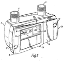
- a meter as shown in Figure 1 can be conveniently described as a base meter unit which when connected to the supply in a customer's premises does not need to be removed in order to adapt the base meter unit for other functions.
- the base meter unit 2 comprises a gas inlet port 4 and a gas outlet port 6 which respectively are connected to the gas mains inlet and outlet supply to a premises.
- the base meter unit has a front cover 8 secured to the meter module 2 by two retaining means 10, 12.
- the means 10, also serves to secure a battery cover 14.
- a window 16 is provided for viewing access to a digital display 18 and for providing access to an optical data port 20.
- the front cover 8 is provided with latching means in the form of three recesses 22, 24, 26. These recesses may be of any suitable shape and are arranged to receive a corresponding projection which extends from the rearward side of an additional module which is to be connected to the base meter unit 2.
- FIG 2 there is shown a base meter unit 2 as described with reference to Figure 1 having an additional module 28 connected thereto.
- the module 28 is of one example and that different modules providing different functions may be connected to the base meter unit 2.
- the add-on module 28 may be secured by the retaining means 30 which conveniently is in register with the retaining means 10 that would retain the battery cover 14 as shown in Figure 1. Therefore the module 28 and the battery cover 14 (Figure 1) is retained to the base meter unit 2 by virtue of a single retaining means, which may be a screw which passes through an orifice therein. This has the added benefit that the add-on module 28 can be easily removed together with the battery cover 14 to facilitate quick and easy battery replacement.
- the recesses 22, 24, 26 may conveniently be of any shape that affords strong structural support, and by having the three recesses in the position shown the additional add-on modules 28 can be connected to the base meter unit 2 directly from the front of the meter by partially superimposing the add-on module 28 over the front of the base meter unit 2 and sliding the add-on module from the right of the base meter unit 2, when viewed from the front of the base meter unit, to the left thus providing a quick and easy means facilitating the connection and disconnection of the add-on module 28.
- This is particularly useful where the base meter unit 2 is fitted in a meter box having limited side access.
- the add-on module 28 may include a microprocessor and other electronic circuitry depending upon its function and this circuitry will communicate with the electronic circuitry within the base meter unit 2 by way of an optical data port on the reverse side of the add-on module 28, which will be in register with the optical data port 20 on the base meter unit 2 when the add-on module 28 is fitted to the base meter unit 2.
- the invention has the following advantages.
- the add-on module fitting and removal requires no changes to wiring or pipe work.
- the base meter unit 2 can be changed to act like a credit meter or a pre-payment meter for example merely by replacing one add-on module with another which performs a different function. No additional complexity is experienced when changing the battery housed within the base meter unit 2.
- the use of an optical data port between the base meter unit 2 and the add-on module 28 means that approval of such equipment by the regulatory authorities is greatly simplified, because the use of optical data ports prevent interference effects that could influence the metrology of the base.
Abstract
Description
Claims (7)
- An electronic gas meter for delivering a quantity of gas to a consumer, said gas meter comprising a base meter unit having a digital display to visibly indicate the amount of gas a consumer has used and an optical data port via which access to electronic circuitry within the base meter unit is provided for data communication purposes, a battery supply for powering the electronic circuitry within the base meter unit and means for securing the battery supply within the base meter unit, characterised in that the base meter unit is provided with latching means whereby an add-on module is securely attached to the base meter unit permitting the add-on module to communicate with the base meter unit.
- A gas meter as claimed in Claim 1, wherein the latching means comprises three recesses which are provided towards a front face of the base meter unit at positions close to the centre upper edge and lower edge and at an outer edge of the base meter unit, whereby said add-on module comprises projections which are adapted to be accommodated within a respective recess to enable the add-on module to be easily slipped on to the base meter unit and secured therewith.
- A gas meter as claimed in Claim 2, wherein the add-on module includes an orifice for accommodating a retaining means which is arranged to be in register with an orifice within the battery cover to enable the additional module and the battery cover to be secured by a single retaining means.
- A gas meter as claimed in Claim 3, wherein the add-on module is provided an optical data port which is arranged to be in register with the optical data port on the base meter unit when the add-on module is securely positioned onto the base meter unit.
- A gas meter as claimed in Claim 4, wherein the add-on module is a pre-payment module.
- A gas meter as claimed in Claim 4, wherein the add-on module is a credit module.
- A gas meter substantially as hereinbefore described with reference to the accompanying drawings.
Applications Claiming Priority (2)
| Application Number | Priority Date | Filing Date | Title |
|---|---|---|---|
| GB9623769 | 1996-11-15 | ||
| GB9623769A GB2319342B (en) | 1996-11-15 | 1996-11-15 | Improvements in or relating to gas meters |
Publications (3)
| Publication Number | Publication Date |
|---|---|
| EP0843288A2 true EP0843288A2 (en) | 1998-05-20 |
| EP0843288A3 EP0843288A3 (en) | 2000-07-05 |
| EP0843288B1 EP0843288B1 (en) | 2006-08-16 |
Family
ID=10802980
Family Applications (1)
| Application Number | Title | Priority Date | Filing Date |
|---|---|---|---|
| EP97117727A Expired - Lifetime EP0843288B1 (en) | 1996-11-15 | 1997-10-14 | Improvements in or relating to gas meters |
Country Status (4)
| Country | Link |
|---|---|
| EP (1) | EP0843288B1 (en) |
| AT (1) | ATE336769T1 (en) |
| DE (1) | DE69736508D1 (en) |
| GB (1) | GB2319342B (en) |
Cited By (2)
| Publication number | Priority date | Publication date | Assignee | Title |
|---|---|---|---|---|
| EP1067367A1 (en) * | 1999-07-03 | 2001-01-10 | GMT GASELAN Gas-, Mess- und Regeltechnik GmbH & Co. KG | Device for releasing or blocking of gas delivery |
| CN106781046A (en) * | 2016-12-21 | 2017-05-31 | 杨启梁 | Internet of things gas meter |
Families Citing this family (1)
| Publication number | Priority date | Publication date | Assignee | Title |
|---|---|---|---|---|
| GB0809126D0 (en) * | 2008-05-20 | 2008-06-25 | Pilot Systems London Ltd | Metering energy use |
Citations (4)
| Publication number | Priority date | Publication date | Assignee | Title |
|---|---|---|---|---|
| EP0431222A1 (en) * | 1989-12-04 | 1991-06-12 | Siemens Aktiengesellschaft | Apparatus for measuring gaz consumption |
| EP0468236A1 (en) * | 1990-07-27 | 1992-01-29 | G. Kromschröder Aktiengesellschaft | Counting train, especially for gas meters |
| EP0616201A1 (en) * | 1993-03-19 | 1994-09-21 | Landis & Gyr Business Support AG | Housing for a heat meter |
| DE29515396U1 (en) * | 1994-09-16 | 1995-11-30 | Amic Ind Ltd | Housing for a power supply device |
-
1996
- 1996-11-15 GB GB9623769A patent/GB2319342B/en not_active Expired - Fee Related
-
1997
- 1997-10-14 DE DE69736508T patent/DE69736508D1/en not_active Expired - Lifetime
- 1997-10-14 EP EP97117727A patent/EP0843288B1/en not_active Expired - Lifetime
- 1997-10-14 AT AT97117727T patent/ATE336769T1/en not_active IP Right Cessation
Patent Citations (4)
| Publication number | Priority date | Publication date | Assignee | Title |
|---|---|---|---|---|
| EP0431222A1 (en) * | 1989-12-04 | 1991-06-12 | Siemens Aktiengesellschaft | Apparatus for measuring gaz consumption |
| EP0468236A1 (en) * | 1990-07-27 | 1992-01-29 | G. Kromschröder Aktiengesellschaft | Counting train, especially for gas meters |
| EP0616201A1 (en) * | 1993-03-19 | 1994-09-21 | Landis & Gyr Business Support AG | Housing for a heat meter |
| DE29515396U1 (en) * | 1994-09-16 | 1995-11-30 | Amic Ind Ltd | Housing for a power supply device |
Cited By (3)
| Publication number | Priority date | Publication date | Assignee | Title |
|---|---|---|---|---|
| EP1067367A1 (en) * | 1999-07-03 | 2001-01-10 | GMT GASELAN Gas-, Mess- und Regeltechnik GmbH & Co. KG | Device for releasing or blocking of gas delivery |
| CN106781046A (en) * | 2016-12-21 | 2017-05-31 | 杨启梁 | Internet of things gas meter |
| CN106781046B (en) * | 2016-12-21 | 2019-02-22 | 杨启梁 | Internet of Things gas meter |
Also Published As
| Publication number | Publication date |
|---|---|
| EP0843288B1 (en) | 2006-08-16 |
| DE69736508D1 (en) | 2006-09-28 |
| GB2319342B (en) | 2000-12-13 |
| EP0843288A3 (en) | 2000-07-05 |
| GB9623769D0 (en) | 1997-01-08 |
| ATE336769T1 (en) | 2006-09-15 |
| GB2319342A (en) | 1998-05-20 |
Similar Documents
| Publication | Publication Date | Title |
|---|---|---|
| US4777354A (en) | System for controlling the supply of utility services to consumers | |
| US9175979B2 (en) | Prepayment system for supplying water or gas by means of a wireless intelligent card and meter for said system | |
| US7298134B2 (en) | Electrical-energy meter adaptable for optical communication with various external devices | |
| CA2827908A1 (en) | Prepayment system for energy meters using contactless intelligent cards with automatic device of energy shut off | |
| US20150241480A1 (en) | Power meter configured for rear and side expansion | |
| EP0762349B1 (en) | Improvements in or relating to gas meters | |
| EP0843288B1 (en) | Improvements in or relating to gas meters | |
| EP0742443B1 (en) | Improvements in or relating to electricity meters | |
| JPH01255100A (en) | Remote meter reading device for gas meter | |
| US6243693B1 (en) | Token-operated apparatus for communal prepayment water management | |
| EP0742444A2 (en) | Improvements in or relating to electricity meters | |
| GB2313945A (en) | Fluid flow control device | |
| KR20000014887A (en) | System for automatically collecting a gas rate | |
| CN109410452A (en) | A kind of intelligent IC card water meter | |
| SI0752589T1 (en) | Electricity meter | |
| JPH1186099A (en) | Advance payment system supply control device | |
| JPH1153636A (en) | Power supply type gas meter | |
| GB2342484A (en) | Prepayment metering system | |
| GB2295682A (en) | Improvements in or relating to electricity meters | |
| JP2589749B2 (en) | Prepay system for heat supply | |
| JPH0343894A (en) | Prepayment gas meter system using prepaid card | |
| KR970016539A (en) | Card type water metering method and apparatus | |
| KR20050036516A (en) | Gas metering system | |
| JPH11120435A (en) | Gas supply controller |
Legal Events
| Date | Code | Title | Description |
|---|---|---|---|
| PUAI | Public reference made under article 153(3) epc to a published international application that has entered the european phase |
Free format text: ORIGINAL CODE: 0009012 |
|
| AK | Designated contracting states |
Kind code of ref document: A2 Designated state(s): AT DE FR GB IT NL SE |
|
| 17P | Request for examination filed |
Effective date: 19981113 |
|
| PUAL | Search report despatched |
Free format text: ORIGINAL CODE: 0009013 |
|
| AK | Designated contracting states |
Kind code of ref document: A3 Designated state(s): AT BE CH DE DK ES FI FR GB GR IE IT LI LU MC NL PT SE |
|
| RAP1 | Party data changed (applicant data changed or rights of an application transferred) |
Owner name: SIEMENS METERING LIMITED |
|
| AKX | Designation fees paid |
Free format text: AT DE FR GB IT NL SE |
|
| RAP1 | Party data changed (applicant data changed or rights of an application transferred) |
Owner name: LANDIS+GYR LIMITED |
|
| 17Q | First examination report despatched |
Effective date: 20041022 |
|
| GRAP | Despatch of communication of intention to grant a patent |
Free format text: ORIGINAL CODE: EPIDOSNIGR1 |
|
| GRAS | Grant fee paid |
Free format text: ORIGINAL CODE: EPIDOSNIGR3 |
|
| GRAA | (expected) grant |
Free format text: ORIGINAL CODE: 0009210 |
|
| AK | Designated contracting states |
Kind code of ref document: B1 Designated state(s): AT DE FR GB IT NL SE |
|
| PG25 | Lapsed in a contracting state [announced via postgrant information from national office to epo] |
Ref country code: IT Free format text: LAPSE BECAUSE OF FAILURE TO SUBMIT A TRANSLATION OF THE DESCRIPTION OR TO PAY THE FEE WITHIN THE PRE;WARNING: LAPSES OF ITALIAN PATENTS WITH EFFECTIVE DATE BEFORE 2007 MAY HAVE OCCURRED AT ANY TIME BEFORE 2007. THE CORRECT EFFECTIVE DATE MAY BE DIFFERENT FROM THE ONE RECORDED.SCRIBED TIME-LIMIT Effective date: 20060816 Ref country code: AT Free format text: LAPSE BECAUSE OF FAILURE TO SUBMIT A TRANSLATION OF THE DESCRIPTION OR TO PAY THE FEE WITHIN THE PRESCRIBED TIME-LIMIT Effective date: 20060816 |
|
| REG | Reference to a national code |
Ref country code: GB Ref legal event code: FG4D |
|
| REF | Corresponds to: |
Ref document number: 69736508 Country of ref document: DE Date of ref document: 20060928 Kind code of ref document: P |
|
| RAP2 | Party data changed (patent owner data changed or rights of a patent transferred) |
Owner name: LANDIS+GYR LIMITED |
|
| PG25 | Lapsed in a contracting state [announced via postgrant information from national office to epo] |
Ref country code: SE Free format text: LAPSE BECAUSE OF FAILURE TO SUBMIT A TRANSLATION OF THE DESCRIPTION OR TO PAY THE FEE WITHIN THE PRESCRIBED TIME-LIMIT Effective date: 20061116 |
|
| PG25 | Lapsed in a contracting state [announced via postgrant information from national office to epo] |
Ref country code: DE Free format text: LAPSE BECAUSE OF FAILURE TO SUBMIT A TRANSLATION OF THE DESCRIPTION OR TO PAY THE FEE WITHIN THE PRESCRIBED TIME-LIMIT Effective date: 20061117 |
|
| NLT2 | Nl: modifications (of names), taken from the european patent patent bulletin |
Owner name: LANDIS+GYR LIMITED Effective date: 20061102 |
|
| EN | Fr: translation not filed | ||
| PLBE | No opposition filed within time limit |
Free format text: ORIGINAL CODE: 0009261 |
|
| STAA | Information on the status of an ep patent application or granted ep patent |
Free format text: STATUS: NO OPPOSITION FILED WITHIN TIME LIMIT |
|
| 26N | No opposition filed |
Effective date: 20070518 |
|
| PG25 | Lapsed in a contracting state [announced via postgrant information from national office to epo] |
Ref country code: FR Free format text: LAPSE BECAUSE OF FAILURE TO SUBMIT A TRANSLATION OF THE DESCRIPTION OR TO PAY THE FEE WITHIN THE PRESCRIBED TIME-LIMIT Effective date: 20070511 |
|
| PG25 | Lapsed in a contracting state [announced via postgrant information from national office to epo] |
Ref country code: FR Free format text: LAPSE BECAUSE OF FAILURE TO SUBMIT A TRANSLATION OF THE DESCRIPTION OR TO PAY THE FEE WITHIN THE PRESCRIBED TIME-LIMIT Effective date: 20060816 |
|
| PGFP | Annual fee paid to national office [announced via postgrant information from national office to epo] |
Ref country code: NL Payment date: 20081031 Year of fee payment: 12 |
|
| REG | Reference to a national code |
Ref country code: NL Ref legal event code: V1 Effective date: 20100501 |
|
| PG25 | Lapsed in a contracting state [announced via postgrant information from national office to epo] |
Ref country code: NL Free format text: LAPSE BECAUSE OF NON-PAYMENT OF DUE FEES Effective date: 20100501 |
|
| PGFP | Annual fee paid to national office [announced via postgrant information from national office to epo] |
Ref country code: GB Payment date: 20161020 Year of fee payment: 20 |
|
| REG | Reference to a national code |
Ref country code: GB Ref legal event code: PE20 Expiry date: 20171013 |
|
| PG25 | Lapsed in a contracting state [announced via postgrant information from national office to epo] |
Ref country code: GB Free format text: LAPSE BECAUSE OF EXPIRATION OF PROTECTION Effective date: 20171013 |