EP0843241B1 - Dispositif de commande d'action et procédé d'initialisation du dispositif - Google Patents
Dispositif de commande d'action et procédé d'initialisation du dispositif Download PDFInfo
- Publication number
- EP0843241B1 EP0843241B1 EP97810821A EP97810821A EP0843241B1 EP 0843241 B1 EP0843241 B1 EP 0843241B1 EP 97810821 A EP97810821 A EP 97810821A EP 97810821 A EP97810821 A EP 97810821A EP 0843241 B1 EP0843241 B1 EP 0843241B1
- Authority
- EP
- European Patent Office
- Prior art keywords
- action
- chronometers
- duration
- counting
- control
- Prior art date
- Legal status (The legal status is an assumption and is not a legal conclusion. Google has not performed a legal analysis and makes no representation as to the accuracy of the status listed.)
- Expired - Lifetime
Links
Images








Classifications
-
- G—PHYSICS
- G05—CONTROLLING; REGULATING
- G05B—CONTROL OR REGULATING SYSTEMS IN GENERAL; FUNCTIONAL ELEMENTS OF SUCH SYSTEMS; MONITORING OR TESTING ARRANGEMENTS FOR SUCH SYSTEMS OR ELEMENTS
- G05B19/00—Program-control systems
- G05B19/02—Program-control systems electric
- G05B19/04—Program control other than numerical control, i.e. in sequence controllers or logic controllers
- G05B19/10—Program control other than numerical control, i.e. in sequence controllers or logic controllers using selector switches
- G05B19/106—Program control other than numerical control, i.e. in sequence controllers or logic controllers using selector switches for selecting a program, variable or parameter
Definitions
- the invention relates to an action control device. and a method for initializing the device.
- Programmable devices with control clock actions such as waking up in the morning or rack blackout switches glazed, like blinds, are known in the art prior. These devices allow programming the execution of one or more actions determined at a specific time or at several different times. For example, in the case of an alarm clock, the user can set the alarm to ring at a fixed time or two rings at different times. For a bay window obscuring device such as blinds, the programmed actions can be the blinds open at a specific time in the morning and closing at another specific time at the end of day. In summer, it can even be beneficial to program an opening in the morning, a closing towards noon, a new opening in the late afternoon and finally closing in the evening.
- These known devices generally include several human / machine interfaces, including one keyboard and screen, to allow on the one hand to the user to enter the set times at program and on the other hand to view them, as control.
- the programming of these devices is carried out as follows: the user puts the device in question in a mode programming by a specific action on it, then the user enters the time to memorize and finally by another action on the device validates the time thus programmed.
- Patent application GB 2 245 994 (A) describes another type of device for centralized control heater including an interface box with two pairs of buttons to activate or deactivate the heating twice a day. The action of one of the buttons - regardless of its duration- automatically saves the time. The command associated with this button will be executed at the same time the following day.
- the buttons are intended only for the programming and not manual control. Two other buttons are used to change temporarily the heating status without modifying the programmed times: one to reverse the current system command and the other to extend the state in a predetermined period which the system is located.
- the object of the invention is to simplify the device control and its initialization process. This goal is reached by the device of claim 1 and by the method of claim 8.
- the control device comprises: a box, at least two buttons each controlling a action, inputs / outputs, calculator, means memory, power supply, clock, and it is characterized in that it further comprises at minus three timers, the first of these chronometers being initialized and activated by pressing on one of said control buttons and measuring the duration of said press, and each of the other timers being associated with the action controlled by one of the buttons control via the computer, so that if the duration of pressing the control button is equal to or greater than a predetermined setpoint, the stopwatch associated with the action of the command button actuated is initialized and activated to perform repeated counting cycles of a predetermined duration, clocked by the clock, at the end of each of which the action the stopwatch is associated with is controlled on the device output.
- An advantage of the invention is that the user does not have no need to program order times in the device itself.
- the reference time is the one he is programming and the stopwatches with 24-hour counting cycles, the initialized command is repeated every 24 hours.
- the cost of the device is reduced since the man / machine interfaces are removed.
- Figure 1 is a block diagram of a device according to the invention controlling a roller shutter.
- Figure 2 is the flow diagram of the control process direct.
- Figure 3 is the flow diagram of the initiating a command cycle.
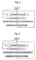
- Figure 4 is the flowchart of a control cycle climb.
- Figure 5 is the flowchart of a control cycle downhill.
- Figure 6 is a block diagram of a second mode of the invention.
- Figure 7 is the flow diagram of a procedure used when powering up the second mode execution.
- Figure 8 is a flow diagram of the method of for initiating command cycles according to the second mode of execution.
- Figure 9 is the flowchart of control cycles ascent or descent according to the second mode execution.
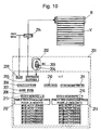
- FIG. 10 is the block diagram of an example according to the second mode of execution with numerical values.
- Figure 11 is a block diagram of a third mode of the invention.
- Figure 12 is a flow diagram of the for starting chronometers according to the third mode of carrying out the invention.
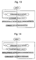
- Figure 13 is a flow diagram of a control cycle climb according to the third embodiment.
- Figure 14 is a flow diagram of a control cycle descent according to the third embodiment.
- Figure 15 is a procedure for initializing the third embodiment.
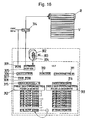
- Figure 16 is a block diagram of an example according to third embodiment with numeric values.
- control device is first described in reference to figure 1.
- This device includes a control unit 101 on which are three control buttons, the first 102 to control the climb, the second 103 to order a stop and the third 104 to order the descent. These buttons are linked in the housing to a logic processing unit (ULT) which includes an I / O interface 105, a computer 106, RAM memory 107, ROM memory 108, a power supply 109 and a clock 110.
- the unit processing logic further includes three stopwatches 111, 112 and 113 having functions distinct.
- the first stopwatch 111 allows determine whether the user’s press time on the up 102 or down 104 control button exceeds a specified setpoint, for example 5 seconds.
- a cycle of action command of rise if the user presses the control button up or down if the user presses the descent control button, is initialized and activated on the stopwatch 112 for the climb or on the stopwatch 113 for the descent respectively by the computer 106.
- this stopwatch counts for the duration of a cycle, for example 24 hours, repeatedly.
- the stopwatch is indeed initialized and activated again for a cycle of counting and the action is commanded at the exit of the device on the pilot 114 of the roller shutter V.
- This process begins with user support on an action command button, a climb or a downhill for example, and stopwatch 111 is initialized and activated. If the duration of support measured by the timer 111 exceeds the setpoint, for example 5 seconds, then the stopwatch associated with the action command on which the user is currently to press is initialized and activated to start count a 24 hour cycle. So whatever its state i.e. even if it is counting a cycle, a new cycle is started with this initialization. At any time, the user can therefore restart initialization and activation the stopwatch associated with an action.
- the device checks that the stopwatch 112 for the climb, or 113 for the descent, is activated. It then compares the value of counting of each activated stopwatch with the value of cycle setpoint. As soon as this value, 24 hours in the present case is reached for one of the chronometers active, it is initialized and activated again, a counting cycle begins again, and the action associated with stopwatch is ordered on exit 105 of device.
- the device checks whether the stopwatch 113 associated with the action of descent is active and then compares its count value with the cycle setpoint. As soon as this value is reached, the stopwatch 113 associated with the descent action is initialized and activated, a cycle counting starts again for stopwatch 113, and the descent action is commanded on the exit of the device.
- a counting cycle worth 24 hours each cycle begins when it has been initialized and activated and the action is repeated at the end of each 24-hour cycle hours.
- a second embodiment of the device is shown in Figures 6 to 10.
- the device is able to command several identical actions, for example several ascents and several descents, for the duration of a counting cycle.
- This mode can be particularly advantageous for a shutter control. Indeed, in summer, it it may be useful to mount the roller shutter early morning, to descend it around noon, to ascend it towards the middle of the afternoon and finally to descend it the evening.
- the device comprises a housing 201, on which of the control buttons 202, 203 and 204 are placed.
- Button 202 is the raise command, 203 la stop command and 204 the descent command.
- the housing 201 further includes a logic unit for processing which includes inputs / outputs 205, a computer 206, RAM 207 and ROM 208 memories, one power supply 209, a clock 210, a first stopwatch 211 intended to measure the duration of pressing a control button 202 or 204.
- the unit logic still has a table 212 of timers for the climb and a table 213 timers for lowering. Addressing means to access different timers are made up of an index of climb 215 and a descent index 216.
- This mode is differentiates from the first mode mainly by the number of timers used in tables 212 and 213.
- Table 212 of the chronometers for the climb indeed contains 7 chronometers, including indexes addresses have the values 2, 4, 6, 8, 10, 12 and 14.
- the timer table for the downhill 213 contains 7 stopwatches including indexes have the values 3, 5, 7, 9, 11, 13 and 15.
- the rise index 215 can therefore take the values pairs from 2 to 14 and the descent index 216 the values odd from 3 to 15 to point to each of chronometers.
- FIG 7. A device initialization procedure during its power up is shown in figure 7.
- the rise and fall indices 215, 216 are initialized so as to point to the first of the chronometers on each table 212, 213. They therefore have the values 2 and 3 respectively.
- This procedure can be programmed in the computer.
- This process begins like that shown in Figure 3, by pressing a user on a button action command.
- This support initializes and activates the first stopwatch measuring the duration of support, which allows to go to the initialization of cycles if the press exceeds 5 seconds.
- the calculator determines what type of action is chosen by the user, i.e. an ascent or descent. If the user initiated this process by pressing on the climb control button, then the device initializes and activates the stopwatch on which points the climb index. This index points always on the first stopwatch which is not activated. Indeed, during the first use of the device, the procedure shown in Figure 7 initializes the indexes so that they point to the first indexes of the tables.
- indexes are incremented of 2 after each initialization and activation of stopwatch so the pointer moves in the stopwatch table. As soon as the value of the index exceeds the maximum possible value for a table given, in this case 14 for the climb or 15 for the descent, it is reset to the value pointing to the first stopwatch on the table.
- the stopwatch the index was pointing at is initialized and activated, the index is then incremented by 2 and if this value exceeds 15, the index is initialized at the value corresponding to the first stopwatch of the descent table.
- This procedure first includes an instruction allowing to select all the chronometers one after the other. Then the procedure tests whether the selected timers is active and if the answer is negative, we return to the beginning of the procedure for the start again with the next stopwatch. If the answer is positive, we test the count value of it. As long as this value is not equal to 24 hours, the procedure starts again from the beginning for the stopwatch next. As soon as the count value reaches 24 hours, the selected stopwatch is initialized, the parity of its index is determined and if the index is even, the mounted command is sent, while if it is odd, the descent command is sent. The procedure then loops and starts again for the next stopwatch.
- Figure 10 shows an example with values of the device of FIG. 6 for the control of a roller shutter V.
- the different elements correspondents therefore have the same references. He is 7 am, user initiated climbs roller shutter V at 8 a.m. and 2 a.m. in the afternoon, and descents of the roller shutter V at noon and 8 p.m.
- the climb table 212 the first stopwatch and the second stopwatch are therefore active, since two rising actions have have been initialized, and they have a count value of 11 p.m. and 5 p.m.
- the first and second stopwatches are also active and they have the count values of 7 p.m. and 11 a.m. respectively.
- the next action that will take place is therefore a rise then that the next stopwatch that will finish its 24 hour counting cycle is the first climb stopwatch.
- this mode the device is able to calculate a average of the count values over a week.
- this mode will first be described by considering that only two different actions will be initialized during the duration of a counting cycle, as in the first embodiment described above.
- the device comprises a housing 301, on which control buttons 302, 303 and 304 are placed.
- the button 302 is the climb command
- 303 is the command stop and 304 the descent control.
- Case 301 further includes a logic processing unit which includes inputs / outputs 305, a computer 306, RAM 307 and ROM 308 memories, a power supply electric 309, clock 310, first stopwatch 311 intended to measure the duration of the press of a button 302 or 304.
- the logic unit still has a table 312 of the chronometers for the climb and a table 313 chronometers for the descent. Ways to access the different timers consist of a rise index 315 and an index descent 316.
- Each table 312 and 313 of chronometers includes in particular eight chronometers in all, of which the first seven each correspond to one day of the week and the eighth on which the average of the count values of the seven timers previous will be initialized.
- Initialization begins as described previously by pressing a device action button, pressing which starts the stopwatch 311. If this press exceeds 5 seconds, the system determines whether the button pressed is an up or down button. Then the stopwatch pointed to by the ascent or descent is initialized and activated and it begins a counting cycle. The index is incremented and its value tested. As long as this value is less than or equal to 14 for ascent or 15 for descent, the procedure starts again for stopwatches following. As soon as the value of the incremented index is greater than 14 or 15, this means that the table is full and the seven timers have been initialized and activated.
- the computer 306 calculates the mean deviation of the count values of the seven stopwatch and seven stopwatches stop table chronometers.
- the two gaps means obtained are then used to initialize and activate the eighth stopwatch of each table by taking into account this average difference.
- the actions are then controlled by the counting cycles of these last timers.
- the device first determines if the eighth stopwatch has been activated. As soon as this test is affirmative, it tests the stopwatch count value. As long as this value is not equal to 24 hours, the procedure start again. As soon as this value is equal to 24 hours, the eighth stopwatch is initialized and activated the action of ascending is commanded on the exit of the device.
- Figure 15 shows the initialization procedure indexes and eighth timers.
- the procedure is only active once when switching on the device. According to this procedure, the indexes are initialized respectively to the value 2 for the rise index and 3 for the rise index descent.
- the eighth stopwatch of each table is disabled so the procedure initialization of the seven timers of each table, described above with reference to Figure 12, can be executed. This procedure is useful on the one hand when the device is put into service for the first time and secondly to clear the average values of counting in force.
- a numerical example of average deviation calculation is described with reference to FIG. 16 for the control of a shutter rolling V.
- the calculation will only be made for a table of timers for the raising 312 of a roller shutter V, but this example can be transposed without other in the case of the descent of the roller shutter V.
- the climb index 315 must point to the last stopwatch of the climb table, therefore the eighth, for the device to calculate the average count value.
- the seven timers corresponding to each day of the week all have a different counting value in their 24-hour cycle since they were not initialized at the same time each day.
- the computer 306 determines the sum of the differences in hours and minutes (-2 for the first stopwatch, +1 for the second, + 3 for the third, -10 for the fourth etc.) divides this sum by the number of stopwatches ( 7 in this case), and initializes the eighth stopwatch taking into account this average difference.
- the average deviation is -1
- the count value with which the eighth counter is initialized is therefore 23:59.
- the roller shutter V will therefore go up in a minute.
- This mode of execution in which an average value of count is calculated can be generalized to a mode of execution in which several identical actions are to be executed every day of the week
- This mode of execution would correspond to a combination of the second and third embodiment.
- the chronometer table will have a matrix form, with for example eight columns (one per day of the week and the eighth column for the values means), and at least as many rows as the number of times an action must be ordered during the duration of a counting cycle.
- the gap means will be calculated for each row of the matrix, line corresponding to the same action but one day different.
- the addressing system should therefore be modified to allow access to each individual stopwatch in the table.
Landscapes
- Physics & Mathematics (AREA)
- General Physics & Mathematics (AREA)
- Engineering & Computer Science (AREA)
- Automation & Control Theory (AREA)
- Selective Calling Equipment (AREA)
- Vehicle Body Suspensions (AREA)
- Measurement Of Unknown Time Intervals (AREA)
- Electric Clocks (AREA)
- Measurement Of Predetermined Time Intervals (AREA)
- Programmable Controllers (AREA)
- Measuring Pulse, Heart Rate, Blood Pressure Or Blood Flow (AREA)
Description
En tenant compte de ce qui a été décrit ci-dessus, l'index de montée 315 doit pointer sur le dernier chronomètre de la table de montée, donc le huitième, pour que le dispositif calcule la valeur moyenne de comptage. Par rapport à une heure d'initialisation donnée, les sept chronomètres correspondant à chaque jour de la semaine ont tous une valeur de comptage différente dans leur cycle de 24 heures puisqu'ils n'ont pas été initialisés à la même heure chaque jour. Le calculateur 306 détermine la somme des écarts en heures et en minutes (-2 pour le premier chronomètre, +1 pour le deuxième, + 3 pour le troisième, -10 pour le quatrième etc.) divise cette somme par le nombre de chronomètres (7 dans ce cas), et initialise le huitième chronomètre tenant compte de cet écart moyen. Dans le cas représenté, l'écart moyen vaut -1, et la valeur de comptage avec laquelle le huitième compteur est initialisé est par conséquent 23H59. Le volet roulant V va donc monter dans une minute.
Claims (13)
- Dispositif de commande comportant un boítier (101,201,301), au moins deux boutons (102,104,202,204, 302,304) commandant chacun une action, des entrées/sorties (105,205,305), un calculateur (106,206, 306), des moyens de mémoire (107,108,207,208,307,308), une alimentation électrique (109,209,309), une horloge (110,210,310), ledit dispositif étant caractérisé en ce qu'il comporte en outre au moins trois chronomètres (111,112,113,211,311), le premier (111,211,311) de ces chronomètres étant initialisé et activé par un appui sur l'un desdits boutons de commande (102,104,202,204,302,304) et mesurant la durée dudit appui, et chacun des autres chronomètres (112,113) étant associé à l'action commandée par l'un des boutons de commande par l'intermédiaire du calculateur (106,206,306), de sorte que si la durée d'appui sur le bouton de commande est égale ou supérieure à une consigne prédéterminée, le chronomètre (112,113) associé à l'action du bouton de commande actionné est initialisé et activé pour effectuer des cycles de comptage répétés d'une durée prédéterminée, cadencés par l'horloge (110,210,310), au terme de chacun desquels l'action à laquelle le chronomètre est associé est commandée sur la sortie (105,205,305) du dispositif.
- Dispositif de commande selon la revendication 1, caractérisé en ce que le nombre de chronomètres associés à chaque action est égal au nombre de fois que ladite action doit être commandée pendant un cycle de comptage, et en ce que le dispositif comporte en outre des moyens d'adressage (212,213,215,216, 312,313,315,316) commandés par le calculateur permettant de sélectionner chacun desdits chronomètres pour l'initialiser et l'activer afin qu'il exécute des cycles de comptage successifs de sorte que l'action est commandée sur la sortie (205) du dispositif chaque fois que l'un des chronomètres associés termine son cycle de comptage.
- Dispositif selon la revendication 2, caractérisé en ce que le nombre de chronomètres associé à chaque action est égal huit, et en ce que à la fin d'un cycle d'adressage des sept premiers chronomètres, le calculateur (306) calcule une moyenne des valeurs de comptage des sept premiers chronomètres attribués à la même action de commande qui sont activés et initialise et active le huitième chronomètre avec cette valeur moyenne de comptage, de sorte que l'action est commandée sur la sortie (305) du dispositif chaque fois que le huitième chronomètre termine un cycle de comptage de valeur prédéterminée.
- Dispositif selon l'une des revendications précédentes, caractérisé en ce que la consigne prédéterminée est de 5 secondes.
- Dispositif selon l'une des revendications précédentes, caractérisé en ce que la durée d'un cycle de comptage est de 24 heures.
- Dispositif selon l'une des revendications 2 à 5, caractérisé en ce que les chronomètres sont placés dans des tables (212,213,312,313).
- Dispositif selon l'une des revendications précédentes, caractérisé en ce qu'il comporte en outre un interrupteur ayant une position de mode manuel et une position de mode automatique, la position en mode manuel désactivant l'influence des chronomètres de sorte que seul un appui effectif sur un bouton (102,104,202,204,302,304) de commande d'action commande une action sur la sortie (105,205,305) du dispositif.
- Procédé d'initialisation d'un dispositif selon l'une des revendications précédentes, caractérisé par les étapes suivantes:(a) action sur l'un des boutons de commande de l'appareil,(b) mesure de la durée de l'action de l'utilisateur au moyen d'un premier chronomètre,(c) comparaison de la durée de l'action avec une consigne prédéterminée,(d) dès que la durée de l'action sur le bouton est au moins égale à la durée de la consigne prédéterminée, initialisation et activation d'un cycle de comptage d'un chronomètre associé à l'interrupteur actionné,(e) comparaison de la valeur de comptage du chronomètre initialisé et activé avec la valeur d'un cycle de comptage prédéterminé,(f) dès que la valeur de comptage est égale à la valeur du cycle de comptage prédéterminé, initialisation et activation du chronomètre pour un nouveau cycle de comptage,(g) envoi de la commande associée à l'interrupteur actionné.
- Procédé selon la revendication 8, caractérisé en ce que l'étape (d) comporte les étapes intermédiaires suivantes:(d1) dès que la durée de l'action sur le bouton est au moins égale à la durée de la consigne prédéterminée, détermination de l'action commandée par le bouton activé,(d2) détermination de la valeur de l'index d'adressage,(d3) initialisation et activation d'un cycle de comptage du chronomètre sur lequel l'index pointe,(d4) incrément de l'index,(d5) si l'index est supérieur à une valeur maximale prédéterminée, réinitialisation de l'index.
- Procédé selon la revendication 9, caractérisé en ce que l'étape intermédiaire (d5) comporte les étapes suivantes:(1) si l'index est supérieur à une valeur maximale prédéterminée, calcul de l'écart moyen de tous les chronomètres associés à une action,(2) initialisation et activation d'un chronomètre avec un cycle de comptage tenant compte de l'écart moyen calculé.
- Procédé selon Tune des revendications 8 à 10, caractérisé en ce que la durée de la consigne prédéterminée est de 5 secondes.
- Procédé selon l'une des revendications 8 à 11, caractérisé en ce que la valeur d'un cycle de comptage prédéterminée est de 24 heures.
- Système de commande de volet roulant, comprenant un moteur entraínant un axe (R) autour duquel s'enroule un volet roulant (V), le système étant caractérisé en ce qu'il comprend un dispositif de commande selon l'une des revendications 1 à 7, un pilote (114,214,314) relié à la sortie (105,205,305) du dispositif de commande, le pilote (114,214,314) commandant le moteur en fonction de la commande issue de la sortie (105,205,305) du dispositif de commande.
Applications Claiming Priority (2)
| Application Number | Priority Date | Filing Date | Title |
|---|---|---|---|
| FR9613975A FR2756064B1 (fr) | 1996-11-15 | 1996-11-15 | Dispositif de commande d'action et procede d'initialisation du dispositif |
| FR9613975 | 1996-11-15 |
Publications (2)
| Publication Number | Publication Date |
|---|---|
| EP0843241A1 EP0843241A1 (fr) | 1998-05-20 |
| EP0843241B1 true EP0843241B1 (fr) | 2002-07-24 |
Family
ID=9497671
Family Applications (1)
| Application Number | Title | Priority Date | Filing Date |
|---|---|---|---|
| EP97810821A Expired - Lifetime EP0843241B1 (fr) | 1996-11-15 | 1997-11-03 | Dispositif de commande d'action et procédé d'initialisation du dispositif |
Country Status (5)
| Country | Link |
|---|---|
| EP (1) | EP0843241B1 (fr) |
| AT (1) | ATE221217T1 (fr) |
| DE (2) | DE69714191T4 (fr) |
| ES (1) | ES2117620T1 (fr) |
| FR (1) | FR2756064B1 (fr) |
Families Citing this family (2)
| Publication number | Priority date | Publication date | Assignee | Title |
|---|---|---|---|---|
| IT1306237B1 (it) * | 1998-12-03 | 2001-06-04 | Claber Spa | Temporizzatore elettronico programmabile ad autoapprendimento per ilcomando di un'elettrovalvola, particolarmente per impianti di |
| FR2797696B1 (fr) * | 1999-02-02 | 2001-11-09 | Bubendorff Sa | Dispositif de programmation horaire de commande de fermeture et/ou d'ouverture d'un systeme d'occultation ou similaire |
Family Cites Families (4)
| Publication number | Priority date | Publication date | Assignee | Title |
|---|---|---|---|---|
| US4677541A (en) * | 1984-09-24 | 1987-06-30 | Rauland-Borg Corporation | Programmable clock |
| US4852051A (en) * | 1986-07-18 | 1989-07-25 | The Toro Company | Flexible irrigation controller |
| GB9008651D0 (en) * | 1990-04-18 | 1990-06-13 | Sunvic Controls Ltd | Controller |
| US5511943A (en) * | 1994-11-09 | 1996-04-30 | Chang; Chin-Hsiung | Single-throw switch circuit controlling a ceiling fan and light assembly |
-
1996
- 1996-11-15 FR FR9613975A patent/FR2756064B1/fr not_active Expired - Fee Related
-
1997
- 1997-11-03 DE DE69714191T patent/DE69714191T4/de not_active Expired - Lifetime
- 1997-11-03 EP EP97810821A patent/EP0843241B1/fr not_active Expired - Lifetime
- 1997-11-03 AT AT97810821T patent/ATE221217T1/de not_active IP Right Cessation
- 1997-11-03 ES ES97810821T patent/ES2117620T1/es active Pending
- 1997-11-03 DE DE69714191A patent/DE69714191D1/de not_active Expired - Fee Related
Also Published As
| Publication number | Publication date |
|---|---|
| ATE221217T1 (de) | 2002-08-15 |
| FR2756064A1 (fr) | 1998-05-22 |
| DE69714191T4 (de) | 2003-08-14 |
| DE69714191D1 (de) | 2002-08-29 |
| EP0843241A1 (fr) | 1998-05-20 |
| ES2117620T1 (es) | 1998-08-16 |
| DE69714191T2 (de) | 2003-02-27 |
| FR2756064B1 (fr) | 1999-01-22 |
Similar Documents
| Publication | Publication Date | Title |
|---|---|---|
| EP0589353B1 (fr) | Pièce d'horlogerie analogique pouvant afficher des informations supplémentaires | |
| EP0439422A1 (fr) | Dispositif de sécurité pour volet roulant motorisé | |
| US4519692A (en) | Exposure and camera control | |
| EP0231451B1 (fr) | Montre électronique à deux moteurs pourvue d'un quantième perpétuel | |
| EP2075654A1 (fr) | Dispositif électronique portable destiné à afficher la valeur de variables à partir de mesures efffectuées par un capteur et présentant une fonction historique | |
| EP0735442A1 (fr) | Pièce d'horlogerie électronique analogique à disque de quantième multifunctionnel | |
| CH657182A5 (fr) | Dispositif automatique de commande d'un dispositif de protection solaire, notamment un store. | |
| CH666720A5 (fr) | Dispositif de commande pour volet roulant ou similaire a lames orientables. | |
| FR2584597A1 (fr) | Dispositif d'apprentissage de l'hygiene dentaire | |
| EP0843241A1 (fr) | Dispositif de commande d'action et procédé d'initialisation du dispositif | |
| EP0574637B1 (fr) | Procédé pour commander un organe déplaçable d'une unité fonctionnelle, et unité fonctionnelle pour sa mise en oeuvre | |
| EP0918266A1 (fr) | Dispositif de commande d'un moyen de protection solaire motorisé | |
| EP0039645B1 (fr) | Sèche-linge à programmateur électronique | |
| FR2547074A1 (fr) | Minuteur electronique | |
| FR2803049A1 (fr) | Dispositif de commande d'un appareil adapte a prendre un niveau selectionne parmi une plage de niveaux, procede de commande d'un volet roulant a l'aide d'un tel dispositif et module utilisateur pour un tel dispositif | |
| FR2560683A1 (fr) | Appareil pour mesurer la durete d'une matiere | |
| FR2755997A1 (fr) | Installation de protection solaire | |
| FR2508803A3 (fr) | Procede et dispositif de circuit pour commander des appareils d'irradiation | |
| FR2657646A1 (fr) | Dispositif de securite pour volet roulant motorise. | |
| FR2493552A1 (fr) | Compteur de temps numerique programmable et a fonction de chronodeclenchement | |
| FR2480958A1 (fr) | Piece d'horlogerie a affichage numerique commandee par une seule touche | |
| EP0130150A1 (fr) | Chronographe électronique, notamment montre-chronographe électronique, analogique, compteur de temps chronométrés | |
| EP0028414A1 (fr) | Pièce d'horlogerie comportant un dispositif de stockage | |
| FR2501471A1 (fr) | Dispositif de commande d'une chambre de fermentation pour boulangerie | |
| FR2725019A1 (fr) | Dispositif de mesure de distance. |
Legal Events
| Date | Code | Title | Description |
|---|---|---|---|
| PUAI | Public reference made under article 153(3) epc to a published international application that has entered the european phase |
Free format text: ORIGINAL CODE: 0009012 |
|
| AK | Designated contracting states |
Kind code of ref document: A1 Designated state(s): AT BE CH DE ES GB IT LI NL SE |
|
| AX | Request for extension of the european patent |
Free format text: AL;LT;LV;MK;RO;SI |
|
| REG | Reference to a national code |
Ref country code: ES Ref legal event code: BA2A Ref document number: 2117620 Country of ref document: ES Kind code of ref document: T1 |
|
| 17P | Request for examination filed |
Effective date: 19981113 |
|
| AKX | Designation fees paid |
Free format text: AT BE CH DE ES GB IT LI NL SE |
|
| RBV | Designated contracting states (corrected) |
Designated state(s): AT BE CH DE ES GB IT LI NL SE |
|
| 17Q | First examination report despatched |
Effective date: 20000928 |
|
| GRAG | Despatch of communication of intention to grant |
Free format text: ORIGINAL CODE: EPIDOS AGRA |
|
| GRAG | Despatch of communication of intention to grant |
Free format text: ORIGINAL CODE: EPIDOS AGRA |
|
| GRAH | Despatch of communication of intention to grant a patent |
Free format text: ORIGINAL CODE: EPIDOS IGRA |
|
| GRAH | Despatch of communication of intention to grant a patent |
Free format text: ORIGINAL CODE: EPIDOS IGRA |
|
| GRAA | (expected) grant |
Free format text: ORIGINAL CODE: 0009210 |
|
| AK | Designated contracting states |
Kind code of ref document: B1 Designated state(s): AT BE CH DE ES GB IT LI NL SE |
|
| PG25 | Lapsed in a contracting state [announced via postgrant information from national office to epo] |
Ref country code: NL Free format text: LAPSE BECAUSE OF FAILURE TO SUBMIT A TRANSLATION OF THE DESCRIPTION OR TO PAY THE FEE WITHIN THE PRESCRIBED TIME-LIMIT Effective date: 20020724 Ref country code: IT Free format text: LAPSE BECAUSE OF FAILURE TO SUBMIT A TRANSLATION OF THE DESCRIPTION OR TO PAY THE FEE WITHIN THE PRE;WARNING: LAPSES OF ITALIAN PATENTS WITH EFFECTIVE DATE BEFORE 2007 MAY HAVE OCCURRED AT ANY TIME BEFORE 2007. THE CORRECT EFFECTIVE DATE MAY BE DIFFERENT FROM THE ONE RECORDED.SCRIBED TIME-LIMIT Effective date: 20020724 Ref country code: GB Free format text: LAPSE BECAUSE OF FAILURE TO SUBMIT A TRANSLATION OF THE DESCRIPTION OR TO PAY THE FEE WITHIN THE PRESCRIBED TIME-LIMIT Effective date: 20020724 |
|
| REF | Corresponds to: |
Ref document number: 221217 Country of ref document: AT Date of ref document: 20020815 Kind code of ref document: T |
|
| REG | Reference to a national code |
Ref country code: GB Ref legal event code: FG4D Free format text: NOT ENGLISH |
|
| REG | Reference to a national code |
Ref country code: CH Ref legal event code: EP |
|
| REF | Corresponds to: |
Ref document number: 69714191 Country of ref document: DE Date of ref document: 20020829 |
|
| REG | Reference to a national code |
Ref country code: CH Ref legal event code: NV Representative=s name: BUGNION S.A. |
|
| PG25 | Lapsed in a contracting state [announced via postgrant information from national office to epo] |
Ref country code: SE Free format text: LAPSE BECAUSE OF FAILURE TO SUBMIT A TRANSLATION OF THE DESCRIPTION OR TO PAY THE FEE WITHIN THE PRESCRIBED TIME-LIMIT Effective date: 20021024 |
|
| PG25 | Lapsed in a contracting state [announced via postgrant information from national office to epo] |
Ref country code: BE Free format text: LAPSE BECAUSE OF NON-PAYMENT OF DUE FEES Effective date: 20021130 |
|
| NLV1 | Nl: lapsed or annulled due to failure to fulfill the requirements of art. 29p and 29m of the patents act | ||
| GBV | Gb: ep patent (uk) treated as always having been void in accordance with gb section 77(7)/1977 [no translation filed] |
Effective date: 20020724 |
|
| PG25 | Lapsed in a contracting state [announced via postgrant information from national office to epo] |
Ref country code: ES Free format text: LAPSE BECAUSE OF FAILURE TO SUBMIT A TRANSLATION OF THE DESCRIPTION OR TO PAY THE FEE WITHIN THE PRESCRIBED TIME-LIMIT Effective date: 20030130 |
|
| PLBE | No opposition filed within time limit |
Free format text: ORIGINAL CODE: 0009261 |
|
| STAA | Information on the status of an ep patent application or granted ep patent |
Free format text: STATUS: NO OPPOSITION FILED WITHIN TIME LIMIT |
|
| BERE | Be: lapsed |
Owner name: *SOMFY Effective date: 20021130 |
|
| 26N | No opposition filed |
Effective date: 20030425 |
|
| PGFP | Annual fee paid to national office [announced via postgrant information from national office to epo] |
Ref country code: DE Payment date: 20071123 Year of fee payment: 11 |
|
| PGFP | Annual fee paid to national office [announced via postgrant information from national office to epo] |
Ref country code: AT Payment date: 20071113 Year of fee payment: 11 Ref country code: CH Payment date: 20071207 Year of fee payment: 11 |
|
| REG | Reference to a national code |
Ref country code: CH Ref legal event code: PL |
|
| PG25 | Lapsed in a contracting state [announced via postgrant information from national office to epo] |
Ref country code: AT Free format text: LAPSE BECAUSE OF NON-PAYMENT OF DUE FEES Effective date: 20081103 |
|
| PG25 | Lapsed in a contracting state [announced via postgrant information from national office to epo] |
Ref country code: LI Free format text: LAPSE BECAUSE OF NON-PAYMENT OF DUE FEES Effective date: 20081130 Ref country code: DE Free format text: LAPSE BECAUSE OF NON-PAYMENT OF DUE FEES Effective date: 20090603 Ref country code: CH Free format text: LAPSE BECAUSE OF NON-PAYMENT OF DUE FEES Effective date: 20081130 |