EP0843237B1 - Image processing apparatus, image processing method and storage medium - Google Patents
Image processing apparatus, image processing method and storage medium Download PDFInfo
- Publication number
- EP0843237B1 EP0843237B1 EP97308919A EP97308919A EP0843237B1 EP 0843237 B1 EP0843237 B1 EP 0843237B1 EP 97308919 A EP97308919 A EP 97308919A EP 97308919 A EP97308919 A EP 97308919A EP 0843237 B1 EP0843237 B1 EP 0843237B1
- Authority
- EP
- European Patent Office
- Prior art keywords
- image data
- image
- additional information
- identity
- peripheral apparatus
- Prior art date
- Legal status (The legal status is an assumption and is not a legal conclusion. Google has not performed a legal analysis and makes no representation as to the accuracy of the status listed.)
- Expired - Lifetime
Links
- 238000012545 processing Methods 0.000 title claims abstract description 31
- 238000003672 processing method Methods 0.000 title 1
- 238000000034 method Methods 0.000 claims description 97
- 230000008569 process Effects 0.000 claims description 76
- 230000002093 peripheral effect Effects 0.000 claims description 31
- 238000012546 transfer Methods 0.000 claims description 5
- 238000004590 computer program Methods 0.000 claims description 3
- 230000006870 function Effects 0.000 description 16
- 230000008859 change Effects 0.000 description 5
- 238000012937 correction Methods 0.000 description 4
- 230000009471 action Effects 0.000 description 3
- 238000012790 confirmation Methods 0.000 description 3
- 238000010586 diagram Methods 0.000 description 3
- 238000004891 communication Methods 0.000 description 2
- 230000000873 masking effect Effects 0.000 description 2
- 230000004075 alteration Effects 0.000 description 1
- 230000015572 biosynthetic process Effects 0.000 description 1
- 238000004042 decolorization Methods 0.000 description 1
- 230000007423 decrease Effects 0.000 description 1
- 210000003128 head Anatomy 0.000 description 1
- 239000003550 marker Substances 0.000 description 1
- 230000003287 optical effect Effects 0.000 description 1
- 230000009466 transformation Effects 0.000 description 1
Images



Classifications
-
- H—ELECTRICITY
- H04—ELECTRIC COMMUNICATION TECHNIQUE
- H04N—PICTORIAL COMMUNICATION, e.g. TELEVISION
- H04N1/00—Scanning, transmission or reproduction of documents or the like, e.g. facsimile transmission; Details thereof
- H04N1/00838—Preventing unauthorised reproduction
- H04N1/00856—Preventive measures
- H04N1/00864—Modifying the reproduction, e.g. outputting a modified copy of a scanned original
- H04N1/00867—Modifying the reproduction, e.g. outputting a modified copy of a scanned original with additional data, e.g. by adding a warning message
-
- G—PHYSICS
- G07—CHECKING-DEVICES
- G07D—HANDLING OF COINS OR VALUABLE PAPERS, e.g. TESTING, SORTING BY DENOMINATIONS, COUNTING, DISPENSING, CHANGING OR DEPOSITING
- G07D7/00—Testing specially adapted to determine the identity or genuineness of valuable papers or for segregating those which are unacceptable, e.g. banknotes that are alien to a currency
- G07D7/06—Testing specially adapted to determine the identity or genuineness of valuable papers or for segregating those which are unacceptable, e.g. banknotes that are alien to a currency using wave or particle radiation
- G07D7/12—Visible light, infrared or ultraviolet radiation
-
- G—PHYSICS
- G07—CHECKING-DEVICES
- G07D—HANDLING OF COINS OR VALUABLE PAPERS, e.g. TESTING, SORTING BY DENOMINATIONS, COUNTING, DISPENSING, CHANGING OR DEPOSITING
- G07D7/00—Testing specially adapted to determine the identity or genuineness of valuable papers or for segregating those which are unacceptable, e.g. banknotes that are alien to a currency
- G07D7/20—Testing patterns thereon
-
- H—ELECTRICITY
- H04—ELECTRIC COMMUNICATION TECHNIQUE
- H04N—PICTORIAL COMMUNICATION, e.g. TELEVISION
- H04N1/00—Scanning, transmission or reproduction of documents or the like, e.g. facsimile transmission; Details thereof
- H04N1/00838—Preventing unauthorised reproduction
- H04N1/00856—Preventive measures
- H04N1/00864—Modifying the reproduction, e.g. outputting a modified copy of a scanned original
- H04N1/00867—Modifying the reproduction, e.g. outputting a modified copy of a scanned original with additional data, e.g. by adding a warning message
- H04N1/0087—Modifying the reproduction, e.g. outputting a modified copy of a scanned original with additional data, e.g. by adding a warning message with hidden additional data, e.g. data invisible to the human eye
-
- H—ELECTRICITY
- H04—ELECTRIC COMMUNICATION TECHNIQUE
- H04N—PICTORIAL COMMUNICATION, e.g. TELEVISION
- H04N2201/00—Indexing scheme relating to scanning, transmission or reproduction of documents or the like, and to details thereof
- H04N2201/32—Circuits or arrangements for control or supervision between transmitter and receiver or between image input and image output device, e.g. between a still-image camera and its memory or between a still-image camera and a printer device
- H04N2201/3201—Display, printing, storage or transmission of additional information, e.g. ID code, date and time or title
- H04N2201/3204—Display, printing, storage or transmission of additional information, e.g. ID code, date and time or title of data relating to a user, sender, addressee, machine or electronic recording medium
- H04N2201/3205—Display, printing, storage or transmission of additional information, e.g. ID code, date and time or title of data relating to a user, sender, addressee, machine or electronic recording medium of identification information, e.g. name or ID code
-
- H—ELECTRICITY
- H04—ELECTRIC COMMUNICATION TECHNIQUE
- H04N—PICTORIAL COMMUNICATION, e.g. TELEVISION
- H04N2201/00—Indexing scheme relating to scanning, transmission or reproduction of documents or the like, and to details thereof
- H04N2201/32—Circuits or arrangements for control or supervision between transmitter and receiver or between image input and image output device, e.g. between a still-image camera and its memory or between a still-image camera and a printer device
- H04N2201/3201—Display, printing, storage or transmission of additional information, e.g. ID code, date and time or title
- H04N2201/3269—Display, printing, storage or transmission of additional information, e.g. ID code, date and time or title of machine readable codes or marks, e.g. bar codes or glyphs
- H04N2201/327—Display, printing, storage or transmission of additional information, e.g. ID code, date and time or title of machine readable codes or marks, e.g. bar codes or glyphs which are undetectable to the naked eye, e.g. embedded codes
Definitions
- the present invention relates to image processing to embed information into an image.
- additional information e.g., machine number of copy machine
- additional information is added to an image which is copied and produced by such the color copy machine, in a state that the additional information is difficult to be perceived by human eyes. That is, since the additional information is patternized and then added to only an yellow component of the color image to be copied and produced, such the information becomes difficult to be perceived by the human eyes.
- the illegally or unfairly formed image when the illegally or unfairly formed image is found, it can be detected by which copy machine (i.e., image formation unit) such the image was copied, by analyzing the additional information added to the image.
- copy machine i.e., image formation unit
- the image data can be transferred from one image processing apparatus to the another distant image processing apparatus.
- the information for specifying the apparatus itself such as the machine number, a type number or the like, has been conventionally used as the above additional information.
- EP-A-0637165 discloses an image processing system capable of proving that identification information is added to a print by providing a function for detecting whether a printer has a function for adding the identification information to a printed matter when transferring image data from an electronic apparatus which processes the image data to the printer.
- the system enables to prevent illegal colour copying of banknotes or the like.
- the present invention provides a computer image processing apparatus as set out in claim 1.
- the present invention also provides a method of processing image data as set out in claim 7.
- the present invention further provides a computer program product as set out in claim 13.
- Fig. 1 is a block diagram showing an entire image process system which is used in the present embodiment.
- reference numeral 1 denotes a personal computer.
- Reference numeral 2 denotes a color printer which outputs image data image-processed by the personal computer 1, as a visible image.
- Reference numeral 3 denotes a color scanner which reads R (red), G (green) and B (blue) components of an original image and then outputs color image data to the personal computer 1.
- Reference numeral 4 denotes a display which displays the image data image-processed by the personal computer 1, as the visible image.
- Reference numeral 5 denotes a modem which is provided within the personal computer 1. The modem 5 can output the image data image-processed by the personal computer 1 to a communication line 6 to transmit it to an another external apparatus connected on the communication line 6. Further, the modem 5 can receive image data from the another external apparatus, and output the received image data to the display 4 or the printer 2 to output it visibly.
- the above external apparatus may be the image process system shown in Fig. 1, or may be a mere network printer, a network scanner, a network display or the like.
- the personal computer 1 has a RAM (random-access memory) for storing therein various softwares, and a CPU (central processing unit) for actually initializing the software to perform controlling of the entire personal computer 1, including controlling of the image process.
- RAM random-access memory
- CPU central processing unit
- printer 2 the scanner 3 and the display 4 have been respectively registered as devices in an OS (operating system) installed in the personal computer 1. Further, as shown in Fig. 1, it is assumed that the printer 2, the scanner 3 and the display 4 are connected to the personal computer 1 through connection lines capable of managing the image data and a control command.
- OS operating system
- All of the personal computer 1, the printer 2, the scanner 3 and the display 4 are currently in a power-on state and in a job-waiting state.
- a user initializes an commercially available image handling application software which has been installed.
- the scanner 3 is operated through a scanner driver/OS, and the image data generated by reading the original with the scanner 3 is inputted to the personal computer 3.
- the scanner driver confirms whether or not the device (i.e., scanner 3 (maker: B, type: 456) in this case) connected to the personal computer 1 corresponds to the scanner driver, by performing negotiation between the personal computer 1 and the scanner 3 through an interface cable (e.g., IEEE 1284 standard) connecting the personal computer 1 and the scanner 3 to each other.
- the scanner driver confirms whether or not maker name, device name, type and the like stored in a color profile included in the scanner driver respectively correspond to maker name, device name, type and the like of the device (i.e., scanner 3) obtained by the negotiation.
- the scanner driver gives the user warning by indicating such a fact, through a GUI of the driver.
- the user selects change or no change of the scanner driver on the basis of this warning displayed on the display 4.
- the scanner driver When not changing the scanner driver irrespective of no correspondence between the scanner driver and the scanner 3, the scanner driver generates information representing "no correspondence between scanner driver and scanner". This information is used in an add-on process (described later).
- the scanner driver converts the image data generated by reading the original, into the image data of file format such as TIFF, Flash-Pix or the like, embeds an ICC-standard color profile corresponding to the scanner 3, and stores the color profile in a storage means such as a hard disk or the like in the personal computer 1.
- the user initiates an image edit application software, calls the file formed in the above process (1) from the application, and causes the display 4 to display the image.
- the color correction process is performed by using the embeded ICC-standard color profile corresponding to the scanner 3 as a source profile and the embeded ICC-standard color profile corresponding to the display 4 as a destination profile, to perform matching between a color of the original and a color of the displayed image.
- the user performs the edit to write a message into the image represented by the image data in the file, lay out plural duplicated images in one file, and the like, so as to change the image data.
- the image data is again stored with the same file format.
- the user initiates the image edit application software used in the image process system (2), calls the edited image data in the file, outputs the called image data to the printer 2, and causes the printer 2 to visibly output an image represented by the image data.
- the image data is outputted to the printer 2 through the printer driver/OS to perform the image forming, in the same manner as in the case where the image handling application software in the process (1) causes the scanner 3 to perform the image data inputting.
- the printer driver performs the color correcting (i.e., color matching process) by using the ICC-standard color profile.
- the color correcting is performed by using the color profile of the scanner 3 (having identification number B-456 (maker: B, type: 456)) as the source profile and the color profile of the printer 2 (having identification number A-123) as the destination profile.
- the printer driver performs gamma correcting, color adjusting (i.e., masking process), UCR (under color removal) process, changing of resolution, binarizing process or n-value data generation process corresponding to a print device (i.e., print head such as inkjet head, thermal transfer head or the like) of the printer, and the like, so as to shift or change the color as desired by the user.
- color adjusting i.e., masking process
- UCR under color removal
- an additional pattern for discriminating the image is added on (i.e., add-on) in a conventional known method in the state that the pattern is difficult to be perceived by the human eyes.
- add-on the image which was formed based on the image data obtained through the binarizing process or the n-value data generation process.
- the color correction process i.e., color matching process
- the color correction process is performed on the basis of the color profile of the scanner 3 and the color profile of the printer 2.
- a step S51 the color-corrected image data is subjected to the masking process.
- steps S52 and S53 the obtained image data is subjected to the UCR process and then to the gamma correction process, respectively.
- the resolution changing process is performed according to necessity. It should be noted that the resolution changing process in the step S54 may be performed before the processes in the steps S50 to S53 are performed.
- a step S55 the multivalue color image data is subjected to the binarization process or the n-value data generation process in correspondence with the function of the printer 2.
- the add-on process is performed to add the additional pattern to the binary or n-value color image data.
- Such the additional pattern to be added represents the maker and type of the scanner 3 which inputted the color image data to be image-formed and the maker and type of the printer 2 which actually formed the color image represented by this color image data, and is being stored in each corresponding color profile.
- an additional pattern which is obtained from the information representing product name, version, key ID (i.e., serial number) and the like of the OS (operating system) being initialized by the printer driver is also subjected to the add-on process.
- the version and the serial number of this OS can be easily obtained by using a system function (so-called command).
- the information represented by the additional pattern may be added on in the state being difficult to be perceived by the human eyes, after such the information was encoded or enciphered.
- bit data, bar code or the like being the additional pattern is once converted into a spatial frequency component by orthogonal transformation and then added on.
- an image shown in Fig. 3 is the original, e.g., a picture which is read by the scanner 3. Further, it is assumed that the original is read by the scanner 3, the read image is edited by the personal computer 1 as being displayed on the display 4, and then the reproduced image is visibly outputted from the printer 3.
- the OS name, the version and the key ID of the personal computer 1 are added on to a lower left area A; the maker name (or product name) and the type of the printer 2 are added on to an upper left area B; the maker name (or product name) and the type of the scanner 3 are added on to an upper right area C; and the maker name (or product name) and the type of the display 4 are added on to a lower right area D, in the state being difficult to be perceived by the human eyes, as shown in the reproduced image of Fig. 4A.
- add-on positions are not limited to those shown in Fig. 4A and may be appropriately designed in accordance with necessity.
- the areas A to D of Fig. 4A may be periodically arranged.
- the reproduced image has the area arrangement shown in Fig. 4C.
- a condition for the add-on process may be changed not only in case of performing the visible output process but also in case of performing the image edit process, the image display process or the like.
- the add-on process is performed in the final step of the image editing. Thus, it can be prevented that the image is edited and changed after the add-on process was performed.
- the color profile used in the present embodiment is to correct a color characteristic which is inherent in the device (printer 2, scanner 3, display 4 or the like). Therefore, the color profile corresponds to each device and is generally provided from each device maker.
- Fig. 6 is a view showing a data format of above-described color profile.
- ID information which represents the maker, the device name, the type and the like of the device corresponding to this color profile is described in an area 60
- version information of the color profile of this device is described in an area 61
- a look-up table is described in an area 62 as a color matching parameter used in the color correcting.
- the OS In a case where the additional pattern is not described, it is necessary for the OS or the various devices themselves to have the function for converting the maker, the device name, the version and the like into the additional pattern.
- the example is shown in which the ICC-standard color profile is used.
- the correspondence or matching between the printer driver and the device i.e., printer
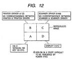
- the additional pattern representing "no correspondence between printer driver and printer” shown in Fig. 12 is added to the color image data.
- the discrimination information representing that the printer driver corresponding to which device was used is added on.
- the add-on process is performed on each color component of the color image data (i.e., C (cyan), M (magenta), Y (yellow) and K (black) components converted from R, G and B components in the steps S51 and S52).
- C cyan
- M magenta
- Y yellow
- K black
- each of the areas A to D in Figs. 4A to 4C is considered as a unit image, and the add-on process is performed on this unit image.
- Fig. 7, 4 ⁇ 4 pixels represented by an area 301 are the part of each of the areas A to D of the multivalue color image data which has been processed until the step S55 by the printer driver in the personal computer 1.
- the color image data is modulated such that the gradation of these 4 ⁇ 4 pixels increases by ⁇ . Then, in accordance with this, the color image data is modulated such that the gradation of areas 302 and 303 decreases by ⁇ . It should be noted that the total number of the pixels of the areas 302 and 303 is the same as that of the area 301. Other areas in Fig. 7 are not modulated. The 8 ⁇ 4 pixels of the areas 301 to 303 are considered as a unit dot of the additional pattern. According to such the modulation processes, since a density (i.e., gradation) of the image itself does not change, the pattern which is difficult to be perceived by the human eyes can be added on.
- a density i.e., gradation
- Figs. 8 and 9 are views showing examples of add-on lines which are provided in the area (each of areas A to D) represented by the color image data.
- reference numeral 401 denotes the add-on line which has a four-pixel width.
- Reference numerals 401a to 401e denote the unit dots shown in Fig. 7 each having the 8 ⁇ 4 pixels.
- the unit dots 401a to 401e are arranged at a predetermined period d1 (e.g., 128 pixels) in the main-scan direction.
- reference numerals 501 to 510 denote the add-on lines which are arranged at a predetermined period d2 (e.g., 16 pixels) in the sub-scan direction.
- d2 e.g. 16 pixels
- the eight add-on lines 502 to 509 can represent the 32-bit additional information. It should be noted that the add-on lines 501 to 509 represent the same information.
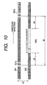
- Fig. 10 and Figs. 11A and 11B are views showing how to express the information (maker and type of scanner 3 and printer 2; product name, version, key ID (serial number) of OS; and the like) by the add-on line.
- reference numerals 501 and 502 denote the add-on lines shown in Fig. 9. These lines are adjacent to each other in the sub-scan direction.
- Reference numerals 501a, 501b (in upper add-on line 501) and 502a (in lower add-on line 502) are unit dots.
- each unit dot is apart from others by at least a distance d3 (e.g., 32 pixels) in the main-scan direction, in order to prevent inconvenience that the unit dots in the upper and lower add-on lines 501 and 502 are close to others in the main-scan direction (i.e., upper-line unit dot is arranged in parallel with lower-line unit dot) and thus these dots become remarkable for the human eyes.
- d3 e.g. 32 pixels
- the data represented by the unit dot is determined by a phase difference between the unit dots 501a and 502a in the main-scan direction. That is, when the lower-line unit dot 502a is added to a position "2" in positions "0" to "F", such the unit dot 502a represents data "2".
- data "0" to “F” can be expressed by a phase aberration amount in the main-scan direction of the upper and lower adjacent add-on lines.
- reference numeral 501 and 502 denote the add-on lines shown in Fig. 9.
- unit dots 74a to 74d are added respectively to the right sides of the unit dots 501a to 501d of the additional patterns which represent the information essentially intended to be added, at a distance d4 (e.g., 16 pixels).
- unit dots 75a to 75d are added respectively to the right sides of unit dots 502a to 502d of the additional patterns which represent the information essentially intended to be added, at a distance d5.
- Such the additional dot acts as a marker for clarifying that each add-on line is which one from the top. Since the markers are to decide the uppermost and lowermost lines in the sub-scan direction from the visibly outputted image, it is enough to add the markers to the two add-on lines.
- the various information to be added is made as the additional pattern formed by the dots.
- the add-on process is not limited to this method. That is, an actual character (i.e., maker name or the like) may be added to the Y component of the C, M, Y and K components which form each of the areas A to D of the reproduced image shown in Figs. 4A to 4C.
- the present invention is not limited to this case, and can be applied to suppress or restrain division of the color image data.
- a bit plane of lower one bit may be replaced by a bit plane in which the various information is represented as the binary image.
- the above add-on process is the add-on process to the multivalue image data.
- the add-on process can be performed on the bit plane of the Y component in the known method of, e.g., shifting the dot positions in each line of the image, in the same manner as that for the multivalue image data.
- the personal computer 1 When the personal computer 1 has a network board instead of the modem 5, the personal computer 1 is connected to the network and thus can perform the image data communicating. Further, in the modem 5 or the network board, an inherent number of the modem 5 or the network board can be added to the image represented by the color image data, in the same manner as that for the other apparatus. Therefore, for example, when the color image data inputted from the scanner 3 is transmitted to other external apparatuses through the network, the inherent discrimination information concerning the scanner 3, the personal computer 1 and the network board is surely added to the color image data to be transmitted.
- the color image data in the case where the color image data is transmitted to the other external apparatus through the network, when such the color image data is made to have the file format in which the color profiled can be embedded, the color profile corresponding to the various apparatuses are transferred to the other external apparatus together with the color image data. Therefore, the apparatus which received the color image data can add the inherent discrimination information concerning the scanner 3, the display 4 and the like to the color image data as the additional pattern on the basis of the received color profile.
- the discrimination information concerning the OS, the printer 2, the scanner 3 and the display 4 is added on to the color image data inputted from the scanner 3.
- the inherent discrimination information of the scanner 3 stored in the OS or the scanner driver is added to the color image data as the additional pattern as soon as the color image data is inputted from the scanner 3, whereby the discrimination information can be surely added on.
- the discrimination information of each apparatus is added on as the additional pattern whenever each apparatus processes the color image data, whereby the discrimination information can be surely added on.
- each device driver for operating each device may add on the discrimination information of the OS, the printer 2, the scanner 3 and the display 4.
- the OS of the personal computer 1 may control the add-on process of each device. Moreover, the OS of the personal computer 1 may confirm the connected devices which are usually confirmed by each device driver.
- an embodiment may include a case where another input apparatus (digital camera, video camera or the like) for inputting the color image data is used instead of the scanner 3.
- the information concerning maker and type of such the input apparatus is added on to the area C shown in Figs. 4A to 4C.
- the present invention is not limited to the apparatuses and the methods for realizing the above-described embodiment.
- program codes of a software to realize the functions of the above-described embodiment are supplied to a computer in an apparatus or a system connected to various devices so as to make the devices operative in order to realize the functions of the above-described embodiment and the various devices are operated in accordance with the programs stored in the computer (CPU or MPU) of the system or apparatus.
- the program codes themselves of the software realize the functions of the above-described embodiment and the program codes themselves carried on means for supplying the program codes to the computer, e.g., a storage medium in which the program codes have been stored, constitute an embodiment of the present invention.
- the memory medium to store the program codes e.g., it is possible to use a floppy disk, a hard disk, an optical disk, an optomagnetic disk, a CD-ROM, a magnetic tape, a nonvolatile memory card, a ROM or the like can be used.
- program codes are included in the embodiment of the present invention even in not only a case where the functions of the above-described embodiment are realized by executing the supplied program codes with the computer but also a case where the functions of the above-described embodiment are realized in cooperation with the OS by which the program codes operate in the computer or another application software or the like.
- an embodiment comprises the supplied program codes stored into a memory provided in a function expansion board of the computer or a function expansion unit connected to the computer so that the CPU or the like provided in the function expansion board or the function expansion unit executes a part or all of the actual processes on the basis of instructions of the program codes, and the functions of the above-described embodiment are realized by the processes.
- the image data when the image data is managed among the plural image processing apparatuses, it can be suppressed or restrained as much as possible that such the image data is illegally or unfairly used. Further, in addition to the conventional additional information, the further effective additional information can be added in the state difficult to be perceived by the human eyes.
- the image data representing the image when the image data representing the image is outputted to the external apparatus, it can be suppressed that such the image data is illegally or unfairly used. Further, when the image data is inputted from the image pickup apparatus capable of reading the image and generating the image data, it can be suppressed that such the image data is illegally or unfairly used.
- the conventional information for identifying the apparatus itself is not added but the another additional information is added, whereby the illegal or unfair use of the image data can be suppressed more effectively.
Landscapes
- Engineering & Computer Science (AREA)
- Toxicology (AREA)
- Physics & Mathematics (AREA)
- Computer Security & Cryptography (AREA)
- Multimedia (AREA)
- Signal Processing (AREA)
- Health & Medical Sciences (AREA)
- General Physics & Mathematics (AREA)
- General Health & Medical Sciences (AREA)
- Editing Of Facsimile Originals (AREA)
- Image Processing (AREA)
- Processing Or Creating Images (AREA)
- Ultra Sonic Daignosis Equipment (AREA)
- Storage Device Security (AREA)
- Facsimile Image Signal Circuits (AREA)
- Color Image Communication Systems (AREA)
Abstract
Description
- The present invention relates to image processing to embed information into an image.
- Conventionally, various technique has been developed to suppress that a negotiable paper such as a bank note or the like is forged by using a single-body image copy machine such as a color copy machine or the like to be unfairly used.
- For example, in one technique, additional information (e.g., machine number of copy machine) is added to an image which is copied and produced by such the color copy machine, in a state that the additional information is difficult to be perceived by human eyes. That is, since the additional information is patternized and then added to only an yellow component of the color image to be copied and produced, such the information becomes difficult to be perceived by the human eyes.
- Thus, when the illegally or unfairly formed image is found, it can be detected by which copy machine (i.e., image formation unit) such the image was copied, by analyzing the additional information added to the image.
- On the other hand, in addition to the problem of negotiable paper, there is some fear that a copyright, a likeness right, a trademark right or the like is infringed or trespassed even on an image such as a picture, a photograph, a video, an animation character or the like. In such a case, the above technique is also effective.
- Further, in recent years, functions of a computer system and peripheral apparatuses for inputting and outputting image data, such as a scanner, a printer and the like have improved year by year. Therefore, in a case where image forming is performed by using such the plural image processing apparatuses, the high-quality image such as the negotiable paper or the like can be formed.
- Furthermore, since network technique such as an internet or the like has progressed, the image data can be transferred from one image processing apparatus to the another distant image processing apparatus.
- Under these circumstances, in order to prevent such illegal actions, it is insufficient that the image processing apparatus for adding the additional information only adds the additional information to specify of identify this image processing apparatus itself. This is because the plural image processing apparatuses which participated in the illegal actions can not be specified or identified only by such the additional information.
- Furthermore, the information for specifying the apparatus itself, such as the machine number, a type number or the like, has been conventionally used as the above additional information.
- EP-A-0637165 discloses an image processing system capable of proving that identification information is added to a print by providing a function for detecting whether a printer has a function for adding the identification information to a printed matter when transferring image data from an electronic apparatus which processes the image data to the printer. The system enables to prevent illegal colour copying of banknotes or the like.
- The present invention provides a computer image processing apparatus as set out in
claim 1. - The present invention also provides a method of processing image data as set out in claim 7.
- The present invention further provides a computer program product as set out in claim 13.
- Optional features are set out in
claims 2 to 6, 8 to 12 and 14. - Embodiments of the invention will now be described with reference to the accompanying drawings, in which:
- Fig. 1 is a block diagram showing an entire image process system used in a present embodiment;
- Fig. 2 is a detailed block diagram for explaining structure of Fig. 1;
- Fig. 3 is a view showing an original image which is read and inputted by a scanner in the present embodiment;
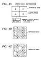
- Figs. 4A, 4B and 4C are views showing a concept of a reproduction image formed in the present embodiment;
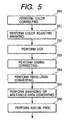
- Fig. 5 is a flow chart showing a series of processes by a printer driver;
- Fig. 6 is a view showing an example of a description form of a color profile;
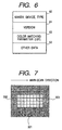
- Fig. 7 is a view showing an additional pattern generation method used in an add-on process;
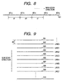
- Fig. 8 is a view showing one add-on line existing in each of areas A to D in Figs. 4A to 4C;
- Fig. 9 is a view showing plural add-on lines existing in each of the areas A to D in Figs. 4A to 4C;
- Fig. 10 is a detailed view showing two of the plural add-on lines in Fig. 9;
- Figs. 11A and 11B are detailed views showing a case where the two add-on lines in Fig. 10 are actually used; and
- Fig. 12 is a view showing a concept of the reproduction image formed in the present embodiment.
-
- Fig. 1 is a block diagram showing an entire image process system which is used in the present embodiment.
- In Fig. 1,
reference numeral 1 denotes a personal computer.Reference numeral 2 denotes a color printer which outputs image data image-processed by thepersonal computer 1, as a visible image.Reference numeral 3 denotes a color scanner which reads R (red), G (green) and B (blue) components of an original image and then outputs color image data to thepersonal computer 1.Reference numeral 4 denotes a display which displays the image data image-processed by thepersonal computer 1, as the visible image.Reference numeral 5 denotes a modem which is provided within thepersonal computer 1. Themodem 5 can output the image data image-processed by thepersonal computer 1 to acommunication line 6 to transmit it to an another external apparatus connected on thecommunication line 6. Further, themodem 5 can receive image data from the another external apparatus, and output the received image data to thedisplay 4 or theprinter 2 to output it visibly. - The above external apparatus may be the image process system shown in Fig. 1, or may be a mere network printer, a network scanner, a network display or the like.
- The
personal computer 1 has a RAM (random-access memory) for storing therein various softwares, and a CPU (central processing unit) for actually initializing the software to perform controlling of the entirepersonal computer 1, including controlling of the image process. - It should be noted that the
printer 2, thescanner 3 and thedisplay 4 have been respectively registered as devices in an OS (operating system) installed in thepersonal computer 1. Further, as shown in Fig. 1, it is assumed that theprinter 2, thescanner 3 and thedisplay 4 are connected to thepersonal computer 1 through connection lines capable of managing the image data and a control command. - All of the
personal computer 1, theprinter 2, thescanner 3 and thedisplay 4 are currently in a power-on state and in a job-waiting state. - Hereinafter, it will be explained a series of processes, i.e., (1) the image data is inputted from the
scanner 3, (2) the inputted image data is edited by using thepersonal computer 1 and thedisplay 4, and (3) the edited image data is outputted as the image by theprinter 2. - A user initializes an commercially available image handling application software which has been installed. Thus, the
scanner 3 is operated through a scanner driver/OS, and the image data generated by reading the original with thescanner 3 is inputted to thepersonal computer 3. - In case of operating the
scanner 3, the scanner driver confirms whether or not the device (i.e., scanner 3 (maker: B, type: 456) in this case) connected to thepersonal computer 1 corresponds to the scanner driver, by performing negotiation between thepersonal computer 1 and thescanner 3 through an interface cable (e.g., IEEE 1284 standard) connecting thepersonal computer 1 and thescanner 3 to each other. Concretely, the scanner driver confirms whether or not maker name, device name, type and the like stored in a color profile included in the scanner driver respectively correspond to maker name, device name, type and the like of the device (i.e., scanner 3) obtained by the negotiation. - If the confirmation results "no correspondence", it is confirmed that a color characteristic (i.e., correction parameter) corresponding to the color profile is different from a color characteristic of the
scanner 3, whereby color matching can not be realized by color correcting (described later). Therefore, the scanner driver gives the user warning by indicating such a fact, through a GUI of the driver. - The user selects change or no change of the scanner driver on the basis of this warning displayed on the
display 4. - When changing the scanner driver, it is performed a process for again confirming the device name and the like of the changed driver and the device name and the like obtained by the negotiation.
- When not changing the scanner driver irrespective of no correspondence between the scanner driver and the
scanner 3, the scanner driver generates information representing "no correspondence between scanner driver and scanner". This information is used in an add-on process (described later). - On the other hand, if the confirmation results "correspondence", the scanner driver does not give such the warning and continues the operation.
- Then, the scanner driver converts the image data generated by reading the original, into the image data of file format such as TIFF, Flash-Pix or the like, embeds an ICC-standard color profile corresponding to the
scanner 3, and stores the color profile in a storage means such as a hard disk or the like in thepersonal computer 1. - Subsequently, the user initiates an image edit application software, calls the file formed in the above process (1) from the application, and causes the
display 4 to display the image. - At this time, the color correction process is performed by using the embeded ICC-standard color profile corresponding to the
scanner 3 as a source profile and the embeded ICC-standard color profile corresponding to thedisplay 4 as a destination profile, to perform matching between a color of the original and a color of the displayed image. - Then, on the basis of the displayed image, the user performs the edit to write a message into the image represented by the image data in the file, lay out plural duplicated images in one file, and the like, so as to change the image data. After then, the image data is again stored with the same file format.
- Further, the user initiates the image edit application software used in the image process system (2), calls the edited image data in the file, outputs the called image data to the
printer 2, and causes theprinter 2 to visibly output an image represented by the image data. - In order to cause the
printer 2 to perform the visible outputting on the basis of the image edit application software, the image data is outputted to theprinter 2 through the printer driver/OS to perform the image forming, in the same manner as in the case where the image handling application software in the process (1) causes thescanner 3 to perform the image data inputting. - Also, in case of operating the
printer 2, the printer driver performs the color correcting (i.e., color matching process) by using the ICC-standard color profile. When the image forming is performed by this image process system, the color correcting is performed by using the color profile of the scanner 3 (having identification number B-456 (maker: B, type: 456)) as the source profile and the color profile of the printer 2 (having identification number A-123) as the destination profile. - Further, in the same manner as in case of operating the
scanner 3, when theprinter 2 performs the visible outputting, it is confirmed whether or not the color profile of the printer driver corresponds (or conforms) to the maker and type of theprinter 2 which is actually connected to thepersonal computer 1. - In addition to such the color correcting, the printer driver performs gamma correcting, color adjusting (i.e., masking process), UCR (under color removal) process, changing of resolution, binarizing process or n-value data generation process corresponding to a print device (i.e., print head such as inkjet head, thermal transfer head or the like) of the printer, and the like, so as to shift or change the color as desired by the user.
- Further, in the image process system in this embodiment, on the image which was formed based on the image data obtained through the binarizing process or the n-value data generation process, an additional pattern for discriminating the image is added on (i.e., add-on) in a conventional known method in the state that the pattern is difficult to be perceived by the human eyes. The representative method for an add-on process will be explained later.
- Subsequently, the software process by the printer driver will be explained with reference to Fig. 5.
- In a step S50 of Fig. 5, the color correction process (i.e., color matching process) is performed on the basis of the color profile of the
scanner 3 and the color profile of theprinter 2. - Subsequently, in a step S51, the color-corrected image data is subjected to the masking process. In steps S52 and S53, the obtained image data is subjected to the UCR process and then to the gamma correction process, respectively. Further, in a step S54, the resolution changing process is performed according to necessity. It should be noted that the resolution changing process in the step S54 may be performed before the processes in the steps S50 to S53 are performed.
- Subsequently, in a step S55, the multivalue color image data is subjected to the binarization process or the n-value data generation process in correspondence with the function of the
printer 2. After the processes in the steps S50 to S55 terminated, in a step S56, the add-on process is performed to add the additional pattern to the binary or n-value color image data. - Such the additional pattern to be added represents the maker and type of the
scanner 3 which inputted the color image data to be image-formed and the maker and type of theprinter 2 which actually formed the color image represented by this color image data, and is being stored in each corresponding color profile. - Further, an additional pattern which is obtained from the information representing product name, version, key ID (i.e., serial number) and the like of the OS (operating system) being initialized by the printer driver is also subjected to the add-on process. It should be noted that the version and the serial number of this OS can be easily obtained by using a system function (so-called command).
- As explained in the process (1), when not changing the scanner driver irrespective of no correspondence between the scanner driver and the
scanner 3, as shown in a conceptional view of Fig. 12, the information representing "no correspondence between scanner driver and scanner" and further discrimination information of the selected scanner driver are added on. In Fig. 12, it should be noted that actually the information is being added on such that this information is difficult to be perceived by the human eyes. - In the add-on process, the information represented by the additional pattern may be added on in the state being difficult to be perceived by the human eyes, after such the information was encoded or enciphered. As a concrete add-on method, e.g., it is supposed that bit data, bar code or the like being the additional pattern is once converted into a spatial frequency component by orthogonal transformation and then added on.
- A conception in case of performing the add-on process is shown in Figs. 3 and 4A to 4C.
- It is assumed that an image shown in Fig. 3 is the original, e.g., a picture which is read by the
scanner 3. Further, it is assumed that the original is read by thescanner 3, the read image is edited by thepersonal computer 1 as being displayed on thedisplay 4, and then the reproduced image is visibly outputted from theprinter 3. - When the visible output process is performed, the OS name, the version and the key ID of the
personal computer 1 are added on to a lower left area A; the maker name (or product name) and the type of theprinter 2 are added on to an upper left area B; the maker name (or product name) and the type of thescanner 3 are added on to an upper right area C; and the maker name (or product name) and the type of thedisplay 4 are added on to a lower right area D, in the state being difficult to be perceived by the human eyes, as shown in the reproduced image of Fig. 4A. - It should be noted that add-on positions are not limited to those shown in Fig. 4A and may be appropriately designed in accordance with necessity. For example, as shown in Fig. 4B, the areas A to D of Fig. 4A may be periodically arranged. Further, when the add-on process is performed without using the
display 4 corresponding to the area D, or when such thedisplay 4 does not exist in the image process system, the reproduced image has the area arrangement shown in Fig. 4C. - In the image process system, when the image data or the image represented by the image data is used for some illegal (i.e., prohibited) action, pursuit can be performed on the basis of the additional pattern added on to this image data or this image.
- Further, a condition for the add-on process may be changed not only in case of performing the visible output process but also in case of performing the image edit process, the image display process or the like. In the present embodiment, when the image data is visibly outputted to the
printer 2, the add-on process is performed in the final step of the image editing. Thus, it can be prevented that the image is edited and changed after the add-on process was performed. - The color profile used in the present embodiment is to correct a color characteristic which is inherent in the device (
printer 2,scanner 3,display 4 or the like). Therefore, the color profile corresponds to each device and is generally provided from each device maker. - Fig. 6 is a view showing a data format of above-described color profile.
- In Fig. 6, ID information which represents the maker, the device name, the type and the like of the device corresponding to this color profile is described in an
area 60, version information of the color profile of this device is described in anarea 61, and a look-up table is described in anarea 62 as a color matching parameter used in the color correcting. - Further, other data is stored in an
area 63. For example, an additional pattern or the like which is used to add on the maker, the device name, the version and the like in the add-on process is described in thearea 63. - In a case where the additional pattern is not described, it is necessary for the OS or the various devices themselves to have the function for converting the maker, the device name, the version and the like into the additional pattern.
- In the present embodiment, the example is shown in which the ICC-standard color profile is used. However, even in case of a dedicated driver not using the ICC-standard color profile, similarly, the correspondence or matching between the printer driver and the device (i.e., printer) may be confirmed by performing the negotiation between the personal computer 1 (i.e., host computer) and the device. If such the confirmation results no correspondence between the printer driver and the printer, the additional pattern representing "no correspondence between printer driver and printer" shown in Fig. 12 is added to the color image data. Moreover, the discrimination information representing that the printer driver corresponding to which device was used is added on.
- As described above, even if the device driver and the device are not corresponding to each other, it is at least possible that the serial number of the OS is added on.
- Hereinafter, one example of the concrete add-on process in the present embodiment will be explained.
- It is assumed that the following example is directed to the case where the multivalue data generating (eight-bit data generating on each color = 256 gradation generating) is performed because the printer to be used is a multivalue printer in the step S55 of Fig. 5, i.e., the add-on process in the step S56 is performed on the multivalue color image data.
- It should be noted that the add-on process is performed on each color component of the color image data (i.e., C (cyan), M (magenta), Y (yellow) and K (black) components converted from R, G and B components in the steps S51 and S52). In the present embodiment, it is assumed that the add-on process is performed only on the Y component, and thus such a case will be explained.
- It is further assumed that each of the areas A to D in Figs. 4A to 4C is considered as a unit image, and the add-on process is performed on this unit image.
- In Fig. 7, 4 × 4 pixels represented by an
area 301 are the part of each of the areas A to D of the multivalue color image data which has been processed until the step S55 by the printer driver in thepersonal computer 1. - The color image data is modulated such that the gradation of these 4 × 4 pixels increases by α. Then, in accordance with this, the color image data is modulated such that the gradation of
areas areas area 301. Other areas in Fig. 7 are not modulated. The 8 × 4 pixels of theareas 301 to 303 are considered as a unit dot of the additional pattern. According to such the modulation processes, since a density (i.e., gradation) of the image itself does not change, the pattern which is difficult to be perceived by the human eyes can be added on. - Figs. 8 and 9 are views showing examples of add-on lines which are provided in the area (each of areas A to D) represented by the color image data.
- In Fig. 8,
reference numeral 401 denotes the add-on line which has a four-pixel width.Reference numerals 401a to 401e denote the unit dots shown in Fig. 7 each having the 8 × 4 pixels. Theunit dots 401a to 401e are arranged at a predetermined period d1 (e.g., 128 pixels) in the main-scan direction. - Further, in Fig. 9,
reference numerals 501 to 510 denote the add-on lines which are arranged at a predetermined period d2 (e.g., 16 pixels) in the sub-scan direction. Although the details will be described later, e.g., since one add-on line can represent the four-bit information, the eight add-onlines 502 to 509 (as eight-tuple) can represent the 32-bit additional information. It should be noted that the add-onlines 501 to 509 represent the same information. - Fig. 10 and Figs. 11A and 11B are views showing how to express the information (maker and type of
scanner 3 andprinter 2; product name, version, key ID (serial number) of OS; and the like) by the add-on line. - In Fig. 10,
reference numerals Reference numerals adjacent lines lines - The data represented by the unit dot is determined by a phase difference between the
unit dots line unit dot 502a is added to a position "2" in positions "0" to "F", such theunit dot 502a represents data "2". - In other words, data "0" to "F" can be expressed by a phase aberration amount in the main-scan direction of the upper and lower adjacent add-on lines.
- In Figs. 11A and 11B,
reference numeral line 502,unit dots 74a to 74d are added respectively to the right sides of theunit dots 501a to 501d of the additional patterns which represent the information essentially intended to be added, at a distance d4 (e.g., 16 pixels). Similarly, in the add-online 502,unit dots 75a to 75d are added respectively to the right sides ofunit dots 502a to 502d of the additional patterns which represent the information essentially intended to be added, at a distance d5. Such the additional dot acts as a marker for clarifying that each add-on line is which one from the top. Since the markers are to decide the uppermost and lowermost lines in the sub-scan direction from the visibly outputted image, it is enough to add the markers to the two add-on lines. - Since the above add-on process is performed on the Y component in the Y, M, C and K components, it is difficult for the human eyes to discriminate it.
- In the above add-on process, the various information to be added is made as the additional pattern formed by the dots. The add-on process is not limited to this method. That is, an actual character (i.e., maker name or the like) may be added to the Y component of the C, M, Y and K components which form each of the areas A to D of the reproduced image shown in Figs. 4A to 4C.
- Further, it is described in the present embodiment the case where the color image data is visibly outputted by the
printer 2. However, the present invention is not limited to this case, and can be applied to suppress or restrain division of the color image data. In such a case, since the various information may not be discriminated from the visibly outputted image, e.g., when the multivalue image data is managed, a bit plane of lower one bit may be replaced by a bit plane in which the various information is represented as the binary image. By such a method, quality of the color image data itself is hardly deteriorated. - The above add-on process is the add-on process to the multivalue image data. However, even in case of performing the add-on process to the binary image data, the add-on process can be performed on the bit plane of the Y component in the known method of, e.g., shifting the dot positions in each line of the image, in the same manner as that for the multivalue image data.
- When the
personal computer 1 has a network board instead of themodem 5, thepersonal computer 1 is connected to the network and thus can perform the image data communicating. Further, in themodem 5 or the network board, an inherent number of themodem 5 or the network board can be added to the image represented by the color image data, in the same manner as that for the other apparatus. Therefore, for example, when the color image data inputted from thescanner 3 is transmitted to other external apparatuses through the network, the inherent discrimination information concerning thescanner 3, thepersonal computer 1 and the network board is surely added to the color image data to be transmitted. - Further, in the present embodiment, in the case where the color image data is transmitted to the other external apparatus through the network, when such the color image data is made to have the file format in which the color profiled can be embedded, the color profile corresponding to the various apparatuses are transferred to the other external apparatus together with the color image data. Therefore, the apparatus which received the color image data can add the inherent discrimination information concerning the
scanner 3, thedisplay 4 and the like to the color image data as the additional pattern on the basis of the received color profile. - In the present embodiment, when the color image data to which the color profile was added is outputted to the
printer 2, the discrimination information concerning the OS, theprinter 2, thescanner 3 and thedisplay 4 is added on to the color image data inputted from thescanner 3. However, in order to prevent the inconvenience that the color image data is unfairly or illegally used before it is outputted to theprinter 2, the inherent discrimination information of thescanner 3 stored in the OS or the scanner driver is added to the color image data as the additional pattern as soon as the color image data is inputted from thescanner 3, whereby the discrimination information can be surely added on. - Similarly, for all the apparatuses, the discrimination information of each apparatus is added on as the additional pattern whenever each apparatus processes the color image data, whereby the discrimination information can be surely added on.
- In this case, since it is difficult for the printer driver to perform the add-on process, each device driver for operating each device may add on the discrimination information of the OS, the
printer 2, thescanner 3 and thedisplay 4. - In another method, the OS of the
personal computer 1 may control the add-on process of each device. Moreover, the OS of thepersonal computer 1 may confirm the connected devices which are usually confirmed by each device driver. - It should be noted that an embodiment may include a case where another input apparatus (digital camera, video camera or the like) for inputting the color image data is used instead of the
scanner 3. In this case, the information concerning maker and type of such the input apparatus is added on to the area C shown in Figs. 4A to 4C. - The present invention is not limited to the apparatuses and the methods for realizing the above-described embodiment.
- In an embodiment, program codes of a software to realize the functions of the above-described embodiment are supplied to a computer in an apparatus or a system connected to various devices so as to make the devices operative in order to realize the functions of the above-described embodiment and the various devices are operated in accordance with the programs stored in the computer (CPU or MPU) of the system or apparatus.
- In such a case, the program codes themselves of the software realize the functions of the above-described embodiment and the program codes themselves carried on means for supplying the program codes to the computer, e.g., a storage medium in which the program codes have been stored, constitute an embodiment of the present invention.
- As such the memory medium to store the program codes, e.g., it is possible to use a floppy disk, a hard disk, an optical disk, an optomagnetic disk, a CD-ROM, a magnetic tape, a nonvolatile memory card, a ROM or the like can be used.
- It will be obviously understood that the program codes are included in the embodiment of the present invention even in not only a case where the functions of the above-described embodiment are realized by executing the supplied program codes with the computer but also a case where the functions of the above-described embodiment are realized in cooperation with the OS by which the program codes operate in the computer or another application software or the like.
- Further, it will be also obviously understood that an embodiment comprises the supplied program codes stored into a memory provided in a function expansion board of the computer or a function expansion unit connected to the computer so that the CPU or the like provided in the function expansion board or the function expansion unit executes a part or all of the actual processes on the basis of instructions of the program codes, and the functions of the above-described embodiment are realized by the processes.
- According to the above-described embodiments of the present invention, when the image data is managed among the plural image processing apparatuses, it can be suppressed or restrained as much as possible that such the image data is illegally or unfairly used. Further, in addition to the conventional additional information, the further effective additional information can be added in the state difficult to be perceived by the human eyes.
- Concretely, when the image data representing the image is outputted to the external apparatus, it can be suppressed that such the image data is illegally or unfairly used. Further, when the image data is inputted from the image pickup apparatus capable of reading the image and generating the image data, it can be suppressed that such the image data is illegally or unfairly used.
- Furthermore, on the input image data, the conventional information for identifying the apparatus itself is not added but the another additional information is added, whereby the illegal or unfair use of the image data can be suppressed more effectively.
Claims (14)
- A computer image processing apparatus (1) connectable to a plurality of different separate peripheral apparatus (2, 3, 4) for the transfer of image data therebetween, comprising:characterised by:means for processing image data;means for causing the apparatus to communicate with a peripheral apparatus for the transfer of image data therebetween to determine the identity of the peripheral apparatus; andadding means for adding additional information to the image data conveying the identity of the peripheral apparatus in a form such that the identification information is difficult to see with the naked human eye when an image is realised from the image data.
- An apparatus according to claim 1, wherein the apparatus is connectable to a plurality of different separate peripheral apparatus for the receipt of image data therefrom, and wherein the adding means is arranged to add additional information to image data received from a peripheral apparatus conveying the identity of the peripheral apparatus from which the image data was received.
- An apparatus according to claim 1 or claim 2, wherein the apparatus is connectable to a plurality of different separate image forming peripheral apparatus for the output of image data thereto, and wherein the adding means is arranged to add additional information to image data to be output to an image forming peripheral apparatus conveying the identity of the peripheral apparatus to which the image data is to be output.
- An apparatus according to any preceding claim, wherein the apparatus is connectable to a plurality of different separate peripheral apparatus for the receipt of image data therefrom and to a plurality of different separate image forming peripheral apparatus for the output of image data thereto, and wherein the adding means is arranged to add the additional information to convey the identity of the peripheral apparatus from which the image data was received and also the identity of the image forming peripheral apparatus to which the image data is to be output.
- An apparatus according to any preceding claim, wherein the adding means is arranged to add the additional information to convey the identity of the peripheral apparatus and also the identity of the computer image processing apparatus itself.
- An apparatus according to claim 5, wherein the computer image processing apparatus is arranged to operate under the control of operating system software, and wherein the adding means is arranged to add the additional information to convey the identity of the computer image processing apparatus by adding additional information conveying the identity of the operating system software.
- A method of processing image data in a computer image processing apparatus connected to at least one of a plurality of different separate peripheral apparatus for the transfer of image data therebetween, the method comprising:characterised by:processing image data;causing the apparatus to communicate with a peripheral apparatus for the transfer of image data therebetween to determine the identity of the peripheral apparatus; andadding additional information to the image data conveying the identity of the peripheral apparatus in a form such that the identification information is difficult to see with the naked human eye when an image is realised from the image data.
- A method according to claim 7, wherein the computer image processing apparatus is connected to at least one of a plurality of different separate peripheral apparatus for the receipt of image data therefrom, and wherein the process of adding the additional information comprises adding additional information to image data received from a peripheral apparatus conveying the identity of the peripheral apparatus from which the image data was received.
- A method according to claim 7 or claim 8, wherein the computer image processing apparatus is connected to at least one of a plurality of different separate image forming peripheral apparatus for the output of image data thereto, and wherein the process of adding the additional information comprises adding additional information to image data to be output to an image forming peripheral apparatus conveying the identity of the peripheral apparatus to which the image data is to be output.
- A method according to any of claims 7 to 9, wherein the computer image processing apparatus is connected to at least one of a plurality of different separate peripheral apparatus for the receipt of image data therefrom and also to at least one of a plurality of different separate image forming peripheral apparatus for the output of image data thereto, and wherein the process of adding the additional information comprises adding additional information to convey the identity of the peripheral apparatus from which the image data was received and also the identity of the image forming peripheral apparatus to which the image data is to be output.
- A method according to any of claims 7 to 10, wherein the process of adding the additional information comprises adding additional information to convey the identity of the peripheral apparatus and also the identity of the computer image processing apparatus itself.
- A method according to claim 11, wherein the computer image processing apparatus is arranged to operate under the control of operating system software, and wherein the process of adding the additional information comprises adding additional information to convey the identity of the computer image processing apparatus by adding additional information conveying the identity of the operating system software.
- A computer program product comprising a carrier carrying instructions to program a programmable processing apparatus to become operable to perform a method as set out in at least one of claims 7 to 12.
- A computer program product according to claim 13, when embodied as a storage medium storing the instructions.
Applications Claiming Priority (3)
| Application Number | Priority Date | Filing Date | Title |
|---|---|---|---|
| JP304708/96 | 1996-11-15 | ||
| JP30470896 | 1996-11-15 | ||
| JP8304708A JPH10145584A (en) | 1996-11-15 | 1996-11-15 | Image processing apparatus and method and storage medium storing method |
Publications (3)
| Publication Number | Publication Date |
|---|---|
| EP0843237A2 EP0843237A2 (en) | 1998-05-20 |
| EP0843237A3 EP0843237A3 (en) | 1998-11-18 |
| EP0843237B1 true EP0843237B1 (en) | 2004-05-06 |
Family
ID=17936263
Family Applications (1)
| Application Number | Title | Priority Date | Filing Date |
|---|---|---|---|
| EP97308919A Expired - Lifetime EP0843237B1 (en) | 1996-11-15 | 1997-11-06 | Image processing apparatus, image processing method and storage medium |
Country Status (5)
| Country | Link |
|---|---|
| US (1) | US6546129B1 (en) |
| EP (1) | EP0843237B1 (en) |
| JP (1) | JPH10145584A (en) |
| AT (1) | ATE266218T1 (en) |
| DE (1) | DE69728949T2 (en) |
Families Citing this family (17)
| Publication number | Priority date | Publication date | Assignee | Title |
|---|---|---|---|---|
| JP2000050054A (en) | 1998-07-31 | 2000-02-18 | Canon Inc | Recording system |
| EP1043883B1 (en) * | 1999-04-06 | 2011-07-27 | Canon Kabushiki Kaisha | Scanner, printer, memory medium and image processing method |
| US6947994B1 (en) * | 1999-04-09 | 2005-09-20 | Canon Kabushiki Kaisha | Negotiating an exchange of image processing functionality |
| US7006257B1 (en) * | 1999-11-19 | 2006-02-28 | Canon Kabushiki Kaisha | Image processing apparatus, image processing method, and storage medium |
| US6671067B1 (en) * | 2000-01-05 | 2003-12-30 | Monaco Systems, Inc. | Scanner and printer profiling system |
| JP2002019221A (en) * | 2000-07-03 | 2002-01-23 | Canon Inc | Image forming apparatus and method |
| JP2002077605A (en) * | 2000-08-31 | 2002-03-15 | Omron Corp | Image processing device and recording medium |
| US20020180997A1 (en) * | 2001-05-29 | 2002-12-05 | Imation Corp. | Embedding color profiles in raster image data using data hiding techniques |
| CN100338627C (en) * | 2002-06-04 | 2007-09-19 | 佳能株式会社 | Image processing apparatus and its controlling method and image proessing system |
| JP4655538B2 (en) * | 2004-08-06 | 2011-03-23 | ヤマハ株式会社 | Electronic music apparatus and program |
| DE102006002886A1 (en) | 2006-01-20 | 2007-07-26 | Oce Printing Systems Gmbh | Producing and processing method for document data stream involves assigning indexed color management resource to document data stream, with which color based data of document data stream are assigned to given color palette |
| TWI328780B (en) * | 2006-12-19 | 2010-08-11 | Hiti Digital Inc | Image data processing system and method thereof |
| JP4767203B2 (en) * | 2007-03-16 | 2011-09-07 | 株式会社リコー | Image processing apparatus, image processing method, computer program, and storage medium |
| JP2009141700A (en) | 2007-12-06 | 2009-06-25 | Ricoh Co Ltd | Image processing apparatus, image processing method, image processing program, and recording medium |
| JP5564834B2 (en) * | 2009-06-09 | 2014-08-06 | 大日本印刷株式会社 | Image processing apparatus and display apparatus |
| CN104916033B (en) * | 2015-05-28 | 2017-11-10 | 浪潮软件集团有限公司 | Bill information analysis method based on bank bill acceptance machine (CTM) |
| CN108091033B (en) * | 2017-12-26 | 2020-10-20 | 深圳怡化电脑股份有限公司 | Paper money identification method and device, terminal equipment and storage medium |
Family Cites Families (14)
| Publication number | Priority date | Publication date | Assignee | Title |
|---|---|---|---|---|
| JP2522537B2 (en) | 1989-01-31 | 1996-08-07 | 株式会社テック | Facsimile diagnostic device |
| US5123063A (en) * | 1990-10-10 | 1992-06-16 | Fuji Xero Co., Ltd. | Image processor utilizing and controlling a plurality of scanners |
| US5524933A (en) | 1992-05-29 | 1996-06-11 | Ecole Polytechnique Federale De Lausanne | Method for the marking of documents |
| US5390003A (en) | 1992-11-30 | 1995-02-14 | Minolta Camera Kabushiki Kaisha | Copying system for preventing copying of copy-prohibited images |
| US5291243A (en) * | 1993-02-05 | 1994-03-01 | Xerox Corporation | System for electronically printing plural-color tamper-resistant documents |
| JPH0778251A (en) | 1993-07-22 | 1995-03-20 | Xerox Corp | Verifying method of source |
| US5798844A (en) * | 1993-07-23 | 1998-08-25 | Ricoh Company, Ltd. | Duplicator having function concerning specific mark put on recording sheet and image forming apparatus having function of processing confidential documents |
| US6621922B2 (en) | 1993-07-30 | 2003-09-16 | Canon Kabushiki Kaisha | Image processing system and electronic apparatuses |
| US5610688A (en) | 1993-11-05 | 1997-03-11 | Sharp Kabushiki Kaisha | Image forming apparatus having illegal use prevention |
| WO1995031794A1 (en) | 1994-05-17 | 1995-11-23 | Apple Computers, Inc. | Computer graphics color management system |
| US5606609A (en) * | 1994-09-19 | 1997-02-25 | Scientific-Atlanta | Electronic document verification system and method |
| JP3224480B2 (en) * | 1994-09-30 | 2001-10-29 | キヤノン株式会社 | Color image processing equipment |
| US5568550A (en) * | 1994-10-05 | 1996-10-22 | Shmuel Ur | Method and system for identifying documents generated by an unauthorized software copy |
| US5668636A (en) * | 1995-12-20 | 1997-09-16 | Xerox Corporation | Embedded data controlled digital highlight color copier |
-
1996
- 1996-11-15 JP JP8304708A patent/JPH10145584A/en not_active Withdrawn
-
1997
- 1997-11-04 US US08/963,984 patent/US6546129B1/en not_active Expired - Fee Related
- 1997-11-06 EP EP97308919A patent/EP0843237B1/en not_active Expired - Lifetime
- 1997-11-06 AT AT97308919T patent/ATE266218T1/en not_active IP Right Cessation
- 1997-11-06 DE DE69728949T patent/DE69728949T2/en not_active Expired - Lifetime
Also Published As
| Publication number | Publication date |
|---|---|
| US6546129B1 (en) | 2003-04-08 |
| DE69728949T2 (en) | 2005-04-07 |
| DE69728949D1 (en) | 2004-06-09 |
| ATE266218T1 (en) | 2004-05-15 |
| JPH10145584A (en) | 1998-05-29 |
| EP0843237A2 (en) | 1998-05-20 |
| EP0843237A3 (en) | 1998-11-18 |
Similar Documents
| Publication | Publication Date | Title |
|---|---|---|
| US6546129B1 (en) | Image processing apparatus, method, and medium for adding identification information | |
| EP0551016B1 (en) | Image processing method for adding an identification code to an image | |
| US8687242B2 (en) | Image processing apparatus for obtaining image data comprising a code generation section, an encryption section, a pattern generation section, and an addition section | |
| US6166750A (en) | Image processing apparatus and method for adding predetermined additional information to an image by adding a predetermined number of unit dots to partial color component data of the image | |
| EP1739947B1 (en) | Density determination method, image forming apparatus, and image processing system | |
| US6239818B1 (en) | Printing method and apparatus | |
| JP2003087563A (en) | Image processing apparatus and control method thereof | |
| JP2000175031A (en) | Image processing unit, image processing method and image input device | |
| US8724173B2 (en) | Control apparatus, controlling method, program and recording medium | |
| JPH11220607A (en) | Image processing apparatus, method, and computer-readable storage medium | |
| US7436551B2 (en) | Image processing apparatus, image processing method, and storage medium | |
| US8274708B2 (en) | Image processing apparatus and method for preventing removal of an encoded image | |
| US8427708B2 (en) | Apparatus and method for controlling printing of information embedded in a document | |
| EP1043883B1 (en) | Scanner, printer, memory medium and image processing method | |
| JP7858347B2 (en) | Image processing apparatus, image processing method, and printing apparatus | |
| JP3367959B2 (en) | Image processing apparatus and method | |
| JP3566610B2 (en) | Image processing apparatus and image processing method | |
| JP3247446B2 (en) | Image processing apparatus and image processing method | |
| US20250260776A1 (en) | Image processing apparatus, image processing method, and storage medium | |
| JP2006025170A (en) | Image processing device | |
| US20250260775A1 (en) | Image processing apparatus, image processing method, and storage medium | |
| JP2023130915A (en) | Image processing device, image processing method, and printing device | |
| JPH1132202A (en) | Image processing apparatus and method | |
| JP2000078391A (en) | Printing method and device and recording medium thereof | |
| JP2000078387A (en) | Printing method and device, pattern read method and device and recording medium |
Legal Events
| Date | Code | Title | Description |
|---|---|---|---|
| PUAI | Public reference made under article 153(3) epc to a published international application that has entered the european phase |
Free format text: ORIGINAL CODE: 0009012 |
|
| AK | Designated contracting states |
Kind code of ref document: A2 Designated state(s): AT BE CH DE DK ES FI FR GB GR IE IT LI LU MC NL PT SE |
|
| AX | Request for extension of the european patent |
Free format text: AL;LT;LV;RO;SI |
|
| PUAL | Search report despatched |
Free format text: ORIGINAL CODE: 0009013 |
|
| AK | Designated contracting states |
Kind code of ref document: A3 Designated state(s): AT BE CH DE DK ES FI FR GB GR IE IT LI LU MC NL PT SE |
|
| AX | Request for extension of the european patent |
Free format text: AL;LT;LV;RO;SI |
|
| PUAF | Information related to the publication of a search report (a3 document) modified or deleted |
Free format text: ORIGINAL CODE: 0009199SEPU |
|
| PUAL | Search report despatched |
Free format text: ORIGINAL CODE: 0009013 |
|
| 17P | Request for examination filed |
Effective date: 19990331 |
|
| D17D | Deferred search report published (deleted) | ||
| AX | Request for extension of the european patent |
Free format text: AL;LT;LV;RO;SI |
|
| AKX | Designation fees paid |
Free format text: AT BE CH DE DK ES FI FR GB GR IE IT LI LU MC NL PT SE |
|
| 17Q | First examination report despatched |
Effective date: 20010706 |
|
| GRAP | Despatch of communication of intention to grant a patent |
Free format text: ORIGINAL CODE: EPIDOSNIGR1 |
|
| GRAS | Grant fee paid |
Free format text: ORIGINAL CODE: EPIDOSNIGR3 |
|
| GRAA | (expected) grant |
Free format text: ORIGINAL CODE: 0009210 |
|
| AK | Designated contracting states |
Kind code of ref document: B1 Designated state(s): AT BE CH DE DK ES FI FR GB GR IE IT LI LU MC NL PT SE |
|
| PG25 | Lapsed in a contracting state [announced via postgrant information from national office to epo] |
Ref country code: NL Free format text: LAPSE BECAUSE OF FAILURE TO SUBMIT A TRANSLATION OF THE DESCRIPTION OR TO PAY THE FEE WITHIN THE PRESCRIBED TIME-LIMIT Effective date: 20040506 Ref country code: LI Free format text: LAPSE BECAUSE OF FAILURE TO SUBMIT A TRANSLATION OF THE DESCRIPTION OR TO PAY THE FEE WITHIN THE PRESCRIBED TIME-LIMIT Effective date: 20040506 Ref country code: IT Free format text: LAPSE BECAUSE OF FAILURE TO SUBMIT A TRANSLATION OF THE DESCRIPTION OR TO PAY THE FEE WITHIN THE PRE;WARNING: LAPSES OF ITALIAN PATENTS WITH EFFECTIVE DATE BEFORE 2007 MAY HAVE OCCURRED AT ANY TIME BEFORE 2007. THE CORRECT EFFECTIVE DATE MAY BE DIFFERENT FROM THE ONE RECORDED.SCRIBED TIME-LIMIT Effective date: 20040506 Ref country code: FI Free format text: LAPSE BECAUSE OF FAILURE TO SUBMIT A TRANSLATION OF THE DESCRIPTION OR TO PAY THE FEE WITHIN THE PRESCRIBED TIME-LIMIT Effective date: 20040506 Ref country code: CH Free format text: LAPSE BECAUSE OF FAILURE TO SUBMIT A TRANSLATION OF THE DESCRIPTION OR TO PAY THE FEE WITHIN THE PRESCRIBED TIME-LIMIT Effective date: 20040506 Ref country code: BE Free format text: LAPSE BECAUSE OF FAILURE TO SUBMIT A TRANSLATION OF THE DESCRIPTION OR TO PAY THE FEE WITHIN THE PRESCRIBED TIME-LIMIT Effective date: 20040506 Ref country code: AT Free format text: LAPSE BECAUSE OF FAILURE TO SUBMIT A TRANSLATION OF THE DESCRIPTION OR TO PAY THE FEE WITHIN THE PRESCRIBED TIME-LIMIT Effective date: 20040506 |
|
| REG | Reference to a national code |
Ref country code: GB Ref legal event code: FG4D |
|
| REG | Reference to a national code |
Ref country code: CH Ref legal event code: EP |
|
| REF | Corresponds to: |
Ref document number: 69728949 Country of ref document: DE Date of ref document: 20040609 Kind code of ref document: P |
|
| REG | Reference to a national code |
Ref country code: IE Ref legal event code: FG4D |
|
| PG25 | Lapsed in a contracting state [announced via postgrant information from national office to epo] |
Ref country code: SE Free format text: LAPSE BECAUSE OF FAILURE TO SUBMIT A TRANSLATION OF THE DESCRIPTION OR TO PAY THE FEE WITHIN THE PRESCRIBED TIME-LIMIT Effective date: 20040806 Ref country code: GR Free format text: LAPSE BECAUSE OF FAILURE TO SUBMIT A TRANSLATION OF THE DESCRIPTION OR TO PAY THE FEE WITHIN THE PRESCRIBED TIME-LIMIT Effective date: 20040806 Ref country code: DK Free format text: LAPSE BECAUSE OF FAILURE TO SUBMIT A TRANSLATION OF THE DESCRIPTION OR TO PAY THE FEE WITHIN THE PRESCRIBED TIME-LIMIT Effective date: 20040806 |
|
| PG25 | Lapsed in a contracting state [announced via postgrant information from national office to epo] |
Ref country code: ES Free format text: LAPSE BECAUSE OF FAILURE TO SUBMIT A TRANSLATION OF THE DESCRIPTION OR TO PAY THE FEE WITHIN THE PRESCRIBED TIME-LIMIT Effective date: 20040817 |
|
| NLV1 | Nl: lapsed or annulled due to failure to fulfill the requirements of art. 29p and 29m of the patents act | ||
| PG25 | Lapsed in a contracting state [announced via postgrant information from national office to epo] |
Ref country code: LU Free format text: LAPSE BECAUSE OF NON-PAYMENT OF DUE FEES Effective date: 20041106 |
|
| PG25 | Lapsed in a contracting state [announced via postgrant information from national office to epo] |
Ref country code: IE Free format text: LAPSE BECAUSE OF NON-PAYMENT OF DUE FEES Effective date: 20041108 |
|
| REG | Reference to a national code |
Ref country code: CH Ref legal event code: PL |
|
| PG25 | Lapsed in a contracting state [announced via postgrant information from national office to epo] |
Ref country code: MC Free format text: LAPSE BECAUSE OF NON-PAYMENT OF DUE FEES Effective date: 20041130 |
|
| ET | Fr: translation filed | ||
| PLBE | No opposition filed within time limit |
Free format text: ORIGINAL CODE: 0009261 |
|
| STAA | Information on the status of an ep patent application or granted ep patent |
Free format text: STATUS: NO OPPOSITION FILED WITHIN TIME LIMIT |
|
| 26N | No opposition filed |
Effective date: 20050208 |
|
| REG | Reference to a national code |
Ref country code: IE Ref legal event code: MM4A |
|
| PG25 | Lapsed in a contracting state [announced via postgrant information from national office to epo] |
Ref country code: PT Free format text: LAPSE BECAUSE OF NON-PAYMENT OF DUE FEES Effective date: 20041006 |
|
| PGFP | Annual fee paid to national office [announced via postgrant information from national office to epo] |
Ref country code: DE Payment date: 20131130 Year of fee payment: 17 Ref country code: GB Payment date: 20131119 Year of fee payment: 17 |
|
| PGFP | Annual fee paid to national office [announced via postgrant information from national office to epo] |
Ref country code: FR Payment date: 20131125 Year of fee payment: 17 |
|
| REG | Reference to a national code |
Ref country code: DE Ref legal event code: R119 Ref document number: 69728949 Country of ref document: DE |
|
| GBPC | Gb: european patent ceased through non-payment of renewal fee |
Effective date: 20141106 |
|
| REG | Reference to a national code |
Ref country code: FR Ref legal event code: ST Effective date: 20150731 |
|
| PG25 | Lapsed in a contracting state [announced via postgrant information from national office to epo] |
Ref country code: GB Free format text: LAPSE BECAUSE OF NON-PAYMENT OF DUE FEES Effective date: 20141106 Ref country code: DE Free format text: LAPSE BECAUSE OF NON-PAYMENT OF DUE FEES Effective date: 20150602 |
|
| PG25 | Lapsed in a contracting state [announced via postgrant information from national office to epo] |
Ref country code: FR Free format text: LAPSE BECAUSE OF NON-PAYMENT OF DUE FEES Effective date: 20141201 |