EP0843227A1 - Electrophotographic image forming apparatus - Google Patents
Electrophotographic image forming apparatus Download PDFInfo
- Publication number
- EP0843227A1 EP0843227A1 EP97119175A EP97119175A EP0843227A1 EP 0843227 A1 EP0843227 A1 EP 0843227A1 EP 97119175 A EP97119175 A EP 97119175A EP 97119175 A EP97119175 A EP 97119175A EP 0843227 A1 EP0843227 A1 EP 0843227A1
- Authority
- EP
- European Patent Office
- Prior art keywords
- diameter
- toner particle
- toner
- image carrier
- toner particles
- Prior art date
- Legal status (The legal status is an assumption and is not a legal conclusion. Google has not performed a legal analysis and makes no representation as to the accuracy of the status listed.)
- Granted
Links
Images


Classifications
-
- G—PHYSICS
- G03—PHOTOGRAPHY; CINEMATOGRAPHY; ANALOGOUS TECHNIQUES USING WAVES OTHER THAN OPTICAL WAVES; ELECTROGRAPHY; HOLOGRAPHY
- G03G—ELECTROGRAPHY; ELECTROPHOTOGRAPHY; MAGNETOGRAPHY
- G03G13/00—Electrographic processes using a charge pattern
- G03G13/06—Developing
- G03G13/08—Developing using a solid developer, e.g. powder developer
-
- G—PHYSICS
- G03—PHOTOGRAPHY; CINEMATOGRAPHY; ANALOGOUS TECHNIQUES USING WAVES OTHER THAN OPTICAL WAVES; ELECTROGRAPHY; HOLOGRAPHY
- G03G—ELECTROGRAPHY; ELECTROPHOTOGRAPHY; MAGNETOGRAPHY
- G03G13/00—Electrographic processes using a charge pattern
- G03G13/20—Fixing, e.g. by using heat
Definitions
- the present invention relates to an electrophotographic image forming apparatus such as an electrophotographic printer, and in particular, to a diameter of a toner particle.
- toner particles are attached to the electrostatic latent image in a developing section to form a toner image on the surface of the photosensitive drum. Then, the toner image is transferred onto paper as a transfer material in a transfer section.
- the paper is then fed to a fixing device, and the toner image is fixed on the paper by the fixing device.
- the average diameter of the toner particles is in a range of 5 [ ⁇ m] to 15 [ ⁇ m] and varies within the range of approximately 10 [ ⁇ m].
- the resolution of the electrophotographic printer is determined to be 300 [dpi] or 600 [dpi] in terms of the laser scanner, the LED head or the like, and an electrostatic latent image is to be formed with the resolution of 300 [dpi] or 600 [dpi].
- At least ten toner particles are to be attached to each of irradiated spots constituting the electrostatic latent image during the development.
- the toner particles in order to increase the resolution of the electrophotographic printer to 1200 [dpi], for example, it is necessary to use the toner particles with a diameter of not more than 5 [ ⁇ m]. However, such toner particles tend to float in the air, thus resulting in the pollution of the environment.
- an electrophotographic image forming apparatus has: an image carrier; a charging device for charging a surface of the image carrier; and a light beam scanner for projecting a light beam on the surface of the image carrier, thereby forming irradiated spots constituting an electrostatic latent image on the surface of the image carrier.
- the irradiated spots are formed on intersections of a grid which is composed of a plurality of first lines extending on the surface of the image carrier in a main-scanning direction and arranged at equal first intervals and a plurality of second lines extending on the surface of the image carrier in a sub-scanning direction perpendicular to the main-scanning direction and arranged at equal second intervals.
- the apparatus also has a developing device for attaching a toner particle extending to each of the irradiated spots on the surface of the image carrier to form a toner image on the surface of the image carrier; a transfer device for transferring the toner particle to a transfer material; and a fixing device for fixing the toner particle on the transfer material.
- the developing device contains the toner particles, each diameter of which is determined in such a way that each diameter of fixed toner particles is equal to approximately a length of a diagonal line of the grid.
- each diameter of the toner particles in the developing device is in a range of 0.7 times to 1.0 times as long as the first interval and/or the second interval.
- a method for electrophotographically forming an image comprising the steps of: charging a surface of a image carrier; projecting a light beam on the surface of the image carrier, thereby forming irradiated spots constituting an electrostatic latent image on the surface of the image carrier, the irradiated spot being formed on intersections of a grid which is composed of a plurality of first lines extending on the surface of the image carrier in a main-scanning direction and arranged at equal first intervals and a plurality of second lines extending on the surface of the image carrier in a sub-scanning direction perpendicular to the main-scanning direction and arranged at equal second intervals; attaching a toner particle to the irradiated spot on the surface of the image carrier; transferring the toner particle to a transfer material; and fixing the toner particle on the transfer material.
- a diameter of the toner particle is determined in such a way that a diameter of a fixed toner particle is equal to approximately a length
- the diameter of the toner particle before the fixing step is in a range of 0.7 times to 1.0 times as long as the first interval and/or the second interval.
- Fig. 1 is a schematic diagram showing an electrophotographic printer as an electrophotographic image forming apparatus according to the embodiment of the present invention.
- the electrophotographic printer of this embodiment has a photosensitive drum 11 as an image carrier which is rotated at a constant peripheral speed in an arrow direction by a drive mechanism (not shown in the figure), a charging roller 12 as a charging device, an LED head 13 as a light beam scanner, a developing device 14 having a developing roller 21, a transfer roller 16 as a transfer device for transferring a toner image to paper 17 as a transfer material, and a clearing device 18.
- the charging roller 12, the LED head 13, the developing device 14, the transfer roller 16 and the clearing device 18 are disposed so as to face the photosensitive drum 11 from the upstream to the downstream in the rotating direction of the photosensitive drum 11, respectively.
- a developing section is formed between the photosensitive drum 11 and a developing roller 21 in the developing device 14, and a transfer section is formed between the photosensitive drum 11 and the transfer roller 16. Further, the electrophotographic printer of this embodiment has a fixing device 30 for heating and pressing the toner particles on the paper 17, thereby fixing the toner image on the paper 17.
- the surface of the photosensitive drum 11 is charged uniformly .
- the LED head 13 applies light beams on the surface of the photosensitive drum 11, that is, performs optical writing on the surface of the photosensitive drum 11, thereby forming a plurality of irradiated spots constituting an electrostatic latent image.
- the developing device 14 then performs development by attaching toner particles 15 to the electrostatic latent image on the photosensitive drum 11 to form the toner image.
- a development blade 22 is disposed so as to face the developing roller 21, and by means of the development blade 22, the toner particles 15 on the developing roller 21 is formed into a thin toner layer.
- the peripheral speed of the photosensitive drum 11 is set to be substantially the same as that of the developing roller 21.
- a one-component nonmagnetic developer is used as the developing device 14.
- the toner image is moved to the transfer section, and the toner image is transferred onto the paper 17 by the transfer roller 16.
- a semiconductive sponge roller or the like is used as the transfer roller 16 and brought into contact with the photosensitive drum 11.
- the peripheral speed of the photosensitive drum 11 is set to be substantially the same as that of the transfer roller 16.
- a voltage for the transfer is applied to the transfer roller 16 so as to attract the individual toner particles 15 constituting the toner image.
- the paper 17 is fed to the fixing device 30, and the toner particles are fixed to the paper 17 by the fixing device 30.
- some toner particles 15 remain on the surface of the photosensitive drum 11 after the transfer, but are removed by the cleaning device 18, which is provided with a cleaning blade 23 being brought into contact with the photosensitive drum 11.
- the thickness of the toner layer on the developing roller 21 is necessary to make the thickness of the toner layer on the developing roller 21 about twice as large as the diameter of the toner particle 15.
- the toner particles 15 having a small diameter are used, it is difficult to render the thickness of the toner layer uniform.
- the toner particles 15 having a diameter of not more than 5 [ ⁇ m] tend to float in the air, thus resulting in pollution of environment.
- a pitch of a grid i.e., an interval of adjacent lines of a grid
- p diameters of irradiated spots formed by the LED head 13 and constituting the electrostatic latent image
- a diameter of a toner particle is represented by d2
- the diameter d1 of the irradiated spot is set to 0.7p - 1.4p
- the diameter d2 of the toner particle is set to 0.7p - 1.0p.
- Fig. 2 is a diagram showing a relationship between the diameter of irradiated spots and the resolution of the electrophotographic printer of this embodiment.
- a plurality of lines set on the photosensitive drum 11 and extending in a scanning direction are denoted by L1
- a plurality of lines set on the photosensitive drum 11 and extending in a paper-feed direction are denoted by L2.
- the lines L1 and L2 are imaginary ones, and constitute a grid which is an imaginary one for purpose of explaining irradiated positions on the photosensitive drum 11 and positions on the paper 17 corresponding to the irradiated positions on the photosensitive drum 11.
- the lines L1 and L2 are arranged, being spaced apart by the pitch (or interval) p which is determined on the basis of the resolution of the electrophotographic printer.
- the first pitch p1 in the main-scanning direction (the direction along the line L1) and the second pitch p2 in the sub-scanning direction (the direction along the line L2) have the same value p.
- the present invention can be applied to the apparatus in which the first pitch p1 and the second pitch p2 are different.
- a reference numeral 31a denotes an irradiated spot with the diameter d1 of 0.7p
- a reference numeral 31b denotes an irradiated spot with the diameter d1 of 1.4p.
- the diameter d1 can be set to any value by adjusting the sensitivity of the photosensitive drum 11 and intensity of light beam emitted from the LED array 13.
- a toner particle 15 with the diameter d2 set to 0.7p - 1.0p is attached to each of the irradiated spots by the developing device 14 to form a toner image.
- Fig. 3 is a diagram showing a relationship between the diameter of the toner particle and the resolution of the electrophotographic printer of this embodiment.
- a reference numeral 15a denotes a toner particle having a diameter d2 of 0.7p
- a reference numeral 15b denotes a toner particle having a diameter d2 of 1.0p.
- the toner particles 15 (15a or 15b in Fig. 3) as spherical particles are used.
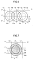
- Fig. 4 is a diagram showing a change in the toner particle caused by the fixing device according to this embodiment.
- q [(p1) 2 + (p2) 2 ] 1/2
- q (2 ⁇ p 2 ) 1/2 ⁇ 1.4p
- the individual toner particles 15 constituting the toner image are melted and become flat after pressed against the paper 17, so that their diameters become about twice as large as the diameter of the toner particle 15 before the fixing process. Since the diameter d2 of the toner particle 15 is set to 0.7p - 1.0p in this embodiment as described above, the diameter of the fixed toner particle becomes 1.4p - 2.0p.
- the diameter of the fixed toner particle become about 1.2 - 2.0 times as large as the diameter d2 of the toner particle and depends on conditions such as temperature and pressure at the fixing process.
- a lowest limit of the diameter of the toner particle before the fixing process is equal to or more than a value which is determined in such a way that the toner particles neighboring in a diagonal direction are in contact with each other.
- highest limit of the toner particle before the fixing process is 1.0p.
- the toner particle 15a having the diameter d2 of 0.7p is used, as shown in Fig. 3, the diameter of the fixed toner particle 25a becomes 1.4p, as shown in Fig. 4. Accordingly, the toner particles are connected not only on the lines L1 and L2 but also on the diagonal lines L3, as shown in Fig. 4. As a result, the fixed toner image can be prevented from being discontinuous, so that the image quality can be improved.
- Fig. 5 is a diagram showing the toner particles 15a and 15b transferred on the paper 17 and the toner particles 25a and 25b fixed on the paper 17, when the diameter d2 of the toner particles 15a and 15b is larger than 1.0p.
- the fixed toner particles 25a and 25b extends over the neighboring lines, for example, the line L2a, on which no image should be formed or a white line is formed, thereby degrading the image quality.
- Fig. 6 is a diagram showing irradiated spots 31a, 31b and 31c and toner particles 15a, 15b and 15c on the surface of the photosensitive drum 11.
- the toner particles 15a, 15b and 15c overlap each other, they are easy to shift from the intersections of the lines L1 and L2.
- the large amount of toner particles are transferred and fixed on the positions shifted from the intersections of the lines L1 and L2, thereby degrading the image quality.
- Fig. 7 is a diagram showing a change in the toner particle caused by the fixing device when the toner particles having the diameter being larger than the pitch of the grid is used.
- a plurality of lines set on the photosensitive drum 11 (in Fig. 2) and extending in the main-scanning direction are denoted by L1
- a plurality of lines set on the photosensitive drum 11 and extending in the paper-feed direction (sub-scanning direction) are denoted by L2.
- the lines L1 and L2 constitute the grid. Further, the lines L1 and L2 are arranged, being spaced apart by the pitch p which is determined by the resolution of the electrophotographic printer.
- a reference numeral 31c denotes an irradiated spot
- a reference numeral 15c denotes toner attached to the irradiated spot 31c
- a reference numeral 25c denotes toner after the fixing process.
- the diameter d2 of the toner particle 15c is set to be larger than the diameter d1 of the irradiated spot 31c.
- the toner particle 15c having the diameter d2 being larger than the diameter d1 of the irradiated spot 31c is used, the toner particle 15c can not be attached to the irradiated spot 31c precisely by the developing device 14.
- the toner particle 25c after the fixing will be positioned, being greatly deviated from the location corresponding to the irradiated spot 31c, thus degrading the image quality.
- the diameter d2 of the toner particle 15 is set to be smaller than 1.0p, as described before.
- the toner particles 15 are prepared by polymerization, variations in the diameters d2 of 90% of the toner particles 15 can be made to fall within the range of approximately 5 [ ⁇ m]. Thus, by means of polymerization, at least 90 % of the whole toner particles contained in the fixing device can be easily made to have the diameter d2 of 0.7p - 1.0p.
- the pitch set on the photosensitive drum 11 becomes approximately 21 [ ⁇ m]
- the diameter d2 of the toner particle 15 is set to approximately 15 [ ⁇ m] - 21 [ ⁇ m].
- the diameter of the toner particle can be made to be larger than that of the toner particle conventionally used.
- the diameter d2 of the toner particle 15 is large, not only the transfer efficiency can be increased, but also the cleaning capability of the cleaning device 18 can be improved.
- the toner particles 15 is inhibited from floating in the air, and the environment can be thereby prevented from being polluted.
Abstract
Description
Claims (9)
- An electrophotographic image forming apparatus comprising:an image carrier (11);a charging device (12) for charging a surface of said image carrier (11);a light beam scanner (13) for projecting a light beam on the surface of said image carrier (11), thereby forming irradiated spots (31a, 31b, 31c) constituting an electrostatic latent image on the surface of said image carrier (11), said irradiated spots (31a, 31b, 31c) being formed on intersections of a grid which is composed of a plurality of first lines (L1) extending on the surface of said image carrier (11) in a main-scanning direction and arranged at equal first intervals and a plurality of second lines (L2) extending on the surface of said image carrier (11) in a sub-scanning direction perpendicular to the main-scanning direction and arranged at equal second intervals;a developing device (22) for attaching a toner particle (15) to each of the irradiated spots (31a, 31b, 31c) on the surface of said image carrier (11) to form a toner image on the surface of said image carrier (11);a transfer device (16) for transferring the toner particle (15) to a transfer material (17); anda fixing device (30) for fixing the toner particle (15) on the transfer material (17);
wherein said developing device (14) contains the toner particles (15), each diameter of which is determined in such a way that each diameter of fixed toner particles (25a) is equal to approximately a length (q) of a diagonal line (L3) of the grid. - An electrophotographic image forming apparatus of Claim 1, wherein the each diameter of the toner particles (15) in said developing device (14) is in a range of 0.7 times to 1.0 times as long as the first interval.
- An electrophotographic image forming apparatus of Claim 2, wherein the each diameter of the toner particles (15) in said developing device (14) is in a range of 0.7 times to 1.0 times as long as the second interval.
- An electrophotographic image forming apparatus of Claim 1, wherein the each diameter of the toner particles (15) in said developing device (14) is in a range of 0.7 times to 1.0 times as long as the second interval.
- An electrophotographic image forming apparatus of Claim 1, wherein a relative ratio of the toner particles (15) having diameters, which are determined in such a way that each diameter of fixed toner particles (25a) is equal to approximately the length (q) of the diagonal line (L3) of the grid, to whole toner particles in said developing device (14) is not less than 90 %.
- A method for electrophotographically forming an image comprising the steps of:charging a surface of a image carrier (11);projecting a light beam on the surface of said image carrier (11), thereby forming irradiated spots (31a, 31b, 31c) constituting an electrostatic latent image on the surface of said image carrier (11), said irradiated spot (31a, 31b, 31c) being formed on intersections of a grid which is composed of a plurality of first lines (L1) extending on the surface of said image carrier in a main-scanning direction and arranged at equal first intervals and a plurality of second lines (L2) extending on the surface of said image carrier in a sub-scanning direction perpendicular to the main-scanning direction and arranged at equal second intervals;attaching a toner particle (15) to the irradiated spot on the surface of said image carrier (11);transferring the toner particle (15) to a transfer material (17); andfixing the toner particle (15) on the transfer material (17);
wherein a diameter of the toner particle (15) is determined in such a way that a diameter of a fixed toner particle (25a) is equal to approximately a length (q) of a diagonal line (L3) of the grid. - A method of Claim 6, wherein the diameter of the toner particle (15) before the fixing step is in a range of 0.7 times to 1.0 times as long as the first interval.
- A method of Claim 7, wherein the diameter of the toner particle (15) before the fixing step is in a range of 0.7 times to 1.0 times as long as the second interval.
- A method of Claim 6, wherein the diameter of the toner particle (15) before the fixing step is in a range of 0.7 times to 1.0 times as long as the second interval.
Applications Claiming Priority (3)
| Application Number | Priority Date | Filing Date | Title |
|---|---|---|---|
| JP302887/96 | 1996-11-14 | ||
| JP30288796 | 1996-11-14 | ||
| JP30288796A JPH10138549A (en) | 1996-11-14 | 1996-11-14 | Electrophotographic printer |
Publications (2)
| Publication Number | Publication Date |
|---|---|
| EP0843227A1 true EP0843227A1 (en) | 1998-05-20 |
| EP0843227B1 EP0843227B1 (en) | 2003-02-26 |
Family
ID=17914306
Family Applications (1)
| Application Number | Title | Priority Date | Filing Date |
|---|---|---|---|
| EP97119175A Expired - Lifetime EP0843227B1 (en) | 1996-11-14 | 1997-11-03 | Electrophotographic image forming apparatus |
Country Status (4)
| Country | Link |
|---|---|
| US (1) | US5930568A (en) |
| EP (1) | EP0843227B1 (en) |
| JP (1) | JPH10138549A (en) |
| DE (1) | DE69719290T2 (en) |
Families Citing this family (2)
| Publication number | Priority date | Publication date | Assignee | Title |
|---|---|---|---|---|
| JPH11115238A (en) * | 1997-10-09 | 1999-04-27 | Ricoh Co Ltd | Image forming apparatus |
| JP2004219654A (en) | 2003-01-14 | 2004-08-05 | Oki Data Corp | Image forming apparatus |
Citations (2)
| Publication number | Priority date | Publication date | Assignee | Title |
|---|---|---|---|---|
| EP0330498A2 (en) * | 1988-02-24 | 1989-08-30 | Canon Kabushiki Kaisha | Non-magnetic toner |
| EP0712048A1 (en) * | 1994-11-08 | 1996-05-15 | Canon Kabushiki Kaisha | Image forming method and image forming apparatus |
Family Cites Families (5)
| Publication number | Priority date | Publication date | Assignee | Title |
|---|---|---|---|---|
| US4060323A (en) * | 1974-07-10 | 1977-11-29 | Canon Kabushiki Kaisha | Image information handling method and device |
| JPS5726962A (en) * | 1980-07-25 | 1982-02-13 | Matsushita Electric Ind Co Ltd | Photoradiation method for recorder |
| JPH04369664A (en) * | 1991-06-19 | 1992-12-22 | Canon Inc | Image forming method |
| JPH07295320A (en) * | 1994-04-26 | 1995-11-10 | Canon Inc | Image forming device |
| JP3577674B2 (en) * | 1994-08-12 | 2004-10-13 | 章雄 飯田 | Dust removal device for dust removal equipment |
-
1996
- 1996-11-14 JP JP30288796A patent/JPH10138549A/en active Pending
-
1997
- 1997-11-03 DE DE69719290T patent/DE69719290T2/en not_active Expired - Lifetime
- 1997-11-03 EP EP97119175A patent/EP0843227B1/en not_active Expired - Lifetime
- 1997-11-06 US US08/965,409 patent/US5930568A/en not_active Expired - Lifetime
Patent Citations (2)
| Publication number | Priority date | Publication date | Assignee | Title |
|---|---|---|---|---|
| EP0330498A2 (en) * | 1988-02-24 | 1989-08-30 | Canon Kabushiki Kaisha | Non-magnetic toner |
| EP0712048A1 (en) * | 1994-11-08 | 1996-05-15 | Canon Kabushiki Kaisha | Image forming method and image forming apparatus |
Also Published As
| Publication number | Publication date |
|---|---|
| DE69719290T2 (en) | 2003-08-21 |
| DE69719290D1 (en) | 2003-04-03 |
| US5930568A (en) | 1999-07-27 |
| EP0843227B1 (en) | 2003-02-26 |
| JPH10138549A (en) | 1998-05-26 |
Similar Documents
| Publication | Publication Date | Title |
|---|---|---|
| EP0932085A1 (en) | Image forming device and image forming method | |
| GB2138162A (en) | Scanning optical system | |
| EP0354310A1 (en) | Method and apparatus for electrophotographic printing | |
| JP3762198B2 (en) | Image forming apparatus | |
| US5930568A (en) | Electrophotographic image forming apparatus | |
| US5689777A (en) | Image forming apparatus having contact charger | |
| US6342910B1 (en) | Image forming apparatus to form smooth image with inconspicuous granularity | |
| JP2000047462A (en) | Electrophotographic device and exposing device | |
| EP1059804A2 (en) | Apparatus and method for forming image with high image reproducibility | |
| US6448989B1 (en) | Image forming apparatus using digital light as image exposure means | |
| JPH10240004A (en) | Image forming device | |
| JP2004219654A (en) | Image forming apparatus | |
| JPH11196277A (en) | Image forming device | |
| JP3882877B2 (en) | Image forming method | |
| KR100346682B1 (en) | Printing unit for wet type electrophotographic printer | |
| JP2943229B2 (en) | Image forming device | |
| JP3920553B2 (en) | Latent image carrier and image forming apparatus | |
| JPH1178123A (en) | Method and system for forming digital image | |
| JPH09258534A (en) | Electrophotographic recorder | |
| JP2912258B2 (en) | Back exposure recording image forming device | |
| US7071960B2 (en) | Image forming apparatus | |
| JPH11125938A (en) | Image forming device | |
| JP2007098681A (en) | Electrophotographic image forming apparatus | |
| JP2002014525A (en) | Image forming method and image forming device | |
| JPH05273833A (en) | Image forming device |
Legal Events
| Date | Code | Title | Description |
|---|---|---|---|
| PUAI | Public reference made under article 153(3) epc to a published international application that has entered the european phase |
Free format text: ORIGINAL CODE: 0009012 |
|
| AK | Designated contracting states |
Kind code of ref document: A1 Designated state(s): DE FR GB |
|
| AX | Request for extension of the european patent |
Free format text: AL;LT;LV;RO;SI |
|
| 17P | Request for examination filed |
Effective date: 19980917 |
|
| AKX | Designation fees paid |
Free format text: DE FR GB |
|
| RBV | Designated contracting states (corrected) |
Designated state(s): DE FR GB |
|
| 17Q | First examination report despatched |
Effective date: 20000531 |
|
| GRAG | Despatch of communication of intention to grant |
Free format text: ORIGINAL CODE: EPIDOS AGRA |
|
| GRAG | Despatch of communication of intention to grant |
Free format text: ORIGINAL CODE: EPIDOS AGRA |
|
| GRAH | Despatch of communication of intention to grant a patent |
Free format text: ORIGINAL CODE: EPIDOS IGRA |
|
| GRAH | Despatch of communication of intention to grant a patent |
Free format text: ORIGINAL CODE: EPIDOS IGRA |
|
| GRAA | (expected) grant |
Free format text: ORIGINAL CODE: 0009210 |
|
| AK | Designated contracting states |
Designated state(s): DE FR GB |
|
| REG | Reference to a national code |
Ref country code: GB Ref legal event code: FG4D |
|
| REF | Corresponds to: |
Ref document number: 69719290 Country of ref document: DE Date of ref document: 20030403 Kind code of ref document: P |
|
| ET | Fr: translation filed | ||
| PLBE | No opposition filed within time limit |
Free format text: ORIGINAL CODE: 0009261 |
|
| STAA | Information on the status of an ep patent application or granted ep patent |
Free format text: STATUS: NO OPPOSITION FILED WITHIN TIME LIMIT |
|
| 26N | No opposition filed |
Effective date: 20031127 |
|
| PGFP | Annual fee paid to national office [announced via postgrant information from national office to epo] |
Ref country code: FR Payment date: 20131108 Year of fee payment: 17 Ref country code: GB Payment date: 20131030 Year of fee payment: 17 Ref country code: DE Payment date: 20131030 Year of fee payment: 17 |
|
| REG | Reference to a national code |
Ref country code: DE Ref legal event code: R119 Ref document number: 69719290 Country of ref document: DE |
|
| GBPC | Gb: european patent ceased through non-payment of renewal fee |
Effective date: 20141103 |
|
| REG | Reference to a national code |
Ref country code: FR Ref legal event code: ST Effective date: 20150731 |
|
| PG25 | Lapsed in a contracting state [announced via postgrant information from national office to epo] |
Ref country code: DE Free format text: LAPSE BECAUSE OF NON-PAYMENT OF DUE FEES Effective date: 20150602 Ref country code: GB Free format text: LAPSE BECAUSE OF NON-PAYMENT OF DUE FEES Effective date: 20141103 |
|
| PG25 | Lapsed in a contracting state [announced via postgrant information from national office to epo] |
Ref country code: FR Free format text: LAPSE BECAUSE OF NON-PAYMENT OF DUE FEES Effective date: 20141201 |