EP0842859A2 - Plastic bottle and method for manufacturing and packaging thereof - Google Patents
Plastic bottle and method for manufacturing and packaging thereof Download PDFInfo
- Publication number
- EP0842859A2 EP0842859A2 EP97118222A EP97118222A EP0842859A2 EP 0842859 A2 EP0842859 A2 EP 0842859A2 EP 97118222 A EP97118222 A EP 97118222A EP 97118222 A EP97118222 A EP 97118222A EP 0842859 A2 EP0842859 A2 EP 0842859A2
- Authority
- EP
- European Patent Office
- Prior art keywords
- bottle
- cap
- bottle according
- bottles
- thermoplastic material
- Prior art date
- Legal status (The legal status is an assumption and is not a legal conclusion. Google has not performed a legal analysis and makes no representation as to the accuracy of the status listed.)
- Granted
Links
Images


Classifications
-
- B—PERFORMING OPERATIONS; TRANSPORTING
- B29—WORKING OF PLASTICS; WORKING OF SUBSTANCES IN A PLASTIC STATE IN GENERAL
- B29C—SHAPING OR JOINING OF PLASTICS; SHAPING OF MATERIAL IN A PLASTIC STATE, NOT OTHERWISE PROVIDED FOR; AFTER-TREATMENT OF THE SHAPED PRODUCTS, e.g. REPAIRING
- B29C49/00—Blow-moulding, i.e. blowing a preform or parison to a desired shape within a mould; Apparatus therefor
- B29C49/42—Component parts, details or accessories; Auxiliary operations
- B29C49/48—Moulds
- B29C49/52—Moulds having decorating or printing means
-
- B—PERFORMING OPERATIONS; TRANSPORTING
- B65—CONVEYING; PACKING; STORING; HANDLING THIN OR FILAMENTARY MATERIAL
- B65D—CONTAINERS FOR STORAGE OR TRANSPORT OF ARTICLES OR MATERIALS, e.g. BAGS, BARRELS, BOTTLES, BOXES, CANS, CARTONS, CRATES, DRUMS, JARS, TANKS, HOPPERS, FORWARDING CONTAINERS; ACCESSORIES, CLOSURES, OR FITTINGS THEREFOR; PACKAGING ELEMENTS; PACKAGES
- B65D1/00—Containers having bodies formed in one piece, e.g. by casting metallic material, by moulding plastics, by blowing vitreous material, by throwing ceramic material, by moulding pulped fibrous material, by deep-drawing operations performed on sheet material
- B65D1/02—Bottles or similar containers with necks or like restricted apertures, designed for pouring contents
- B65D1/0223—Bottles or similar containers with necks or like restricted apertures, designed for pouring contents characterised by shape
-
- B—PERFORMING OPERATIONS; TRANSPORTING
- B65—CONVEYING; PACKING; STORING; HANDLING THIN OR FILAMENTARY MATERIAL
- B65D—CONTAINERS FOR STORAGE OR TRANSPORT OF ARTICLES OR MATERIALS, e.g. BAGS, BARRELS, BOTTLES, BOXES, CANS, CARTONS, CRATES, DRUMS, JARS, TANKS, HOPPERS, FORWARDING CONTAINERS; ACCESSORIES, CLOSURES, OR FITTINGS THEREFOR; PACKAGING ELEMENTS; PACKAGES
- B65D21/00—Nestable, stackable or joinable containers; Containers of variable capacity
- B65D21/02—Containers specially shaped, or provided with fittings or attachments, to facilitate nesting, stacking, or joining together
- B65D21/0209—Containers specially shaped, or provided with fittings or attachments, to facilitate nesting, stacking, or joining together stackable or joined together one-upon-the-other in the upright or upside-down position
- B65D21/023—Closed containers provided with local cooperating elements in the top and bottom surfaces, e.g. projection and recess
- B65D21/0231—Bottles, canisters or jars whereby the neck or handle project into a cooperating cavity in the bottom
-
- B—PERFORMING OPERATIONS; TRANSPORTING
- B65—CONVEYING; PACKING; STORING; HANDLING THIN OR FILAMENTARY MATERIAL
- B65D—CONTAINERS FOR STORAGE OR TRANSPORT OF ARTICLES OR MATERIALS, e.g. BAGS, BARRELS, BOTTLES, BOXES, CANS, CARTONS, CRATES, DRUMS, JARS, TANKS, HOPPERS, FORWARDING CONTAINERS; ACCESSORIES, CLOSURES, OR FITTINGS THEREFOR; PACKAGING ELEMENTS; PACKAGES
- B65D23/00—Details of bottles or jars not otherwise provided for
-
- B—PERFORMING OPERATIONS; TRANSPORTING
- B65—CONVEYING; PACKING; STORING; HANDLING THIN OR FILAMENTARY MATERIAL
- B65D—CONTAINERS FOR STORAGE OR TRANSPORT OF ARTICLES OR MATERIALS, e.g. BAGS, BARRELS, BOTTLES, BOXES, CANS, CARTONS, CRATES, DRUMS, JARS, TANKS, HOPPERS, FORWARDING CONTAINERS; ACCESSORIES, CLOSURES, OR FITTINGS THEREFOR; PACKAGING ELEMENTS; PACKAGES
- B65D41/00—Caps, e.g. crown caps or crown seals, i.e. members having parts arranged for engagement with the external periphery of a neck or wall defining a pouring opening or discharge aperture; Protective cap-like covers for closure members, e.g. decorative covers of metal foil or paper
- B65D41/32—Caps or cap-like covers with lines of weakness, tearing-strips, tags, or like opening or removal devices, e.g. to facilitate formation of pouring openings
- B65D41/34—Threaded or like caps or cap-like covers provided with tamper elements formed in, or attached to, the closure skirt
- B65D41/3495—Threaded or like caps or cap-like covers provided with tamper elements formed in, or attached to, the closure skirt the tamper element being bonded or adhered to the container wall
-
- B—PERFORMING OPERATIONS; TRANSPORTING
- B29—WORKING OF PLASTICS; WORKING OF SUBSTANCES IN A PLASTIC STATE IN GENERAL
- B29C—SHAPING OR JOINING OF PLASTICS; SHAPING OF MATERIAL IN A PLASTIC STATE, NOT OTHERWISE PROVIDED FOR; AFTER-TREATMENT OF THE SHAPED PRODUCTS, e.g. REPAIRING
- B29C2949/00—Indexing scheme relating to blow-moulding
- B29C2949/07—Preforms or parisons characterised by their configuration
- B29C2949/0715—Preforms or parisons characterised by their configuration the preform having one end closed
-
- B—PERFORMING OPERATIONS; TRANSPORTING
- B29—WORKING OF PLASTICS; WORKING OF SUBSTANCES IN A PLASTIC STATE IN GENERAL
- B29C—SHAPING OR JOINING OF PLASTICS; SHAPING OF MATERIAL IN A PLASTIC STATE, NOT OTHERWISE PROVIDED FOR; AFTER-TREATMENT OF THE SHAPED PRODUCTS, e.g. REPAIRING
- B29C49/00—Blow-moulding, i.e. blowing a preform or parison to a desired shape within a mould; Apparatus therefor
- B29C49/02—Combined blow-moulding and manufacture of the preform or the parison
- B29C49/06—Injection blow-moulding
-
- B—PERFORMING OPERATIONS; TRANSPORTING
- B29—WORKING OF PLASTICS; WORKING OF SUBSTANCES IN A PLASTIC STATE IN GENERAL
- B29L—INDEXING SCHEME ASSOCIATED WITH SUBCLASS B29C, RELATING TO PARTICULAR ARTICLES
- B29L2031/00—Other particular articles
- B29L2031/712—Containers; Packaging elements or accessories, Packages
- B29L2031/7158—Bottles
-
- B—PERFORMING OPERATIONS; TRANSPORTING
- B65—CONVEYING; PACKING; STORING; HANDLING THIN OR FILAMENTARY MATERIAL
- B65D—CONTAINERS FOR STORAGE OR TRANSPORT OF ARTICLES OR MATERIALS, e.g. BAGS, BARRELS, BOTTLES, BOXES, CANS, CARTONS, CRATES, DRUMS, JARS, TANKS, HOPPERS, FORWARDING CONTAINERS; ACCESSORIES, CLOSURES, OR FITTINGS THEREFOR; PACKAGING ELEMENTS; PACKAGES
- B65D2203/00—Decoration means, markings, information elements, contents indicators
-
- B—PERFORMING OPERATIONS; TRANSPORTING
- B65—CONVEYING; PACKING; STORING; HANDLING THIN OR FILAMENTARY MATERIAL
- B65D—CONTAINERS FOR STORAGE OR TRANSPORT OF ARTICLES OR MATERIALS, e.g. BAGS, BARRELS, BOTTLES, BOXES, CANS, CARTONS, CRATES, DRUMS, JARS, TANKS, HOPPERS, FORWARDING CONTAINERS; ACCESSORIES, CLOSURES, OR FITTINGS THEREFOR; PACKAGING ELEMENTS; PACKAGES
- B65D2501/00—Containers having bodies formed in one piece
- B65D2501/0009—Bottles or similar containers with necks or like restricted apertures designed for pouring contents
- B65D2501/0054—Lines of weakness
Definitions
- the present invention relates to a plastic bottle, in particular for mineral water or for drinks, and to a method for manufacturing and packaging thereof.
- Another problem relating to packaging of the bottles is that of closing the bottles with caps provided with a so-called "seal of guarantee".
- the need to attach this seal generally makes it impossible to make the cap from the same material as the bottle, since the seal is normally made with a collar formed as one piece with the cap, which is generally produced from a material different from that used to form the bottle.
- the problems which are thus caused for those who perform recycling of the bottles are not of an insignificant nature.
- the object of the present invention is to provide a bottle in which all the data intended for the consumer is provided without using paper labels, printing, serigraphy, paints and the like.
- a further object of the invention is to provide a system for closing bottles which allows the use of only one material for the cap, seal and bottle and which therefore makes this assembly totally recyclable.
- the present invention also relates to a method for manufacturing and packaging plastic bottles, whereby the bottle produced is provided directly on its surface with the data which is generally supplied on the label and whereby the bottles may be made so as to provide a packaging of the so-called "monomatier" type.
- the present invention therefore relates to a plastic bottle, in particular for mineral water or similar drinks, which can be closed by means of a cap, for example of the screw type, provided with sealing means, characterized in that said bottle has all the marketing and/or legally required information, necessary for identification of the product intended for it, formed directly, by means of deformation or similar structural modification, on the wall of said bottle.
- said means for sealing the said cap comprise one or more elements connecting said cap and said bottle, arranged uniformly along the external edge of said cap and made of thermoplastic material.
- the cap, connecting elements and bottle are made of the same thermoplastic material.
- the bottle according to the invention must be designed so as to facilitate both storage thereof during the pre-packaging stage and collection thereof after use.
- the invention further relates to a method for manufacturing and packaging bottles, preferably made of plastic, in particular for mineral water or similar drinks, in which the stage of manufacture of said bottles comprises the steps of:
- the present invention also relates to a method for manufacturing and packaging bottles, preferably made of plastic, in particular for mineral water or similar drinks, in which the stage of packaging of said bottles comprises the steps of:
- FIG. 1 denotes a bottle according to the present invention.
- Said bottle containing a liquid 10, in particular water, has on its surface the label areas 101 with, directly formed on them, the graphic and/or text elements necessary for commercial identification and display of the legally required data, such as expiry date, composition and other analytical statistics relating to the product 10 contained in the bottle 1.
- the bottle is moreover closed by means of a cap and said cap has sealing means 3.
- Figure 2 shows a longitudinally sectioned view of a portion of a mould of the type used in the method for manufacturing bottles according to the invention with, facing it, a portion of the wall of the bottle 1.
- the mould 4 has cooling channels 104, of the type known per se.
- a varied-cooling system i.e. a block 204 in which there are formed channels 504, the circuit of which is separate from that of the channels 104 of the mould.
- the background zones 121 of the label area 101 on the surface of the bottle 1 are cooled by means of the circuit 504 formed in the block 204, whereas the graphic elements or characters 111, which are contained in the block 304, isolated from the block 204 by means of the layer 314 of insulating material, are cooled homogeneously with the remainder of the bottle 1.
- the channels 324 of the block 304 are connected, on the other hand, to the primary cooling circuit, i.e. to the channels 104.
- Cooling of the mould may be performed in a known manner, using water or other cooling fluids within an average temperature range (10-60°C) as regards the so-called primary circuit consisting of the channels 104; cooling in the secondary circuit of the channels 504 of the block 204 will be performed at significantly lower temperatures, for example using liquid nitrogen or liquid air.
- the procedure may be reversed, namely more opaque writing may be formed on a shinier background.
- heating or rapid super-heating may be performed by means of the channels 504, useful for obtaining the aforementioned differentiation.
- the differentiation between the background of the label formed directly on the surface of the bottle and the graphic elements and/or characters contained thereon may also be obtained by means of operations of a mechanical type, for example by performing glossing or sand-blasting of the background compared to the characters or vice-versa.
- electrical or electronic treatment may be envisaged, which is also able to achieve the same result, as well as laser or ultrasound treatment.
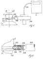
- Figure 4 shows in schematic form the final stage of manufacture of a bottle according to the method of the invention.
- the bottle 1 has been filled and has been closed by placing the cap 2 on its mouth.
- the distributor unit 6 deposits, by means of the nozzle 206 connected thereto via the pipe 106, the droplets 103 of a jet of viscous fluid material, preferably of the hot melt type, i.e. a jet of thermoplastic polymer.
- the droplets 103 form the means for sealing the closure of the bottle, being arranged between the external edge of the cap 2 and the annular swelling 211 which surrounds the neck 201 of the bottle 1.
- the uniform deposition of the droplets 103 of hot melt material is made possible by the fact that the bottle is rotated with respect to its vertical axis in the direction indicated by the arrow IV.
- Figure 5 shows a variation of embodiment of the final stage of packaging of a bottle according to the method of the invention.
- the bottle 1 is also in this case filled and closed with the cap 2; however, the distributor unit 106 delivers, by means of the delivery head 306 provided with the nozzle 406, a continuous bead 203 of material of the type described above, which is deposited over the entire circumference of the neck 201 of the bottle, in the interstice comprised between the external edge of the cap 2 and the annular swelling 211.
- the uniform deposition of the continuous bead 203 is permitted by the fact that the bottle 1 is made to rotate about its longitudinal axis in the direction indicated by the arrow V, via suitable means not illustrated in the figure.
- FIG. 6 illustrates a detail of the variation of embodiment according to Figure 6.
- the nozzle 406 is provided in this case with a delivery valve 506 which comprises a needle obturator 516 co-operating with the seat 536 and biased by a spring 526.
- a delivery valve 506 which comprises a needle obturator 516 co-operating with the seat 536 and biased by a spring 526.
- the needle of the obturator 516 pushes the latter into the seat 526 and causes the emergence of the viscous fluid material forming the bead 203.
- the delivery valve 506 is enclosed by the obturator 516 pushed by the spring 526, and delivery stops.
- the material delivered by the distributor unit 6 is preferably the same material from which the bottle is made; it is also preferable that the cap of the bottle should also be made of the same material as the bottle.
- the connecting elements which form the means 3 for sealing the cap and the bottle may be made by thermo-welding directly spotwise the external edge of the cap itself onto the neck of the bottle, using suitable means such as, for example, laser and/or ultrasound.
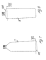
- Figures 7 and 8 illustrate two variations of embodiment of the bottle according to the present invention.
- Both the bottle 7 of Figure 7 and the bottle 8 of Figure 8 are formed with a tapered tubular body; in the case of the bottle 7, tapering is from the bottom upwards, being exactly the opposite in the case of the bottle 8.
- tapering is from the bottom upwards, being exactly the opposite in the case of the bottle 8.
- the bottles of the type illustrated in Figures 7 and 8, respectively may be introduced inside one another, allowing a considerable saving in space in the containers which are to be collected for the purposes of recycling.
- Figure 9 shows two bottles 9, 9', similar to that illustrated in Figure 7, except that they have the helical groove 209, 209' on the side wall.
- the portions 109, 109' of the two bottles are separated from the remainder of the bottle except for the strips 119, 119'.
- the Figure clearly illustrates the function of the helical groove 209, 209' which favours mutual engagement between the external surface of the bottle 9' and the internal surface of the bottle 9. In this way the two bottles remain firmly engaged in the configuration shown in the figure and this allows optimisation in the management of the spaces for collection of the material to be recycled.
- Figure 10 shows a detail of a bottle of the type illustrated in Figure 7, together with means for partial separation of the portion 107.
- the bottle 7 is inserted with its bottom into a cylindrical base 10 provided with an axial cavity 11 having a diameter matching the diameter of the bottom of the bottle 7.
- the portion 107 of the bottle is delimited by a groove 127; at a given point along the groove a radial recess 137 is formed.
- This recess favours the insertion of the blade 12 housed in the base 10 and mounted on a button 14 loaded by the spring 13.
- the recess 137 is formed alongside a strip 117 which is devoid of the groove 127.
- Figures 12 to 14 illustrate a variation of embodiment of the bottle illustrated in Figures 7 to 9 and described above.
- Figure 12 shows a bottle 20 of substantially cylindrical symmetry, provided with a transverse groove 21 formed in the region of the bottom portion 25, similar to the groove 127 of the bottle 7 illustrated in Figure 7.
- the said bottle 20 is provided, moreover, with a longitudinal groove 22; at the intersection of this longitudinal groove with the transverse groove 21 a recess 23 is formed.
- Figure 13 illustrates a cross-sectional detail of the bottle 20, together with the cutting means 30.
- the cutting means comprise an annular element 30 provided with an open cylindrical cavity 31 inside which the bottle 20 is positioned.
- the blade 32 associated with the button 32 is directed towards the recess 24, in a manner entirely similar to that described previously with reference to Figure 10.
- An additional blade 36 is positioned in the element 30 in a diametrically opposite position, being arranged on a plane at right angles to that of the blade 32. This blade is directed towards the recess 23 located at the intersection of the groove 21 with the groove 22.
- the side wall of the bottle 20 can be cut along the groove 22. In this way, as illustrated in Figure 14, several cylindrical bottles may be stacked on top of one another without force.
- Figures 16A and 16B show more clearly the variation in the cross-section of the folds 42.
- the cross-section taken along the line A-A of Figure 15 and illustrated in Figure 16A is significantly smaller than that taken along the line B-B and illustrated in Figure 16B.
- the bottles 40 after partial removal of the portion 43, the bottles 40, as illustrated in Figure 17, may be easily stacked on top of one another, thanks to the possibility of expansion conferred on the bottle 40 by the folds 42.
- the folds 42 may be similarly formed with a constant cross-section or also formed with an extension other than the longitudinal extension, such as for example a helical extension.
- the bottle moreover may be designed for separation of an end portion, as illustrated in the figures, or also designed for separation into two substantially identical halves, the folds being advantageously formed with a cross-section increasing towards the centre of the bottle body and decreasing towards the ends.
- the folds, shown directed towards the inside of the bottle in the figures described above may also be formed directed towards the outside, in particular in bottles intended for gassy drinks.
- Figure 18 illustrates a further variation of embodiment of the bottle according to the present invention.
- the bottom 51 of the bottle 50 is provided axially with a cavity 52 provided on its external edge with the annular relief 53 having a toothed profile. This cavity allows the insertion of the mouth of another bottle inside it, so as to be able to organise the bottles in long rows between the manufacturing stage and the subsequent packaging stage.
- FIGs 21 and 22 is shown another embodiment of the present invention.
- a bottle 70 is provided, on its bottom 71, with several diametral grooves 72 formed on the surface of the said bottom 71. At the intersection of such grooves 72, there is provided a cavity directed to the inside of the bottle 70.
- FIG 23 is shown a bottle 70' that penetrate into the bottle 70 throgh the bottom 71, crushing the said bottom 71 with its neck 74' provided with the cap 75'.
- the wall of the bottom 71 of the bottle 70 is weakened by the grooves 72 and by the cavity 73, so as to facilitate such a penetration.
- a bottle for example provided with folds on its lateral surface or a bottle formed tapered from his mouth to its bottom, as described above, can advantageously provided with the groveed bottom as shown in Figures 21 to 23.
- the stacking of such a bottle can achieve excellent results.
Abstract
Description
- introducing material into a mould;
- blowing and forming the bottle from said material;
- simultaneously forming, directly on the surface of the bottle, in the form of a label comprising a background and one or more graphic and/or text elements, all the marketing and/or legally required information necessary for identification of the product intended for said bottle; and
- differentiation between the background and the graphic and/or text elements of said label formed on the surface of said bottle.
- filling the bottles;
- closing the bottles by means of a cap, for example of the screw type;
- affixing sealing means to said cap, said sealing means comprising one or more elements connecting said cap and said bottle, arranged uniformly along the external edge of said cap using suitable connection means.
Claims (35)
- Plastic bottle, in particular for mineral water or similar drinks, which can be closed by means of a cap (2), for example of the screw type, provided with sealing means (3), characterized in that said bottle (1) has all the marketing and/or legally required information (101) necessary for identification of the product intended for it, formed directly, by means of deformation or similar modification, on the wall of said bottle (1).
- Bottle according to Claim 1, characterized in that said means (3) for sealing the said cap (2) comprise one or more elements (103, 203) connecting said cap (2) and said bottle (1), arranged uniformly along the external edge of said cap (2) and made of thermoplastic material.
- Bottle according to Claim 2, in which said connecting elements comprise a plurality of droplets (103) of thermoplastic material.
- Bottle according to Claim 2, in which said connecting elements comprise a continuous bead (203) of thermoplastic material.
- Bottle according to any one of the preceding claims 2 to 4, in which said thermoplastic material is the same material from which said bottle is made.
- Bottle according to any one of Claims 1 to 5, characterized in that said cap (2) is made of thermoplastic material.
- Bottle according to Claim 6, in which said thermoplastic material is the same material from which said bottle is made.
- Bottle according to Claim 6 or 7, in which said connecting elements are obtained directly from the cap (2) itself, by means of thermo-welding or electro-welding.
- Bottle according to any one of the preceding claims 1 to 8, in which, in the vicinity of one of the two ends of the bottle, there are formed receiving means (127, 137; 21; 24; 41) for cutting means (12; 32) so as to perform the separation between the portion of the said end (107, 108, 109, 25, 43) of the bottle (7, 8, 9, 20, 40) and the bottle itself, except for a strip (117, 119) which joins said portion (107, 108, 109) to said bottle (7, 8, 9).
- Bottle according to Claim 9, in which said receiving means comprise a groove (127, 21, 41) formed transversely on the wall of said bottle and a radial recess (137, 24) arranged inside said groove.
- Bottle according to Claim 10, in which the side wall of the said bottle (20) has formed on it receiving means (22, 23) for cutting means (36) so as to cut longitudinally into this side wall.
- Bottle according to Claim 11, in which said receiving means comprise a transverse groove (22) substantially perpendicular to the transverse groove (21), a recess (23) being formed at the intersection between said grooves (21, 22).
- Bottle according to Claim 9 or 10, in which said bottle (40) has one or more open folds (42) along the side walls.
- Bottle according to Claim 13, in which said folds (42) have a cross-section increasing towards the removable end (43).
- Bottle according to Claim 9 and Claim 13, in which said receiving means are arranged along the transverse axis of said bottle, said folds being formed with a cross-section increasing towards the centre and decreasing towards the ends thereof.
- Bottle according to Claim 9 or 10, characterized in that said bottle (7, 9) is formed tapered from the bottom towards the mouth.
- Bottle according to Claim 9 or 10, characterized in that said bottle (8) is formed tapered from the mouth towards the bottom.
- Bottle according to any one of the preceding claims 13 to 17, characterized in that grooves and/or reliefs with an axis different from the longitudinal axis of the bottle are formed on the side walls of the said bottle.
- Bottle according to Claim 18, in which at least one helical groove (209) is formed on the side walls of said bottle (9).
- Bottle according to any one of the preceding claims 1 to 19, in which the bottom (51, 61) of said bottle (50, 60) has an axial cavity (52, 62) able to house the end of the mouth (64), said cavity (52, 62) being provided with means (53, 63) for coupling with said mouth end (64).
- Bottle according to Claim 20, in which said coupling means comprise an annular toothed shoulder (53) arranged on the external edge of the said cavity (52).
- Bottle according to Claim 20, in which said coupling means comprise a thread (63) formed inside the said cavity (62), having a pitch matching the thread (65) of the end of the mouth (64).
- Bottle according to any one of the preceding claims 1 to 22, in which the bottom (71) of the said bottle (70) is provided with two or more diametral grooves (72), and also provided with a cavity (73) formed at the intersection of the said grooves (72).
- Method for manufacturing and packaging bottles according to the preceding claims 1 to 22, in which the stage of manufacture of said bottles comprises the steps of:introducing the material into a mould (4);blowing and/or injection and forming the bottle (1) from said material;simultaneously forming, directly on the surface of the bottle (1), in the form of a label (101) comprising a background (121) and one or more graphic and/or text elements (111), all the marketing and/or legally required information necessary for identification of the product intended for said bottle; anddifferentiation between the background (121) and the graphic and/or text elements (111) of said label formed on the surface of said bottle.
- Method according to Claim 24, in which the differentiation step comprises operations on the surface of said bottle (1) performed using mechanical means.
- Method according to Claim 25, in which said mechanical means comprise printing die means arranged in the mould (4) of said bottle (1).
- Method according to Claim 24, in which the differentiation step comprises operations on the surface of said bottle (1) performed using thermal means.
- Method according to Claim 27, in which said thermal means comprise means for varied cooling of the mould (4), said mould (4) being provided with a main cooling circuit (104) and a secondary cooling circuit (504) designed to operate on the background zone (121) of the said label (101) formed directly on the surface of said bottle (1).
- Method for manufacturing and packaging bottles according to the preceding claims 1 to 23, in which the stage of packaging said bottles comprises the steps of:filling the bottle (1);closing the bottle (1) by means of a cap (2), for example of the screw type;applying sealing means (3) to said cap (2), said sealing means (3) comprising one or more elements (103, 203) for connecting said cap (2) and said bottle (1), arranged uniformly along the external edge of said cap using suitable connection means (6, 206; 6, 306, 406, 506).
- Method according to Claim 29, in which said bottle, during the step of application of said sealing means (3), is made to rotate with respect to its vertical axis, said connection means (6, 206;6, 306, 406, 506) being synchronised with said rotational movement.
- Method according to Claim 29 or 30, in which said connecting elements are obtained from the cap (2) itself by means of thermo-welding or electro-welding.
- Method according to Claim 29 or 30, in which said connecting elements comprise a plurality of droplets (103) of thermoplastic material, said connection means comprising a distributor unit (6) and a delivery nozzle (206).
- Method according to Claim 29 or 30, in which said connecting elements comprise a continuous bead (203) of thermoplastic material, said connection means comprising a distributor unit (6), a delivery head (306) and a delivery nozzle (406) provided with valve-type delivery means (506), said valve (506) being opened by the contact with the surface of said bottle (1).
- Method according to Claim 32 or 33, characterized in that said connecting elements (103; 203) are made of the same material from which said bottle (1) is made.
- Method according to any one of the preceding claims 29 to 33, in which said cap (2) is made of the same material from which said bottle (1) is made.
Applications Claiming Priority (2)
| Application Number | Priority Date | Filing Date | Title |
|---|---|---|---|
| IT96GE000101A IT1287574B1 (en) | 1996-11-15 | 1996-11-15 | IMPROVEMENTS RELATED TO THE PRODUCTION AND PACKAGING OF BOTTLES PREFERABLY IN PLASTIC MATERIAL, PARTICULARLY FOR |
| ITGE960101 | 1996-11-15 |
Publications (3)
| Publication Number | Publication Date |
|---|---|
| EP0842859A2 true EP0842859A2 (en) | 1998-05-20 |
| EP0842859A3 EP0842859A3 (en) | 1998-08-26 |
| EP0842859B1 EP0842859B1 (en) | 2002-08-21 |
Family
ID=11354952
Family Applications (1)
| Application Number | Title | Priority Date | Filing Date |
|---|---|---|---|
| EP97118222A Expired - Lifetime EP0842859B1 (en) | 1996-11-15 | 1997-10-21 | Plastic bottle and method for manufacturing and packaging thereof |
Country Status (6)
| Country | Link |
|---|---|
| EP (1) | EP0842859B1 (en) |
| JP (1) | JP3899171B2 (en) |
| AT (1) | ATE222552T1 (en) |
| CA (1) | CA2219917A1 (en) |
| DE (1) | DE69714826T2 (en) |
| IT (1) | IT1287574B1 (en) |
Cited By (8)
| Publication number | Priority date | Publication date | Assignee | Title |
|---|---|---|---|---|
| EP1038785A2 (en) * | 1999-03-10 | 2000-09-27 | Meloni Vini S.r.l | Plastic bottle, suitable for stacking after consumption of its content |
| WO2002012077A2 (en) * | 2000-08-05 | 2002-02-14 | Raman Ramjan | Moulded plastic container |
| EP1364880A1 (en) * | 2002-05-22 | 2003-11-26 | Plastipak Packaging, Inc. | Bottle base |
| NL1022877C2 (en) * | 2003-03-10 | 2004-09-13 | Orbid Ltd | Glass or plastic container, particularly a bottle, is for containing perfume, alcoholic drink or a food item and incorporates an identification code |
| WO2005077761A1 (en) * | 2004-02-11 | 2005-08-25 | Pingshan Yao | Packaging marks capable of rotating and combination |
| CN102139777A (en) * | 2011-04-08 | 2011-08-03 | 王勇竞 | Easy-to-recover container |
| CN105616153A (en) * | 2014-10-30 | 2016-06-01 | 哈尔滨聚吉轩科技开发有限公司 | Rapidly degradable plastic medicine bottle |
| EP4137291A1 (en) * | 2021-08-16 | 2023-02-22 | Krones AG | Method and device for reducing the manufacturing process of plastic containers |
Families Citing this family (1)
| Publication number | Priority date | Publication date | Assignee | Title |
|---|---|---|---|---|
| US7055691B2 (en) * | 2004-02-27 | 2006-06-06 | Owens-Illinois Healthcare Packaging Inc. | Plastic packaging having embedded micro-particle taggants |
Family Cites Families (11)
| Publication number | Priority date | Publication date | Assignee | Title |
|---|---|---|---|---|
| US3550197A (en) * | 1964-08-17 | 1970-12-29 | Continental Can Co | Molds for blowing engraved appearing bottles without the use of engraved molds |
| US3263847A (en) * | 1964-12-10 | 1966-08-02 | Amann Charles Donald | Re-useable container |
| US3920503A (en) * | 1972-01-28 | 1975-11-18 | K L M Company | Apparatus for sealing plastic closures to plastic containers |
| FR2219885A1 (en) * | 1973-03-02 | 1974-09-27 | Keller Alexander | Polystyrene sealing ring - heat shrunk on to the edge of a bottle cap |
| AT361312B (en) * | 1979-04-19 | 1981-03-10 | Vmw Ranshofen Berndorf Ag | ORIGINALITY SECURITY FOR BOTTLE CAPS |
| FR2554786A1 (en) * | 1983-11-15 | 1985-05-17 | Kimmel Marcel | Method of manufacturing pot-shaped packages for food products and packages thus produced. |
| FR2574757B3 (en) * | 1985-12-13 | 1987-01-09 | Biacchi Filho Jorge | MODULAR PLASTIC BOTTLE |
| FR2649078B1 (en) * | 1989-06-28 | 1991-09-20 | Brossier Michel | METHOD, DEVICE AND MEANS FOR IMPLEMENTING A PACKAGING OPENING INDICATOR |
| WO1992016412A2 (en) * | 1991-03-12 | 1992-10-01 | Christian Mathieu | Stackable plastic bottle |
| US5531339A (en) * | 1993-03-22 | 1996-07-02 | Yoshino Kogyosho Co., Ltd. | Bottle of synthetic resin |
| WO1995025666A1 (en) * | 1994-03-18 | 1995-09-28 | Jun Tomita | Plastic container for liquids |
-
1996
- 1996-11-15 IT IT96GE000101A patent/IT1287574B1/en active IP Right Grant
-
1997
- 1997-10-21 AT AT97118222T patent/ATE222552T1/en active
- 1997-10-21 EP EP97118222A patent/EP0842859B1/en not_active Expired - Lifetime
- 1997-10-21 DE DE69714826T patent/DE69714826T2/en not_active Expired - Lifetime
- 1997-10-30 CA CA002219917A patent/CA2219917A1/en not_active Abandoned
- 1997-11-12 JP JP31042497A patent/JP3899171B2/en not_active Expired - Fee Related
Non-Patent Citations (1)
| Title |
|---|
| None |
Cited By (10)
| Publication number | Priority date | Publication date | Assignee | Title |
|---|---|---|---|---|
| EP1038785A2 (en) * | 1999-03-10 | 2000-09-27 | Meloni Vini S.r.l | Plastic bottle, suitable for stacking after consumption of its content |
| EP1038785A3 (en) * | 1999-03-10 | 2003-03-12 | Meloni Vini S.r.l | Plastic bottle, suitable for stacking after consumption of its content |
| WO2002012077A2 (en) * | 2000-08-05 | 2002-02-14 | Raman Ramjan | Moulded plastic container |
| WO2002012077A3 (en) * | 2000-08-05 | 2002-07-04 | Raman Ramjan | Moulded plastic container |
| EP1364880A1 (en) * | 2002-05-22 | 2003-11-26 | Plastipak Packaging, Inc. | Bottle base |
| NL1022877C2 (en) * | 2003-03-10 | 2004-09-13 | Orbid Ltd | Glass or plastic container, particularly a bottle, is for containing perfume, alcoholic drink or a food item and incorporates an identification code |
| WO2005077761A1 (en) * | 2004-02-11 | 2005-08-25 | Pingshan Yao | Packaging marks capable of rotating and combination |
| CN102139777A (en) * | 2011-04-08 | 2011-08-03 | 王勇竞 | Easy-to-recover container |
| CN105616153A (en) * | 2014-10-30 | 2016-06-01 | 哈尔滨聚吉轩科技开发有限公司 | Rapidly degradable plastic medicine bottle |
| EP4137291A1 (en) * | 2021-08-16 | 2023-02-22 | Krones AG | Method and device for reducing the manufacturing process of plastic containers |
Also Published As
| Publication number | Publication date |
|---|---|
| IT1287574B1 (en) | 1998-08-06 |
| EP0842859B1 (en) | 2002-08-21 |
| DE69714826T2 (en) | 2003-03-27 |
| EP0842859A3 (en) | 1998-08-26 |
| DE69714826D1 (en) | 2002-09-26 |
| JPH10152119A (en) | 1998-06-09 |
| ATE222552T1 (en) | 2002-09-15 |
| JP3899171B2 (en) | 2007-03-28 |
| ITGE960101A0 (en) | 1996-11-15 |
| CA2219917A1 (en) | 1998-05-15 |
| ITGE960101A1 (en) | 1998-05-15 |
Similar Documents
| Publication | Publication Date | Title |
|---|---|---|
| US5443767A (en) | Process for molding a multiple structure and a container made therein | |
| RU2109667C1 (en) | Method of and machine for making vessel seals | |
| US4323411A (en) | Method for applying prefabricated parts to blow molded articles | |
| US8381924B2 (en) | Closure apparatus | |
| KR100194500B1 (en) | Container sealer with plastic cell and plastic liner | |
| US4671763A (en) | Container with a unitary but removable closure and method and apparatus therefor | |
| US6068811A (en) | Method of molding inner thread on neck portion of preform | |
| CA2170245C (en) | Packaging container and method of forming the same | |
| US5962096A (en) | Flexible tube and method of making | |
| EP0842859A2 (en) | Plastic bottle and method for manufacturing and packaging thereof | |
| US7141202B2 (en) | Method and apparatus for blow molding a bottle with a punched hole in a molded neck recess | |
| WO2001026881A1 (en) | Method of producing laminated bottles having peelable inner layer | |
| US5466413A (en) | Method and apparatus for blow molding a plastic drinking vessel | |
| KR101949129B1 (en) | Method for producing a structure and product produced by the method | |
| US5687878A (en) | Flexible tube with pump dispenser and method of making | |
| CA2218510C (en) | Flexible tube and method of making | |
| JP4784305B2 (en) | Preform, container formed from preform, and preform compression molding machine | |
| AU2002222028B2 (en) | Method for making heat-shrinkable skirt caps and resulting caps | |
| US5622274A (en) | Molded container closure | |
| JP7446701B2 (en) | Composite container, manufacturing method thereof, and mold used in the manufacturing method of composite container | |
| CA2020771C (en) | A process for molding a multiple layer structure and a container made therefrom | |
| EP1694573B1 (en) | An improved tube made of a plastic material | |
| GB2062593A (en) | Tamperproof closure | |
| JP3477079B2 (en) | Resin ampule and method of manufacturing the same | |
| JPS6072720A (en) | Manufacture of plastic vessel and vessel manufactured by said method |
Legal Events
| Date | Code | Title | Description |
|---|---|---|---|
| PUAI | Public reference made under article 153(3) epc to a published international application that has entered the european phase |
Free format text: ORIGINAL CODE: 0009012 |
|
| AK | Designated contracting states |
Kind code of ref document: A2 Designated state(s): AT BE CH DE ES FR GB GR IT LI |
|
| AX | Request for extension of the european patent |
Free format text: AL;LT;LV;RO;SI |
|
| PUAL | Search report despatched |
Free format text: ORIGINAL CODE: 0009013 |
|
| AK | Designated contracting states |
Kind code of ref document: A3 Designated state(s): AT BE CH DE DK ES FI FR GB GR IE IT LI LU MC NL PT SE |
|
| AX | Request for extension of the european patent |
Free format text: AL;LT;LV;RO;SI |
|
| 17P | Request for examination filed |
Effective date: 19990222 |
|
| AKX | Designation fees paid |
Free format text: AT BE CH DE DK ES FI FR GB LI |
|
| RBV | Designated contracting states (corrected) |
Designated state(s): AT BE CH DE DK ES FI FR GB LI |
|
| RBV | Designated contracting states (corrected) |
Designated state(s): AT BE CH DE ES FR GB GR IT LI |
|
| 17Q | First examination report despatched |
Effective date: 19991210 |
|
| GRAG | Despatch of communication of intention to grant |
Free format text: ORIGINAL CODE: EPIDOS AGRA |
|
| GRAG | Despatch of communication of intention to grant |
Free format text: ORIGINAL CODE: EPIDOS AGRA |
|
| GRAH | Despatch of communication of intention to grant a patent |
Free format text: ORIGINAL CODE: EPIDOS IGRA |
|
| GRAH | Despatch of communication of intention to grant a patent |
Free format text: ORIGINAL CODE: EPIDOS IGRA |
|
| GRAA | (expected) grant |
Free format text: ORIGINAL CODE: 0009210 |
|
| RAP1 | Party data changed (applicant data changed or rights of an application transferred) |
Owner name: MELONI, GIANFRANCO Owner name: SARDA ACQUE MINERALI S.P.A. |
|
| AK | Designated contracting states |
Kind code of ref document: B1 Designated state(s): AT BE CH DE ES FR GB GR IT LI |
|
| PG25 | Lapsed in a contracting state [announced via postgrant information from national office to epo] |
Ref country code: GR Free format text: LAPSE BECAUSE OF FAILURE TO SUBMIT A TRANSLATION OF THE DESCRIPTION OR TO PAY THE FEE WITHIN THE PRESCRIBED TIME-LIMIT Effective date: 20020821 |
|
| REF | Corresponds to: |
Ref document number: 222552 Country of ref document: AT Date of ref document: 20020915 Kind code of ref document: T |
|
| REG | Reference to a national code |
Ref country code: GB Ref legal event code: FG4D |
|
| REG | Reference to a national code |
Ref country code: CH Ref legal event code: NV Representative=s name: TROESCH SCHEIDEGGER WERNER AG Ref country code: CH Ref legal event code: EP |
|
| REF | Corresponds to: |
Ref document number: 69714826 Country of ref document: DE Date of ref document: 20020926 |
|
| PG25 | Lapsed in a contracting state [announced via postgrant information from national office to epo] |
Ref country code: ES Free format text: LAPSE BECAUSE OF FAILURE TO SUBMIT A TRANSLATION OF THE DESCRIPTION OR TO PAY THE FEE WITHIN THE PRESCRIBED TIME-LIMIT Effective date: 20030228 |
|
| ET | Fr: translation filed | ||
| PLBE | No opposition filed within time limit |
Free format text: ORIGINAL CODE: 0009261 |
|
| STAA | Information on the status of an ep patent application or granted ep patent |
Free format text: STATUS: NO OPPOSITION FILED WITHIN TIME LIMIT |
|
| 26N | No opposition filed |
Effective date: 20030522 |
|
| REG | Reference to a national code |
Ref country code: FR Ref legal event code: PLFP Year of fee payment: 19 |
|
| REG | Reference to a national code |
Ref country code: FR Ref legal event code: PLFP Year of fee payment: 20 |
|
| PGFP | Annual fee paid to national office [announced via postgrant information from national office to epo] |
Ref country code: DE Payment date: 20161125 Year of fee payment: 20 Ref country code: FR Payment date: 20161028 Year of fee payment: 20 Ref country code: CH Payment date: 20161026 Year of fee payment: 20 Ref country code: GB Payment date: 20161026 Year of fee payment: 20 |
|
| PGFP | Annual fee paid to national office [announced via postgrant information from national office to epo] |
Ref country code: AT Payment date: 20161027 Year of fee payment: 20 Ref country code: BE Payment date: 20161027 Year of fee payment: 20 Ref country code: IT Payment date: 20161019 Year of fee payment: 20 |
|
| REG | Reference to a national code |
Ref country code: DE Ref legal event code: R071 Ref document number: 69714826 Country of ref document: DE |
|
| REG | Reference to a national code |
Ref country code: CH Ref legal event code: PL |
|
| REG | Reference to a national code |
Ref country code: GB Ref legal event code: PE20 Expiry date: 20171020 |
|
| REG | Reference to a national code |
Ref country code: AT Ref legal event code: MK07 Ref document number: 222552 Country of ref document: AT Kind code of ref document: T Effective date: 20171021 |
|
| REG | Reference to a national code |
Ref country code: BE Ref legal event code: MK Effective date: 20171021 |
|
| PG25 | Lapsed in a contracting state [announced via postgrant information from national office to epo] |
Ref country code: GB Free format text: LAPSE BECAUSE OF EXPIRATION OF PROTECTION Effective date: 20171020 |