EP0842639A2 - Machining assembly and methods for preparing the medullary cavity of a femur in hip arthroplasty - Google Patents
Machining assembly and methods for preparing the medullary cavity of a femur in hip arthroplasty Download PDFInfo
- Publication number
- EP0842639A2 EP0842639A2 EP97308809A EP97308809A EP0842639A2 EP 0842639 A2 EP0842639 A2 EP 0842639A2 EP 97308809 A EP97308809 A EP 97308809A EP 97308809 A EP97308809 A EP 97308809A EP 0842639 A2 EP0842639 A2 EP 0842639A2
- Authority
- EP
- European Patent Office
- Prior art keywords
- broach
- bore
- bone
- mounting block
- guide
- Prior art date
- Legal status (The legal status is an assumption and is not a legal conclusion. Google has not performed a legal analysis and makes no representation as to the accuracy of the status listed.)
- Granted
Links
- 0 CC1C(CC2)=C2C*1 Chemical compound CC1C(CC2)=C2C*1 0.000 description 1
Images


Classifications
-
- A—HUMAN NECESSITIES
- A61—MEDICAL OR VETERINARY SCIENCE; HYGIENE
- A61B—DIAGNOSIS; SURGERY; IDENTIFICATION
- A61B17/00—Surgical instruments, devices or methods, e.g. tourniquets
- A61B17/16—Bone cutting, breaking or removal means other than saws, e.g. Osteoclasts; Drills or chisels for bones; Trepans
- A61B17/17—Guides or aligning means for drills, mills, pins or wires
- A61B17/1739—Guides or aligning means for drills, mills, pins or wires specially adapted for particular parts of the body
- A61B17/1742—Guides or aligning means for drills, mills, pins or wires specially adapted for particular parts of the body for the hip
- A61B17/175—Guides or aligning means for drills, mills, pins or wires specially adapted for particular parts of the body for the hip for preparing the femur for hip prosthesis insertion
-
- A—HUMAN NECESSITIES
- A61—MEDICAL OR VETERINARY SCIENCE; HYGIENE
- A61B—DIAGNOSIS; SURGERY; IDENTIFICATION
- A61B17/00—Surgical instruments, devices or methods, e.g. tourniquets
- A61B17/16—Bone cutting, breaking or removal means other than saws, e.g. Osteoclasts; Drills or chisels for bones; Trepans
- A61B17/1659—Surgical rasps, files, planes, or scrapers
-
- A—HUMAN NECESSITIES
- A61—MEDICAL OR VETERINARY SCIENCE; HYGIENE
- A61B—DIAGNOSIS; SURGERY; IDENTIFICATION
- A61B17/00—Surgical instruments, devices or methods, e.g. tourniquets
- A61B17/16—Bone cutting, breaking or removal means other than saws, e.g. Osteoclasts; Drills or chisels for bones; Trepans
- A61B17/1662—Bone cutting, breaking or removal means other than saws, e.g. Osteoclasts; Drills or chisels for bones; Trepans for particular parts of the body
- A61B17/1664—Bone cutting, breaking or removal means other than saws, e.g. Osteoclasts; Drills or chisels for bones; Trepans for particular parts of the body for the hip
- A61B17/1668—Bone cutting, breaking or removal means other than saws, e.g. Osteoclasts; Drills or chisels for bones; Trepans for particular parts of the body for the hip for the upper femur
Definitions
- the present invention relates to a broach and method for preparing a medullary cavity for receiving a stem component of a femoral prosthesis, specifically an improved machining assembly and method for preparing a medullary cavity that allows for the implantation of a femoral prosthesis that is neutrally aligned within the prepared medullary cavity for improved fixation therein, thereby minimizing any subsequent loosening and pain commonly associated with mis-aligned prostheses.
- contact is not present in other areas, including the anterior and posterior cortices, the medial cortex beneath the lesser trochanter, or the lateral cortex above the distal tip of the implant. Contact in these areas is necessary to rigidly fix the prosthesis and to prevent excessive relative motion at the implant/bone interface which would lead, ultimately, to pain and loosening.
- prostheses that are implanted in the femur are undersized because the opening formed by the surgeon does not extend far enough laterally within the proximal femur to allow the prosthesis to be aligned with the longitudinal axis of the canal. This occurs because the medullary axis passes through the superior surface of the femur in the vicinity of the medial edge of the greater trochanter, close to the posterior cortex of the femoral neck, in an area of strong bone which is difficult to machine using conventional instruments, including broaches, rasps, and reamers. As the bone adjacent to this area is relatively soft, conventional machining instruments tend to be deflected away from the hard bone and enter the medullary canal at a site that is located more anteriorly and medially. As subsequent instruments enlarge the initial point of entry, bone is progressively removed from the anterior and medial walls of the cavity, leading to the development of a mis-aligned implantation site.
- a broach or rasp is placed into a femoral canal through an entry hole that is not aligned with the medullary axis, the broaching or rasping instrument will become wedged in the canal because the teeth present on the devices are generally incapable of effectively removing areas of hard bone which block their advancement. Removal of this bone, generally, can only be effected by rotating machine tools, such as flexible or rigid reamers or, possibly, bone chisels.
- rotating machine tools such as flexible or rigid reamers or, possibly, bone chisels.
- the anatomic variability of the proximal femur also contributes to mis-alignment and undersizing of femoral prostheses.
- the medullary axis panes through the superior surface of the femur at a point that varies by +/- 5 mm medial-laterally and anterior-posteriorly, the precise location depending upon the shape of the metaphysis and the orientation of the femoral neck with respect to the rest of the femur. For this reason, it is difficult to determine intraoperatively whether instruments placed in the femoral canal are correctly aligned and whether the entry point for instruments designed to machine the femur is situated sufficiently laterally and posteriorly to allow development of a neutrally aligned implantation site.
- Additional instrument designs are available for use with modular prostheses comprising interchangeable anterior and posterior elements which are mounted on the central stem of the prosthesis.
- the Richards Medical Company manufactures a system consisting of a plurality of modular reaming guides that utilize a rail attached to a stent placed in the medullary canal. The function of the rail is to guide the position of the reamer used to machine both the anterior and posterior surfaces of the femur to optimize the fit of this prosthesis within the femur.
- the present invention is directed in certain aspects to an improved broach design and method for preparing a medullary cavity of a femur for subsequent implantation of a neutrally aligned femoral prosthesis.
- the broach includes a longitudinal axis and anterior, posterior, medial, and lateral faces.
- the overall configuration of the broach is similar to that of many femoral stem components medially, distally, and in the mid-shaft region.
- the broach in the proximal region, the broach has a recess that is positioned on the lateral face and extends from the superior end of the broach downward. In the most preferred embodiment, this recess extends across the entire lateral face of the broach (i.e.
- the configuration of the recess permits the broach, upon implantation into the medullary cavity of the femur, to avoid the strong bone of the greater trochanter. Initial avoidance of this region of strong bone is important in order to achieve a desired shape of the medullary cavity for receipt of a femoral stem, since conventional instruments are often deflected away from this bone area during the machining process, thereby resulting in a prepared cavity having a shape that will not allow for the desired neutral alignment of the prosthesis therein.
- the inventive broach in the present invention, avoidance of this region due to the presence of the proximal lateral recess allows the inventive broach to be seated within the medullary cavity such that the longitudinal axis of the broach substantially coincides with the medullary axis to achieve neutral alignment. Consequently, upon subsequent removal of a sufficient amount of trochanteric bone to allow implantation of a femoral stem prosthesis (or a finishing broach prior to implantation of the prosthesis), the femoral prosthesis is able to achieve neutral alignment within the medullary cavity upon implantation.
- the present invention is also directed to the use of the inventive broach in combination with a machining device including a second cutting instrument, the device being designed to remove areas of bone initially avoided by the inventive broach, especially bone from the greater trochanter and the posterior/lateral corner of the osteotomy site, to allow for subsequent implantation of a femoral prosthesis or broach.
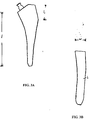
- Fig. 1 is a posterior view of a neutrally aligned prosthesis implanted within a femur.
- Fig. 2 is a posterior view of a mis-aligned prosthesis implanted within a femur.
- Fig. 3 is an anterior view of a left component of the inventive broach.
- Fig. 3A is an anterior view of a full broach used to construct the partial broach.
- Fig. 3B is a lateral view of the full broach illustrated in Fig. 3A.
- Fig. 4 is medial view of the inventive broach.
- Fig. 5 is a top plan view of the inventive broach.
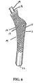
- Fig. 6 is an anterior view of a left component of the inventive broach illustrating the positioning of the preferred cutting teeth.
- Fig. 6A is an anterior view of the left component of another embodiment of the inventive broach illustrating the broach implanted within the medullary cavity of a femur.
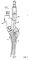
- Fig. 7 is an anterior view of the inventive machining assembly implanted within the medullary cavity of a femur.
- Fig. 8 is an anterior view of the assembled machining assembly, including a cutting instrument and broach.
- Figs. 9-11 are front, back, and side views, respectively, of the guide component of the machining assembly.
- Fig. 12 is a medial view of the machining assembly (without the broach and second cutting instrument).
- Fig. 13 is a cross-section view of the machining assembly taken along lines 13-13 of Fig. 12 illustrating the preferred means for securing the guide to the mounting block.
- Fig. 14 is a bottom plan view of the machining assembly (without the broach and second cutting instrument).
- Fig. 15 is a lateral view of the machining assembly (without the broach and second cutting instrument).
- Fig. 16 is an enlarged view of the spring plunger.
- Fig. 17 is an enlarged view of the locking screw for securing the guide to the mounting block.
- Fig. 18 is a longitudinal cross section view of the mounting block illustrating the various channels and bores.
- Fig. 19 is a side view of the machining assembly (without the broach and cutting instrument).
- Fig. 20 is a cross section view of the machining assembly taken along lines 20-20 of Fig. 19 illustrating the preferred means for securing the broach to the mounting block.
- Fig. 21 is a side view of the machining assembly.
- Fig. 22 is a cross-section view of the machining assembly taken along lines 22-22 of Fig. 21, wherein the locking assembly is shown in the home or retracted position to secure the broach within the mounting block.
- Fig. 23 is the cross-section view of the machining assembly as illustrated in Fig. 22, wherein the locking assembly is shown in the open position to allow insertion of the broach within the mounting block.
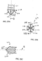
- Figs. 24A-24B are side views of the preferred second cutting instrument component of the machining assembly.
- Fig. 25A is an enlarged view of the distal tip of the second cutting instrument illustrated in Figs. 24A-24B.
- Figs. 25B is a bottom plan view of the second cutting instrument illustrated in Fig. 25B.
- Figs. 25C is a cross-section view of the distal tip taken along lines 25C-25C of Fig. 25B.
- the present invention is directed to an improved broach design and method for preparing the medullary cavity of a femur for subsequent implantation of a femoral prosthesis in hip arthroplasty.
- a femoral stem component of a hip prosthesis may then be implanted within the cavity, wherein the longitudinal axis of the stem is in neutral alignment with the medullary axis of the femur, resulting in improved rigid fixation of the stem, thereby minimizing the possibility of future loosening of the implant and pain associated with such loosening.
- neutral alignment refers to the substantial coincidence of longitudinal axes, specifically the medullary axis of the femur and the longitudinal axis of the broach or femoral prosthesis, as discussed in further detail below.
- Fig. 1 illustrates an undesirable implantation due to inaccurate broaching of the cavity where only partial contact is achieved between the stem (S) and the medullary cavity (C) (as shown in circled areas x and y).
- a problem that often occurs during conventional broaching/rasping is that the cutting instrument is deflected away from the hard bone of the greater trochanter (1), especially in the vicinity of the posterior margin of its medial wall (3), where the bone is generally very difficult to machine with conventional instruments, thereby altering the path of the instrument towards the softer adjacent bone at a site that is located more anteriorly and medially. As subsequent cutting instruments enlarge the initial point of entry, the bone is progressively removed from the anterior and medial walls of the cavity, leading to the development of a mis-aligned implantation site.
- the present invention is directed to a broach design and method for preparing the implantation site within the medullary cavity to allow for neutral alignment of a subsequently implanted femoral stem prosthesis, namely by employing a design that allows the broach to avoid the greater trochanter during initial broaching and preparation of the implantation site.
- the present invention comprises a partial broach (10) having a longitudinal axis (X), anterior (A), posterior (P), medial (M), and lateral (L) faces, a plurality of teeth (17) positioned on at least one the faces (shown in Figs. 6, 6A, and 7), and a lateral recess (13) positioned on the proximal segment (11) (i.e.
- the most preferred embodiment comprises a lateral recess (13) that extends from the anterior face (A) to the posterior face (P), as shown in the figures. It should be further noted that while the description of the invention and the related figures are directed to a left femoral broach, the present invention may also be designed for a right broach, which is merely a mirror image of the left broach described and illustrated herein.
- Figs. 3-6A illustrate a preferred configuration of the recess (13); however, alternative configurations of the recess may be employed, provided that each are of sufficient depth and proper placement to allow the broach to avoid the desired bony area, typically the greater trochanteric region of the femur.
- the base portion further includes a chamfer (15b) extending from the distal edge (16) to about point b and preferably positioned at an angle (6) of about 30 to about 60 degrees, most preferably about 45 degrees, relative to the longitudinal axis (X) of the broach.
- the chamfered edge (15b) of the recess is a preferred design feature that allows the broach (10) to avoid impingement against lateral bone beneath the greater trochanter, thereby minimizing the chance of a fracture upon extraction of the broach from the femur.
- the inventive broach comprises a plurality of cutting teeth (17) positioned on at least the medial face (M), but most preferably on all four faces of the broach (10).
- the configuration of the cutting teeth may be the same on all of the faces; however, the most preferred types and arrangement of cutting teeth are those shown in Fig. 6 as well as those described and illustrated in co-pending application Serial No. 08/594,892 and which is incorporated by reference herein in its entirety. While the preferred embodiment of the broach described in Serial No. 08/594,892 comprises a plurality of aggressively cutting diamond-shaped teeth on the lateral face, the presence of a lateral recess on the partial broach minimizes the need for aggressive cutting of lateral bone.
- the inventive partial broach is prepared from a "full" broach (i.e. one not having a lateral recess), as illustrated in Figs. 3A and 3B, whereby the recess portion is cut out of the full broach.
- the material is removed from the proximal lateral face of the broach such that the "length" of the recess (I 1 ) (see Figs. 3 and 3A) is from about 1.0 inch to about 1.2 inches, most preferably about 1.125 inches.
- the preferred depth (d) of the recess as illustrated in Fig.
- the inventive broach may be supplied in a range of different sizes to meet different surgical requirements.
- Table 2 lists preferred widths (w) and longitudinal lengths (I) for particular broach sizes.
- the width (w) values are obtained from a full broach (Figs 3B) measured from the anterior face to the posterior face.
- the neck (21) of the broach is positioned at an angle (7) relative to the broach's longitudinal axis (X) of about 36 degrees, as illustrated in Fig. 3.
- the overall configuration of the broach is the same as the configuration of the femoral prosthesis employed (except for the lateral recess).
- the figures illustrate an asymmetric design wherein the broach possesses a slight posterior bow, as best illustrated in Fig. 4.
- the inventive broach (10) is generally used in conjunction with a drill or awl (not shown) which is utilized to form an entry hole in the superior cortex of the femoral neck, preferably in the vicinity of the exit point (3) of the medullary axis (Y) (see Figs. 1 and 2).
- a detachable handle (not shown) is rigidly attached to the superior surface of the broach which is then driven into the femur (F) with a mallet or similar instrument.
- the broach As the broach is advanced down the femur, it will generally rotate until contact is achieved with the medial cortex proximally and the lateral femoral cortex just below the level of the lesser trochanter (2). If necessary, a succession of broaches or rasps of increasing size may be passed down the femur until a rigid fit is achieved at the appropriate position within the femur to allow optimal reconstruction of the femoral head center. At this point, an intimate fit will be achieved between the broach and the medullary cavity, and consequently the longitudinal axis (X) of the broach (10) and the medullary axis (Y) will substantially coincide (i.e. be in neutral alignment).
- a second finishing broach may be implanted in the femur to enlarge the implantation site to its final shape. Since generally the finishing broach is minimally larger than the inventive broach, with the exception of the recessed area, all of the energy delivered to the finishing broach can be utilized solely in removing bone in the medial aspect of the greater trochanter, which was initially avoided by the partial broach.
- the finishing broaches with cutting teeth of conventional diamond-shaped configuration can be readily implanted in a neutral orientation, provided that the implantation cavity has been initially prepared with the inventive broach.
- the inventive broach may also be used in combination with a machining device comprising a guide (200) configured to receive a second cutting instrument (208), the latter instrument being designed to machine additional bone initially avoided by the broach.
- Fig. 8 illustrates the preferred machine assembly comprising, in combination, the inventive broach (10) and a machining device comprising a mounting block (101), a guide (200), and a second cutting instrument (208).
- the machining assembly could include other types of cutting instruments in instead of the inventive partial broach for insertion within a bone cavity if desired for a particular procedure, including but not limited to, a full broach (e.g. Fig. 3A), rasp, reamer, and the like.
- a machining device including a guide (200) and a second cutting instrument (208) may be attached to the broach to remove additional bone initially avoided by the broach, as shown in Fig. 8, for example.
- the shape of the lateral recess (13) of the broach allows the second cutting instrument (208) to be advanced into the cavity (C) to machine away areas of the medial aspect of the greater trochanter (1) to enable insertion of a second broach, such as a finishing broach (not shown), or femoral prosthesis of similar shape as the inventive broach (except for the presence of a lateral recess).
- the machining assembly including the broach are removed from the femur.
- a prosthesis for example, of suitable shape designed to engage the machined cavity may be implanted in the femur (see Fig. 1, for example).
- a finishing broach with a shape similar to the inventive broach and the implantation site may be introduced into the femur to generate the final shape of the cavity and to remove discontinuities present between the areas of the femur that were in contact with the inventive broach and machined by the second cutting instrument (208).
- the machining assembly (100) comprises a guide (200) for receiving and directing the movement of the cutting instrument (208), more preferably including a means for securing the guide to a mounting block (101), and most preferably a means for allowing slidable engagement of the guide within the block (101) to permit multiple cutting positions relative to the block (101).
- the guide may be permanently attached to the mounting block or even directly to the broach by some other means of attachment.
- the guide (200) comprises a body (201) having an outer surface (201a) and an inner passage (203) communicating therethrough for receiving a second cutting instrument (208).
- the second cutting instrument (208) preferably includes a means for limiting the distance it may travel through the guide, preferably a collar (208a) affixed to the upper end of the instrument and which rests on the upper edge of the guide, for example as shown in Fig. 8.
- the cutting instrument is a cylindrical reamer which passes through a cylindrically-shaped guide, as illustrated in the figures; however, other means of machining bone are contemplated to be within the scope of the present invention, including, but not limited to, a hollow drill, a bone punch, or a chisel configured to match the shape of the recess.
- a preferred second cutting instrument (208) is a 90-degree point cutter as illustrated in Figs. 24A-24B and 25A-25C.
- the cutting instrument (208) comprises a body portion having preferably six flutes (211) and a distal tip (212) comprising a total of six cutting edges - two cutting edges (212a) converging into a point at a 90-degree angle (8) and four cutting edges (212b) terminating into a flat plane (212c) perpendicular to the longitudinal axis (Z) of the cutting instrument (208).
- the guide preferably includes an arm (202) which may be permanently secured to the mounting block; however, in the most preferred embodiment, the guide arm (202) is slidablely engaged within a complementary transverse chamber (205) passing through the block (Fig. 18). In this embodiment, the arm may be adjusted to different positions laterally for a desired cutting area, as discussed above.
- the machining assembly includes a means for securing the arm (202) within the chamber (205), preferably a locking screw (206) having a head (206a) and a lower body (206b) engaged within a complementary longitudinal bore (207) positioned on the superior end (102) of the block and in the communication with the transverse chamber (205).
- FIG. 17 illustrates an enlarged view of a locking screw design, wherein the lower body (206b) is further divided into four segments: a narrow segment (206c) subjacent the screw head (206a); a wide segment (206d) subjacent the narrow segment; an elongated segment (206e) subjacent the wide segment (206d); and a distal tip (209) having a diameter larger than the superior elongated segment (206e).
- a grooved pin (104) is employed which is contained within a complementary chamber (104a) communicating through the mounting block (101) adjacent the locking screw (206), as shown in Figs. 13, 18, and 19, for example.
- the guide arm (202) preferably includes a means for adjusting the guide at multiple positions relative to the mounting block, most preferably a plurality of indentations (204) positioned on the upper surface of the guide arm, and a spring biased plunger (300) engaged within a complementary longitudinal bore (302) parallel to the locking screw (206) and perpendicular to the transverse chamber (205).
- the plunger (300) includes a spring loaded lower resilient tip (301) which protrudes into the transverse chamber (205), such that when an indentation (204) is positioned directly beneath the plunger, the lower tip (301) engages the indentation (204).
- the indentations are spaced apart from each other at desired intervals corresponding to different size broaches that may be employed during the surgical procedure.
- the guide (200) illustrated in Figs. 9-11 comprises two indentations spaced apart to correspond to two different broach sizes (i.e. No. 4 and No. 5 broaches).
- the sizes are engraved on the guide arm (202) and can be viewed by the surgeon through an opening (105) in the block.
- the preferred configuration is one having at least three flat sides that correspond to a transverse chamber (205) having at least three corresponding sides to prevent rotational movement of the arm about a transverse axis (210) defined within the chamber (205).
- the most preferred embodiment as illustrated in the figures comprises six sides (202b) arranged as illustrated in Figs. 9-11 for greater engagement and wear.
- the inventive machining assembly (100) further includes a means for securing a broach to the mounting block (101). While other conventional locking means known by those of ordinary skill in the art may be employed, the figures illustrate a preferred locking mechanism which includes a bore (400) present in the inferior end (103) of the block and configured for receiving a boss or trunion (18) positioned on the superior end (12) of the broach.
- a locking pin assembly comprising a spring biased push pin (401) engaged within a first complementary transverse chamber (402) positioned above the bore (400), a locking pin (403) engaged within a second complementary transverse chamber (404) parallel to the first chamber (402) and in communication with the bore (400), wherein the second chamber (404) is positioned between the bore (400) and the first chamber (401), and a connecting piece (405) securing one end of the locking pin (403) to an end of the push pin (401).
- the push pin (401) is housed within a helical spring (401a) having a sufficiently high compression to ensure stability of the locking system. As illustrated in Figs.
- the locking pin (403) when the spring pin (401) is actuated (i.e. pushed in the direction of the arrow), the locking pin (403) is disengaged from its corresponding transverse chamber (404) to allow entry of the broach's boss or trunion (18) into the bore (400) (Fig. 22). Upon subsequent release of the push pin (401), the locking pin (403) re-enters the bore (400) to lock the boss (18) therein, thereby securing the broach to the mounting block (101) (Fig. 23).
- the locking pin (403) is tapered to slide into, and be received by, a corresponding notch (19) positioned on the trunion or boss (18).
- the mounting block may also include a small key member (406) (Figs. 14-15, and 18) that extends downward below the bore (400) and is configured to engage a complementary groove (20) positioned on the superior end (12) of the broach adjacent the trunion or boss (18), as illustrated in Fig. 5, for example. Engagement of the key member (406) within the groove (20) functions to prevent any rotational movement of the mounting block (101) about the longitudinal axis (X) of the broach (10).
- a small key member (406) (Figs. 14-15, and 18) that extends downward below the bore (400) and is configured to engage a complementary groove (20) positioned on the superior end (12) of the broach adjacent the trunion or boss (18), as illustrated in Fig. 5, for example. Engagement of the key member (406) within the groove (20) functions to prevent any rotational movement of the mounting block (101) about the longitudinal axis (X) of the broach (10).
- the present invention is particularly advantageous in the preparation of a femoral medullary cavity for receipt of a femoral prosthesis whereby upon subsequent implantation of the prosthesis, the longitudinal axis of the prosthesis substantially coincides with the medullary axis, thereby achieving neutral alignment within the cavity for more rigid fixation and stability.
- One method of preparing the desired implantation site is to drive the partial broach into the medullary cavity as described above in Section II. Once the medullary cavity has been prepared using the partial broach, a second finishing broach that does not contain a lateral recess may then be used to enlarge the implantation site to its final shape as well as remove bone in the medial aspect of the greater trochanter.
- Fig. 7 illustrates the machining assembly (100) implanted within the medullary cavity (C) of a femur (F).
- the mounting block (101) having lateral (L 1 ) and medial (M 1 ) sides is secured to the trunion (18) by means of the locking pin assembly described above.
- the guide (200) is then secured within the transverse chamber (205) and placed on the lateral side (L 1 ) of the mounting block over the recessed area (13) of the broach (10) at a position corresponding to the desired broach size.
- the second cutting instrument (208) is then placed within the guide and advanced into the recessed cavity, preferably by means of a straight plunge, to machine away areas of the medial aspect of the greater trochanter to enable insertion of another broach or prosthesis of similar shape to the inventive partial broach (but without having the lateral recess). Once the second cutting instrument (208) is advanced to the base portion of the recess (i.e.
- the cutting instrument (208) may be withdrawn from the recess, the guide transferred to a new position, and then the cutting instrument (208) is again advanced to the maximum possible depth (i.e. the base of the recess). This process may be repeated until all bone within the recess has been removed.
- a side cutting reamer (not shown) may be advanced through the guide and then moved along a curved track in a side-cutting manner until all bone has been removed.
- the description of the design and use of the inventive machining assembly has been confined to the preferred method of use, namely in preparing the femoral medullary cavity to receive a femoral prosthesis during hip arthroplasty.
- the machining assembly includes the inventive partial broach described herein, it possible to prepare a medullary cavity that allows for the subsequent implantation of a neutrally aligned femoral stem component. It is contemplated, however, that one of ordinary skill in the art, having the benefit of the invention's teachings and suggestions, could make any necessary modifications to the machining assembly, including the broach, for other orthopedic surgical procedures requiring the removal of bone.
- the preferred materials for fabricating the components of the machining assembly are those typically employed in orthopedic surgical instruments and implants, including, but not limited to, stainless steels and alloys of cobalt, chromium, and molybdenum. Preferred materials include 455 and 17-4 precipitated hardenable stainless steels.
- the outer surface of the second cutting instrument employed within the guide is preferably electropolished and coated with a chromium nitride or similar surface hardening compound.
Landscapes
- Health & Medical Sciences (AREA)
- Surgery (AREA)
- Life Sciences & Earth Sciences (AREA)
- Biomedical Technology (AREA)
- Medical Informatics (AREA)
- Orthopedic Medicine & Surgery (AREA)
- Oral & Maxillofacial Surgery (AREA)
- Engineering & Computer Science (AREA)
- Dentistry (AREA)
- Heart & Thoracic Surgery (AREA)
- Nuclear Medicine, Radiotherapy & Molecular Imaging (AREA)
- Molecular Biology (AREA)
- Animal Behavior & Ethology (AREA)
- General Health & Medical Sciences (AREA)
- Public Health (AREA)
- Veterinary Medicine (AREA)
- Surgical Instruments (AREA)
- Prostheses (AREA)
Abstract
Description
| Broach size | Depth (d) (inches) | Radius (inches) |
| No. 2 | 0.897 | 0.500 |
| No. 3 | 1.010 | 0.500 |
| No. 4 | 1.120 | 0.625 |
| No. 5 | 1.221 | 0.500 |
| No. 6 | 1.290 | 0.625 |
| No. 7 | 1.283 | 0.625 |
| No. 8 | 1.277 | 0.625 |
| Broach size | Length (I1) (inches) | Width (w) (inches) |
| No. 2 | 4.699 | 0.704 |
| No. 3 | 4.863 | 0.757 |
| No. 4 | 5.019 | 0.827 |
| No. 5 | 5.164 | 0.878 |
| No. 6 | 5.395 | 0.949 |
| No. 7 | 5.347 | 1.002 |
| No. 8 | 5.667 | 1.068 |
Claims (32)
- A machining assembly suitable for use in preparing a bone cavity for subsequent implantation of a prosthesis, said assembly comprising:a first bone cutting instrument (10) designed for placement within a bone cavity to prepare said bone cavity for implantation of a prosthesis (S), said instrument comprising a superior end (12);a mounting block (101) secured to said first cutting instrument (10);a guide (200) secured to said mounting block (101) and configured to receive a second bone cutting instrument (208); anda second bone cutting instrument (208) carried within said guide (200), said second bone cutting instrument (208) designed to remove additional bony material after placement of said first bone cutting instrument within said cavity and prior to implantation of said prosthesis within said prepared bone cavity.
- The machining assembly of claim 1, wherein said guide (200) further comprises (a) a body (201) having an outer surface (201A) and an inner passage (203) communicating therethrough to accommodate said second bone cutting instrument (208) and (b) a guide arm (202) integral with said outer surface of said body and secured to said mounting block (101).
- The machining assembly of claim 2, further including a means for securing said guide to said mounting block, said securing means including an inner transverse chamber (205) contained within said mounting block (101) and communicating therethrough, wherein said chamber is configured for slidable engagement of said guide arm (202) therein.
- The machining assembly of claim 3, wherein said means for securing said guide to said mounting block further includes a locking screw (206) having a head (206a) and a lower body (206b) engaged within a first complementary longitudinal bore (207) positioned on the superior end (102) of the block, said bore in communication with said transverse chamber (205);
whereby when said locking screw is turned in one direction, the lower body of the screw achieves contact with said guide arm to preclude sliding movement of said arm within the chamber, and when said screw is turned in an opposite direction, said lower body of the screw is retracted to release said arm, thereby permitting slidable movement of the guide arm within the transverse chamber. - The machining assembly of claim 4, wherein said guide arm (202) and said transverse chamber (205) are configured to prevent rotational movement of said guide arm about a transverse axis (210) defined within said chamber.
- The machining assembly of claim 3, wherein said guide further includes a means for adjusting the guide at multiple positions relative to said mounting block, said adjusting means including an indentation (204) positioned on said guide arm and a spring biased plunger (300) engaged in a second complementary bore (302) parallel with said locking screw (206) and perpendicular to said transverse chamber (205), said plunger having a lower tip (301) protruding into said chamber;
whereby when said indentation is positioned beneath said plunger, the lower tip is engaged within said indentation. - The machining assembly of claim 1, further a means for securing said first bone cutting instrument to said mounting block, said securing means including:whereby when said spring biased pin is actuated, said locking pin is disengaged from said second transverse chamber to allow entry of said boss into said first bore, and whereby upon subsequent release of said spring biased pin, said locking pin is engaged within said first bore to lock said boss of said first bone cutting instrument therein.(a) a first bore (400) configured to receive a boss (18) positioned on said superior end (12) of said first bone cutting instrument (10); and(b) a locking pin assembly comprising a spring biased pin (401) engaged within a first complementary transverse chamber (402) positioned above said first bore (400), a locking pin (403) engaged within a second complementary transverse chamber (404) parallel to said first transverse chamber and positioned between said first chamber and first bore, said second transverse chamber being in communication with said first bore; and a means for connecting said locking pin to said spring biased pin;
- The machining assembly of claim 7, wherein said locking pin (403) has a tapered end.
- The machining assembly of claim 7, wherein said boss (18) includes a notch (19) configured to receive said locking pin (403) for rigid fixation of said first bone cutting instrument within said first bore (400).
- The machining assembly of claim 7, wherein said inferior end (103) of said mounting block (101) has a key member (406) extending downward below said first bore (400) and configured to engage a complementary groove (20) located on said superior end (12)of said first bone cutting instrument adjacent said boss; whereby when said boss is rigidly engaged within said first bore of said mounting block, said key member is engaged within said groove to preclude rotational movement of said mounting block about the longitudinal axis (X) of said first bone cutting instrument.
- The machining assembly of claim 3, further a means for securing said first bone cutting instrument to said mounting block, said securing means including:whereby when said spring biased pin is actuated, said locking pin is disengaged from said second transverse chamber to allow entry of said boss into said first bore, and whereby upon subsequent release of said spring biased pin, said locking pin is engaged within said first bore to lock said boss of said first bone cutting instrument therein.(a) a first bore (400) configured to receive a boss (18) positioned on said superior end (13) of said first bone cutting instrument (10); and(b) a locking pin assembly comprising a spring biased pin (401) engaged within a first complementary transverse chamber (402) positioned above said first bore (400), a locking pin (403) engaged within a second complementary transverse chamber (404) parallel to said first transverse chamber (402) and positioned between said first chamber and first bore, said second transverse chamber being in communication with said first bore; and a means for connecting said locking pin to said spring biased pin;
- A machining assembly suitable for use in preparing a medullary cavity of a femur for subsequent implantation of a femoral prosthesis, said assembly comprising:a femoral broach (10) designed for placement within a medullary cavity (C) of a femur to prepare said cavity for implantation of a femoral prosthesis, said broach comprising a longitudinal axis (X); anterior (A), posterior (P), medial (M), and lateral (L) faces; a plurality of cutting teeth (17) positioned on at least one of said faces; a proximal segment including said faces and having a superior end (12) and a recess (13) positioned on said lateral face of said proximal segment and extending downward from said superior end, said recess configured to avoid the greater trochanteric bone upon implantation of said broach within said cavity;a guide (200) secured to said broach and configured to receive a second bone cutting instrument (208); anda second bone cutting instrument (208) carried within said guide (200) for removing additional bone from said femur prior to implantation of said femoral prosthesis within said prepared cavity.
- The machining assembly of claim 12, wherein said recess (13) extends from said posterior (P) face to said anterior (A) face.
- The machining assembly of claim 13, wherein said recess (13) includes a back portion (14) and a base portion (15).
- The machining assembly of claim 14, wherein said base portion comprises a concavity (15a) having a distal edge (16).
- The machining assembly of claim 15, wherein said recess further includes a chamfer (15b) extending downward from said distal edge (16) of said concavity (15a).
- The machining assembly of claim 12, further including a mounting block (101) having a superior end (102), wherein said guide (200) further comprises a (a) body (203) having an outer surface (201a) and an inner passage (203) communicating therethrough to accommodate said second bone cutting instrument (208) and (b) a guide arm (202) integral with said outer surface of said body and secured to said mounting block.
- The machining assembly of claim 17, further including a means for securing said guide (200) to said mounting block (101), said securing means including an inner transverse chamber (205) contained within said mounting block and communicating therethrough, wherein said chamber is configured for slidable engagement of said guide arm therein.
- The machining assembly of claim 18, wherein said means for securing said guide to said mounting block further includes a locking screw (206) having a head (206a) and a lower body (206b) engaged within a first complementary longitudinal bore (207) positioned on the superior end of the block, said bore in communication with said transverse chamber (205);
whereby when said locking screw is turned in one direction, the lower body of the screw achieves contact with said guide arm to preclude sliding movement of said arm within the chamber, and when said screw is turned in an opposite direction, said lower body of the screw is retracted to release said arm, thereby permitting slidable movement of the guide arm within the transverse chamber. - The machining assembly of claim 18, wherein said guide further includes a means for adjusting the guide at multiple positions relative to said mounting block, said adjusting means including an indentation positioned on said guide arm (202) and a spring biased plunger (300) engaged in a second complementary bore (302) parallel with said locking screw (206) and perpendicular to said transverse chamber (205), said plunger having a lower tip (301) protruding into said chamber, whereby when said indentation is positioned beneath said plunger, the lower tip is engaged within said indentation.
- The machining assembly of claim 12, further including a mounting block (101) having an inferior end (103) and a means for securing said broach to said mounting block, said securing means including:whereby when said spring biased pin is actuated, said locking pin is disengaged from said second transverse chamber to allow entry of said boss into said first bore, and whereby upon subsequent release of said spring biased pin, said locking pin is engaged within said first bore to lock said boss of said broach therein.(a) a first bore (400) configured to receive a boss (18) positioned on the superior end (12) of said broach (10); and(b) a locking pin assembly comprising a spring biased pin (401) engaged within a first complementary transverse chamber (402) positioned above said first bore (400), a locking pin (403) engaged within a second complementary transverse chamber (404) parallel to said first transverse chamber and positioned between said first chamber and first bore, said second transverse chamber being in communication with said first bore; and a means for connecting said locking pin to said spring biased pin;
- The machining assembly of claim 21, wherein said locking pin (403) has a tapered end.
- The machining assembly of claim 22, wherein said boss (18) includes a notch (19) configured to receive said locking pin (403) for rigid fixation of said broach within said first bore.
- The machining assembly of claim 23, wherein said inferior end (103) of said mounting block has a key member (406) extending downward below said first bore and configured to engage a complementary groove (20) located on said superior end of said broach adjacent said boss;
whereby when said boss is rigidly engaged within said first bore of said mounting block, said key member is engaged within said groove to preclude rotational movement of said mounting block about a longitudinal axis (X) of said broach. - A method of implanting a femoral stem prosthesis into a femur, said method comprising the steps of:(a) preparing a femoral medullary cavity (C) for implantation of a femoral prosthesis by first driving a broach (10) into the medullary cavity (C) until said broach is in neutral alignment within said cavity, wherein said broach comprises a longitudinal axis (X); anterior (A), posterior (P), medial (M), and lateral (L) faces; a plurality of cutting teeth (17) positioned on at least one of said faces; a proximal segment (11) including said faces and having a superior end (12) and a recess (13) positioned on said lateral face (L) of said proximal segment and extending downward from said superior end, said recess configured to avoid the greater trochanteric bone upon implantation of said broach within said cavity;(b) attaching a bone machining device to said broach, said device comprising:a guide (200) secured to said broach and configured to receive a second bone cutting instrument (208); anda second bone cutting instrument (208) carried within said guide and suitable for removing bone from said femur;(c) removing additional bone from said femur with said second bone cutting instrument;(d) removing said machining device and broach from said medullary cavity; and(e) implanting said femoral prosthesis (S) into the prepared medullary cavity (C), wherein a longitudinal axis (Y1) of said prosthesis substantially coincides with the femoral medullary axis (Y) for neutral alignment of the prosthesis therein.
- The method of claim 25, wherein said step of removing additional bone includes removing greater trochanteric bone from said femur with said second bone cutting instrument to allow passage of said femoral prosthesis into the prepared medullary cavity
- The method of claim 25, wherein said guide is secured to said broach by means of a mounting block (101) attached to said broach (10), said block having lateral (L1) and medial (M1) sides.
- The method of claim 27, wherein said second cutting instrument (208) is positioned on said lateral side (L1) of said mounting block (101), and said step of removing additional bone includes removing greater trochanteric bone from said femur with said second bone cutting instrument to allow passage of a femoral component into the prepared medullary cavity.
- The method of claim 25, wherein after step "d", further including the step of driving a second finishing broach into the medullary cavity to enlarge said cavity to a final desired shape.
- A machining assembly suitable for use in preparing a medullary cavity of a femur for subsequent implantation of a femoral prosthesis, said assembly comprising:a mounting block (101);a femoral broach (10) designed for placement within the medullary cavity (C) of a femur to prepare said cavity for implantation of a femoral prosthesis (S), said broach comprising a longitudinal axis (X); anterior (A), posterior (P), medial (M), and lateral (L) faces; a plurality of cutting teeth positioned on at least one of said faces; a proximal segment (11) including said faces and having a superior end (12) and a recess (13) positioned on said lateral face (L) of said proximal segment and extending downward from said superior end, said recess configured to avoid the greater trochanteric bone upon implantation of said broach within said cavity;a means for securing said broach to said mounting block (101);a guide (200) configured to receive a second bone cutting instrument (208);a means for securing said guide to said mounting block; anda second bone cutting instrument (208) carried within said guide (200) for removing additional bone from said femur prior to implantation of said femoral prosthesis within said prepared cavity.
- The machining assembly of claim 30, wherein said broach recess (13) extends from said posterior face (P) to said anterior face (A), said recess further including a back portion (14) and a base portion (15).
- The machining assembly of claim 31, wherein said base portion (15) comprises a concavity (15a) having a distal edge (16), said recess further including a chamfer (15b) extending downward from said distal edge (16) of said concavity (C).
Applications Claiming Priority (2)
| Application Number | Priority Date | Filing Date | Title |
|---|---|---|---|
| US749279 | 1996-11-13 | ||
| US08/749,279 US5810830A (en) | 1996-11-13 | 1996-11-13 | Machining assembly and methods for preparing the medullary cavity of a femur in hip arthroplasty |
Publications (3)
| Publication Number | Publication Date |
|---|---|
| EP0842639A2 true EP0842639A2 (en) | 1998-05-20 |
| EP0842639A3 EP0842639A3 (en) | 1998-06-10 |
| EP0842639B1 EP0842639B1 (en) | 2004-02-25 |
Family
ID=25013072
Family Applications (1)
| Application Number | Title | Priority Date | Filing Date |
|---|---|---|---|
| EP97308809A Expired - Lifetime EP0842639B1 (en) | 1996-11-13 | 1997-11-03 | Machining assembly for preparing the medullary cavity of a femur in hip arthroplasty |
Country Status (7)
| Country | Link |
|---|---|
| US (1) | US5810830A (en) |
| EP (1) | EP0842639B1 (en) |
| JP (1) | JP3324972B2 (en) |
| AT (1) | ATE260073T1 (en) |
| AU (1) | AU736610B2 (en) |
| CA (1) | CA2219163C (en) |
| DE (1) | DE69727767T2 (en) |
Cited By (12)
| Publication number | Priority date | Publication date | Assignee | Title |
|---|---|---|---|---|
| US6482209B1 (en) | 2001-06-14 | 2002-11-19 | Gerard A. Engh | Apparatus and method for sculpting the surface of a joint |
| US6723102B2 (en) | 2001-06-14 | 2004-04-20 | Alexandria Research Technologies, Llc | Apparatus and method for minimally invasive total joint replacement |
| US7785328B2 (en) | 2003-12-30 | 2010-08-31 | Depuy Products, Inc. | Minimally invasive bone miller apparatus |
| US8419799B2 (en) | 2003-06-25 | 2013-04-16 | Depuy Products, Inc. | Assembly tool for modular implants and associated method |
| US8597298B2 (en) | 2006-09-29 | 2013-12-03 | DePuy Synthes Products, LLC | Proximal reamer |
| US8685036B2 (en) | 2003-06-25 | 2014-04-01 | Michael C. Jones | Assembly tool for modular implants and associated method |
| US8998919B2 (en) | 2003-06-25 | 2015-04-07 | DePuy Synthes Products, LLC | Assembly tool for modular implants, kit and associated method |
| US9095452B2 (en) | 2010-09-01 | 2015-08-04 | DePuy Synthes Products, Inc. | Disassembly tool |
| US9101495B2 (en) | 2010-06-15 | 2015-08-11 | DePuy Synthes Products, Inc. | Spiral assembly tool |
| US9119601B2 (en) | 2007-10-31 | 2015-09-01 | DePuy Synthes Products, Inc. | Modular taper assembly device |
| US9717545B2 (en) | 2007-10-30 | 2017-08-01 | DePuy Synthes Products, Inc. | Taper disengagement tool |
| US10064725B2 (en) | 2011-04-06 | 2018-09-04 | DePuy Synthes Products, Inc. | Distal reamer for use during an orthopaedic surgical procedure to implant a revision hip prosthesis |
Families Citing this family (51)
| Publication number | Priority date | Publication date | Assignee | Title |
|---|---|---|---|---|
| GB9714004D0 (en) * | 1997-07-02 | 1997-09-10 | Howmedica | Apparatus for releasably attaching an impaction hammer to a proximal impactor to be impacted into a bone |
| US20070173858A1 (en) * | 2001-06-14 | 2007-07-26 | Alexandria Research Technologies, Llc | Apparatus and Method for Sculpting the Surface of a Joint |
| US8801720B2 (en) | 2002-05-15 | 2014-08-12 | Otismed Corporation | Total joint arthroplasty system |
| US7854737B2 (en) * | 2002-12-20 | 2010-12-21 | Depuy Products, Inc. | Instrument and associated method of trailing for modular hip stems |
| US20040122439A1 (en) * | 2002-12-20 | 2004-06-24 | Dwyer Kimberly A. | Adjustable biomechanical templating & resection instrument and associated method |
| US7022141B2 (en) * | 2002-12-20 | 2006-04-04 | Depuy Products, Inc. | Alignment device for modular implants and method |
| US7235106B2 (en) * | 2002-12-20 | 2007-06-26 | Depuy Products, Inc. | Modular hip stems and associated method of trialing |
| US7001392B2 (en) * | 2003-01-29 | 2006-02-21 | Howmedica Osteonics Corp. | Apparatus and method for preparing bone for antirotational implantation of an orthopedic endoprosthesis |
| US20040249384A1 (en) * | 2003-02-04 | 2004-12-09 | Blaha J. David | Compacting broach |
| US20040267267A1 (en) * | 2003-06-25 | 2004-12-30 | Daniels David Wayne | Non-linear reamer for bone preparation and associated method |
| US7074224B2 (en) | 2003-06-25 | 2006-07-11 | Depuy Products, Inc. | Modular tapered reamer for bone preparation and associated method |
| US8657824B2 (en) * | 2003-11-18 | 2014-02-25 | Smith & Nephew, Inc. | Universal double offset surgical instrument |
| ES2331520T3 (en) * | 2003-11-18 | 2010-01-07 | SMITH & NEPHEW, INC. | SURGICAL TECHNIQUE AND INSTRUMENTATION FOR A HIP SURGERY BY HUMANBAR WITH MINIMUM INCISION. |
| DE602004026400D1 (en) * | 2004-02-24 | 2010-05-20 | Lafarge Platres | Method and device for producing a hydraulically set pore body |
| US7582090B2 (en) * | 2004-03-04 | 2009-09-01 | Wright Medical Technology, Inc. | Bone preserving total hip arthroplasty using autograft |
| US7507242B2 (en) * | 2004-06-02 | 2009-03-24 | Facet Solutions | Surgical measurement and resection framework |
| US20060264951A1 (en) | 2005-05-18 | 2006-11-23 | Nelson Charles L | Minimally Invasive Actuable Bone Fixation Devices Having a Retractable Interdigitation Process |
| US9060820B2 (en) | 2005-05-18 | 2015-06-23 | Sonoma Orthopedic Products, Inc. | Segmented intramedullary fracture fixation devices and methods |
| US8287539B2 (en) | 2005-05-18 | 2012-10-16 | Sonoma Orthopedic Products, Inc. | Fracture fixation device, tools and methods |
| US8961516B2 (en) | 2005-05-18 | 2015-02-24 | Sonoma Orthopedic Products, Inc. | Straight intramedullary fracture fixation devices and methods |
| US9808262B2 (en) | 2006-02-15 | 2017-11-07 | Howmedica Osteonics Corporation | Arthroplasty devices and related methods |
| EP2007291A2 (en) | 2006-02-15 | 2008-12-31 | Otismed Corp. | Arthroplasty jigs and related methods |
| US7935125B2 (en) | 2006-03-06 | 2011-05-03 | Howmedica Osteonics Corp. | Compound offset handle |
| US20080033444A1 (en) * | 2006-03-06 | 2008-02-07 | Howmedica Osteonics Corp. | Compound offset handle |
| JP2010510040A (en) | 2006-11-22 | 2010-04-02 | ソノマ・オーソペディック・プロダクツ・インコーポレイテッド | Fracture fixation device, tool and method |
| US8460302B2 (en) | 2006-12-18 | 2013-06-11 | Otismed Corporation | Arthroplasty devices and related methods |
| WO2008124818A2 (en) * | 2007-04-10 | 2008-10-16 | Intelifuse, Inc. | System and guide for directing surgical drills |
| USD642263S1 (en) | 2007-10-25 | 2011-07-26 | Otismed Corporation | Arthroplasty jig blank |
| US8460303B2 (en) | 2007-10-25 | 2013-06-11 | Otismed Corporation | Arthroplasty systems and devices, and related methods |
| US10582934B2 (en) | 2007-11-27 | 2020-03-10 | Howmedica Osteonics Corporation | Generating MRI images usable for the creation of 3D bone models employed to make customized arthroplasty jigs |
| US8737700B2 (en) | 2007-12-18 | 2014-05-27 | Otismed Corporation | Preoperatively planning an arthroplasty procedure and generating a corresponding patient specific arthroplasty resection guide |
| US8311306B2 (en) | 2008-04-30 | 2012-11-13 | Otismed Corporation | System and method for image segmentation in generating computer models of a joint to undergo arthroplasty |
| US8480679B2 (en) * | 2008-04-29 | 2013-07-09 | Otismed Corporation | Generation of a computerized bone model representative of a pre-degenerated state and useable in the design and manufacture of arthroplasty devices |
| US8777875B2 (en) | 2008-07-23 | 2014-07-15 | Otismed Corporation | System and method for manufacturing arthroplasty jigs having improved mating accuracy |
| US8715291B2 (en) | 2007-12-18 | 2014-05-06 | Otismed Corporation | Arthroplasty system and related methods |
| US8160345B2 (en) | 2008-04-30 | 2012-04-17 | Otismed Corporation | System and method for image segmentation in generating computer models of a joint to undergo arthroplasty |
| US8545509B2 (en) | 2007-12-18 | 2013-10-01 | Otismed Corporation | Arthroplasty system and related methods |
| US8617171B2 (en) | 2007-12-18 | 2013-12-31 | Otismed Corporation | Preoperatively planning an arthroplasty procedure and generating a corresponding patient specific arthroplasty resection guide |
| US8221430B2 (en) | 2007-12-18 | 2012-07-17 | Otismed Corporation | System and method for manufacturing arthroplasty jigs |
| US8734455B2 (en) | 2008-02-29 | 2014-05-27 | Otismed Corporation | Hip resurfacing surgical guide tool |
| US8617175B2 (en) | 2008-12-16 | 2013-12-31 | Otismed Corporation | Unicompartmental customized arthroplasty cutting jigs and methods of making the same |
| JP5255956B2 (en) * | 2008-09-01 | 2013-08-07 | 京セラメディカル株式会社 | Broach and method for manufacturing broach |
| AU2009296243A1 (en) | 2008-09-26 | 2010-04-01 | Sonoma Orthopedic Products, Inc. | Bone fixation device, tools and methods |
| US8167882B2 (en) | 2008-09-30 | 2012-05-01 | Depuy Products, Inc. | Minimally invasive bone miller apparatus |
| US9265542B2 (en) * | 2012-06-27 | 2016-02-23 | DePuy Synthes Products, Inc. | Variable angle bone fixation device |
| US9402637B2 (en) | 2012-10-11 | 2016-08-02 | Howmedica Osteonics Corporation | Customized arthroplasty cutting guides and surgical methods using the same |
| US10667798B2 (en) | 2012-10-29 | 2020-06-02 | Zimmer, Inc. | Surgical tool handle assemblies and related methods |
| US9770278B2 (en) | 2014-01-17 | 2017-09-26 | Arthrex, Inc. | Dual tip guide wire |
| US9814499B2 (en) | 2014-09-30 | 2017-11-14 | Arthrex, Inc. | Intramedullary fracture fixation devices and methods |
| CN110882034B (en) * | 2019-12-25 | 2024-05-14 | 陕西四正医疗器械有限责任公司 | Intramedullary cavity rasping and pulling device |
| US11602359B2 (en) | 2020-01-24 | 2023-03-14 | Zimmer, Inc. | Rasp handle adapter |
Citations (4)
| Publication number | Priority date | Publication date | Assignee | Title |
|---|---|---|---|---|
| US4738256A (en) | 1985-06-26 | 1988-04-19 | Finsbury (Instruments) Limited | Surgical tool |
| US4777942A (en) | 1986-10-02 | 1988-10-18 | Sulzer Brothers Limited | Bone milling instrument |
| US4809689A (en) | 1985-10-28 | 1989-03-07 | Mecron Medizinische Produkte Gmbh | Drilling system for insertion of an endoprosthesis |
| US5169402A (en) | 1988-10-08 | 1992-12-08 | Chas. F. Thackray Ltd. | Surgical instrument |
Family Cites Families (10)
| Publication number | Priority date | Publication date | Assignee | Title |
|---|---|---|---|---|
| US4306550A (en) * | 1980-02-06 | 1981-12-22 | Minnesota Mining And Manufacturing Company | Combination including femoral rasp and calcar facing reamer |
| US4601289A (en) * | 1985-04-02 | 1986-07-22 | Dow Corning Wright | Femoral trial prosthesis/rasp assembly |
| US4765328A (en) * | 1987-08-10 | 1988-08-23 | Osteonics Corp. | Surgical instrument handle coupling |
| GB9026592D0 (en) * | 1990-12-06 | 1991-01-23 | Meswania Jayantilal M | Surgical instrument |
| US5169401A (en) * | 1991-12-20 | 1992-12-08 | Zimmer, Inc. | Surgical reamer assembly |
| WO1994012123A1 (en) * | 1992-11-20 | 1994-06-09 | Burke Dennis W | Improved femoral implant collar and installation apparatus |
| US5342363A (en) * | 1992-11-30 | 1994-08-30 | Wright Medical Technology, Inc. | Medical instrument and procedure |
| ES2125449T3 (en) * | 1993-05-27 | 1999-03-01 | Howmedica | FLEXIBLE SYSTEM TO WIDEN THE SPINAL CHANNEL. |
| US5468243A (en) * | 1993-10-27 | 1995-11-21 | Halpern; Alan A. | Femoral superior neck remodelling means and method |
| US5534005A (en) * | 1994-10-05 | 1996-07-09 | Smith & Nephew Richards, Inc. | Surgical milling system |
-
1996
- 1996-11-13 US US08/749,279 patent/US5810830A/en not_active Expired - Lifetime
-
1997
- 1997-10-24 CA CA002219163A patent/CA2219163C/en not_active Expired - Fee Related
- 1997-11-03 DE DE69727767T patent/DE69727767T2/en not_active Expired - Fee Related
- 1997-11-03 EP EP97308809A patent/EP0842639B1/en not_active Expired - Lifetime
- 1997-11-03 AT AT97308809T patent/ATE260073T1/en not_active IP Right Cessation
- 1997-11-12 AU AU45286/97A patent/AU736610B2/en not_active Ceased
- 1997-11-13 JP JP31188197A patent/JP3324972B2/en not_active Expired - Fee Related
Patent Citations (4)
| Publication number | Priority date | Publication date | Assignee | Title |
|---|---|---|---|---|
| US4738256A (en) | 1985-06-26 | 1988-04-19 | Finsbury (Instruments) Limited | Surgical tool |
| US4809689A (en) | 1985-10-28 | 1989-03-07 | Mecron Medizinische Produkte Gmbh | Drilling system for insertion of an endoprosthesis |
| US4777942A (en) | 1986-10-02 | 1988-10-18 | Sulzer Brothers Limited | Bone milling instrument |
| US5169402A (en) | 1988-10-08 | 1992-12-08 | Chas. F. Thackray Ltd. | Surgical instrument |
Cited By (23)
| Publication number | Priority date | Publication date | Assignee | Title |
|---|---|---|---|---|
| US7896922B2 (en) | 2001-06-14 | 2011-03-01 | Alexandria Research Technologies, Llc | Implants for partial knee arthroplasty |
| US6723102B2 (en) | 2001-06-14 | 2004-04-20 | Alexandria Research Technologies, Llc | Apparatus and method for minimally invasive total joint replacement |
| US6482209B1 (en) | 2001-06-14 | 2002-11-19 | Gerard A. Engh | Apparatus and method for sculpting the surface of a joint |
| US8685036B2 (en) | 2003-06-25 | 2014-04-01 | Michael C. Jones | Assembly tool for modular implants and associated method |
| US8419799B2 (en) | 2003-06-25 | 2013-04-16 | Depuy Products, Inc. | Assembly tool for modular implants and associated method |
| US8998919B2 (en) | 2003-06-25 | 2015-04-07 | DePuy Synthes Products, LLC | Assembly tool for modular implants, kit and associated method |
| US9381097B2 (en) | 2003-06-25 | 2016-07-05 | DePuy Synthes Products, Inc. | Assembly tool for modular implants, kit and associated method |
| US7785328B2 (en) | 2003-12-30 | 2010-08-31 | Depuy Products, Inc. | Minimally invasive bone miller apparatus |
| US8597298B2 (en) | 2006-09-29 | 2013-12-03 | DePuy Synthes Products, LLC | Proximal reamer |
| US8852189B2 (en) | 2006-09-29 | 2014-10-07 | DePuy Synthes Products, LLC | Proximal reamer |
| US8852188B2 (en) | 2006-09-29 | 2014-10-07 | DePuy Synthes Products, LLC | Proximal reamer |
| US9717545B2 (en) | 2007-10-30 | 2017-08-01 | DePuy Synthes Products, Inc. | Taper disengagement tool |
| US9119601B2 (en) | 2007-10-31 | 2015-09-01 | DePuy Synthes Products, Inc. | Modular taper assembly device |
| US10166118B2 (en) | 2010-06-15 | 2019-01-01 | DePuy Synthes Products, Inc. | Spiral assembly tool |
| US9101495B2 (en) | 2010-06-15 | 2015-08-11 | DePuy Synthes Products, Inc. | Spiral assembly tool |
| US9095452B2 (en) | 2010-09-01 | 2015-08-04 | DePuy Synthes Products, Inc. | Disassembly tool |
| US9867720B2 (en) | 2010-09-01 | 2018-01-16 | DePuy Synthes Products, Inc. | Disassembly tool |
| US10292837B2 (en) | 2010-09-01 | 2019-05-21 | Depuy Synthes Products Inc. | Disassembly tool |
| US10064725B2 (en) | 2011-04-06 | 2018-09-04 | DePuy Synthes Products, Inc. | Distal reamer for use during an orthopaedic surgical procedure to implant a revision hip prosthesis |
| US10603173B2 (en) | 2011-04-06 | 2020-03-31 | DePuy Synthes Products, Inc. | Orthopaedic surgical procedure for implanting a revision hip prosthesis |
| US10772730B2 (en) | 2011-04-06 | 2020-09-15 | DePuy Synthes Products, Inc. | Finishing rasp and orthopaedic surgical procedure for using the same to implant a revision hip prosthesis |
| US10888427B2 (en) | 2011-04-06 | 2021-01-12 | DePuy Synthes Products, Inc. | Distal reamer for use during an orthopaedic surgical procedure to implant a revision hip prosthesis |
| US10925739B2 (en) | 2011-04-06 | 2021-02-23 | DePuy Synthes Products, Inc. | Version-replicating instrument and orthopaedic surgical procedure for using the same to implant a revision hip prosthesis |
Also Published As
| Publication number | Publication date |
|---|---|
| EP0842639B1 (en) | 2004-02-25 |
| MX9708739A (en) | 1998-06-28 |
| DE69727767D1 (en) | 2004-04-01 |
| CA2219163A1 (en) | 1998-05-13 |
| AU4528697A (en) | 1998-05-21 |
| CA2219163C (en) | 2001-04-17 |
| JPH10155801A (en) | 1998-06-16 |
| EP0842639A3 (en) | 1998-06-10 |
| AU736610B2 (en) | 2001-08-02 |
| JP3324972B2 (en) | 2002-09-17 |
| US5810830A (en) | 1998-09-22 |
| DE69727767T2 (en) | 2004-08-05 |
| ATE260073T1 (en) | 2004-03-15 |
Similar Documents
| Publication | Publication Date | Title |
|---|---|---|
| EP0842639B1 (en) | Machining assembly for preparing the medullary cavity of a femur in hip arthroplasty | |
| EP0852931B1 (en) | Surgical broach for preparing the medullary cavity of a femur in hip arthroplasty | |
| EP0441601B1 (en) | Apparatus for preparation of a prosthesis | |
| EP0384562B1 (en) | Tibial surface shaping guide for knee implants | |
| US7632273B2 (en) | Minimally invasive bone broach | |
| AU687390B2 (en) | Flexible medullary reaming system | |
| US6224605B1 (en) | Orthopaedic instrumentation assembly and method of using same | |
| US10335171B2 (en) | Void filling joint prosthesis and associated instruments | |
| US7955338B2 (en) | Apparatus and method for preparing bone for anti-rotational implantation of an orthopedic endoprosthesis | |
| US8790346B2 (en) | Modular tapered reamer for bone preparation and associated method | |
| US7744601B2 (en) | Instrumentation for minimally invasive unicompartmental knee replacement | |
| US5342366A (en) | Surgical instruments for hip revision | |
| DeYOUNG et al. | Implantation of an uncemented total hip prosthesis technique and initial results of 100 arthroplasties | |
| JP5697999B2 (en) | System and method for performing a modular revision hip prosthesis | |
| US20030100906A1 (en) | Methods of minimally invasive unicompartmental knee replacement | |
| AU2014224939A1 (en) | Medical tool system | |
| MXPA97008739A (en) | Mechanization assembly and procedure for preparing the medular cavity of a femur in a cadroplasty of cad | |
| EP3984502A2 (en) | Self-broaching neck preserving hip stem |
Legal Events
| Date | Code | Title | Description |
|---|---|---|---|
| PUAI | Public reference made under article 153(3) epc to a published international application that has entered the european phase |
Free format text: ORIGINAL CODE: 0009012 |
|
| PUAL | Search report despatched |
Free format text: ORIGINAL CODE: 0009013 |
|
| AK | Designated contracting states |
Kind code of ref document: A2 Designated state(s): AT BE CH DE DK ES FI FR GB GR IE IT LI LU NL PT SE |
|
| AX | Request for extension of the european patent |
Free format text: AL;LT;LV;MK;RO;SI |
|
| AK | Designated contracting states |
Kind code of ref document: A3 Designated state(s): AT BE CH DE DK ES FI FR GB GR IE IT LI LU MC NL PT SE |
|
| AX | Request for extension of the european patent |
Free format text: AL;LT;LV;MK;RO;SI |
|
| 17P | Request for examination filed |
Effective date: 19981119 |
|
| AKX | Designation fees paid |
Free format text: AT BE CH DE DK ES FI FR GB GR IE IT LI LU NL PT SE |
|
| RBV | Designated contracting states (corrected) |
Designated state(s): AT BE CH DE DK ES FI FR GB GR IE IT LI LU NL PT SE |
|
| RAP1 | Party data changed (applicant data changed or rights of an application transferred) |
Owner name: NOBLE, PHILIP CHRISTOPHER Owner name: STRYKER TECHNOLOGIES CORPORATION |
|
| 17Q | First examination report despatched |
Effective date: 20020220 |
|
| GRAP | Despatch of communication of intention to grant a patent |
Free format text: ORIGINAL CODE: EPIDOSNIGR1 |
|
| RTI1 | Title (correction) |
Free format text: MACHINING ASSEMBLY FOR PREPARING THE MEDULLARY CAVITY OF A FEMUR IN HIP ARTHROPLASTY |
|
| GRAS | Grant fee paid |
Free format text: ORIGINAL CODE: EPIDOSNIGR3 |
|
| RTI1 | Title (correction) |
Free format text: MACHINING ASSEMBLY FOR PREPARING THE MEDULLARY CAVITY OF A FEMUR IN HIP ARTHROPLASTY |
|
| GRAA | (expected) grant |
Free format text: ORIGINAL CODE: 0009210 |
|
| AK | Designated contracting states |
Kind code of ref document: B1 Designated state(s): AT BE CH DE DK ES FI FR GB GR IE IT LI LU NL PT SE |
|
| PG25 | Lapsed in a contracting state [announced via postgrant information from national office to epo] |
Ref country code: NL Free format text: LAPSE BECAUSE OF FAILURE TO SUBMIT A TRANSLATION OF THE DESCRIPTION OR TO PAY THE FEE WITHIN THE PRESCRIBED TIME-LIMIT Effective date: 20040225 Ref country code: FI Free format text: LAPSE BECAUSE OF FAILURE TO SUBMIT A TRANSLATION OF THE DESCRIPTION OR TO PAY THE FEE WITHIN THE PRESCRIBED TIME-LIMIT Effective date: 20040225 Ref country code: BE Free format text: LAPSE BECAUSE OF FAILURE TO SUBMIT A TRANSLATION OF THE DESCRIPTION OR TO PAY THE FEE WITHIN THE PRESCRIBED TIME-LIMIT Effective date: 20040225 Ref country code: AT Free format text: LAPSE BECAUSE OF FAILURE TO SUBMIT A TRANSLATION OF THE DESCRIPTION OR TO PAY THE FEE WITHIN THE PRESCRIBED TIME-LIMIT Effective date: 20040225 |
|
| REG | Reference to a national code |
Ref country code: GB Ref legal event code: FG4D |
|
| REG | Reference to a national code |
Ref country code: CH Ref legal event code: NV Representative=s name: BRAUN & PARTNER PATENT-, MARKEN-, RECHTSANWAELTE Ref country code: CH Ref legal event code: EP |
|
| REG | Reference to a national code |
Ref country code: IE Ref legal event code: FG4D |
|
| REF | Corresponds to: |
Ref document number: 69727767 Country of ref document: DE Date of ref document: 20040401 Kind code of ref document: P |
|
| PG25 | Lapsed in a contracting state [announced via postgrant information from national office to epo] |
Ref country code: SE Free format text: LAPSE BECAUSE OF FAILURE TO SUBMIT A TRANSLATION OF THE DESCRIPTION OR TO PAY THE FEE WITHIN THE PRESCRIBED TIME-LIMIT Effective date: 20040525 Ref country code: GR Free format text: LAPSE BECAUSE OF FAILURE TO SUBMIT A TRANSLATION OF THE DESCRIPTION OR TO PAY THE FEE WITHIN THE PRESCRIBED TIME-LIMIT Effective date: 20040525 Ref country code: DK Free format text: LAPSE BECAUSE OF FAILURE TO SUBMIT A TRANSLATION OF THE DESCRIPTION OR TO PAY THE FEE WITHIN THE PRESCRIBED TIME-LIMIT Effective date: 20040525 |
|
| PG25 | Lapsed in a contracting state [announced via postgrant information from national office to epo] |
Ref country code: ES Free format text: LAPSE BECAUSE OF FAILURE TO SUBMIT A TRANSLATION OF THE DESCRIPTION OR TO PAY THE FEE WITHIN THE PRESCRIBED TIME-LIMIT Effective date: 20040605 |
|
| NLV1 | Nl: lapsed or annulled due to failure to fulfill the requirements of art. 29p and 29m of the patents act | ||
| RAP2 | Party data changed (patent owner data changed or rights of a patent transferred) |
Owner name: NOBLE, PHILIP CHRISTOPHER Owner name: HOWMEDIA OSTEONICS CORP. |
|
| RAP2 | Party data changed (patent owner data changed or rights of a patent transferred) |
Owner name: NOBLE, PHILIP CHRISTOPHER Owner name: HOWMEDICA OSTEONICS CORP. |
|
| PG25 | Lapsed in a contracting state [announced via postgrant information from national office to epo] |
Ref country code: LU Free format text: LAPSE BECAUSE OF NON-PAYMENT OF DUE FEES Effective date: 20041103 Ref country code: IE Free format text: LAPSE BECAUSE OF NON-PAYMENT OF DUE FEES Effective date: 20041103 |
|
| ET | Fr: translation filed | ||
| REG | Reference to a national code |
Ref country code: CH Ref legal event code: PUEA Owner name: NOBLE, PHILIP CHRISTOPHER Free format text: NOBLE, PHILIP CHRISTOPHER#2147 SWIFT BOULEVARD#HOUSTON, TEXAS 77030 (US) $ STRYKER TECHNOLOGIES CORPORATION#2725 FAIRFIELD ROAD#KALAMAZOO, MI 40992 (US) -TRANSFER TO- NOBLE, PHILIP CHRISTOPHER#2147 SWIFT BOULEVARD#HOUSTON, TEXAS 77030 (US) $ HOWMEDICA OSTEONICS CORP.#300 COMMERCE COURT#MAHWAH, NJ 07430 (US) Ref country code: CH Ref legal event code: PFA Owner name: NOBLE, PHILIP CHRISTOPHER Free format text: NOBLE, PHILIP CHRISTOPHER#2147 SWIFT BOULEVARD#HOUSTON, TEXAS 77030 (US) $ HOWMEDICA OSTEONICS CORP.#300 COMMERCE COURT#MAHWAH, NJ 07430 (US) -TRANSFER TO- NOBLE, PHILIP CHRISTOPHER#2147 SWIFT BOULEVARD#HOUSTON, TEXAS 77030 (US) $ HOWMEDICA OSTEONICS CORP.#325 CORPORATE DRIVE#MAHWAH, NJ 07430 (US) Ref country code: CH Ref legal event code: NV Representative=s name: ISLER & PEDRAZZINI AG |
|
| PLBE | No opposition filed within time limit |
Free format text: ORIGINAL CODE: 0009261 |
|
| STAA | Information on the status of an ep patent application or granted ep patent |
Free format text: STATUS: NO OPPOSITION FILED WITHIN TIME LIMIT |
|
| RAP2 | Party data changed (patent owner data changed or rights of a patent transferred) |
Owner name: NOBLE, PHILIP CHRISTOPHER Owner name: HOWMEDICA OSTEONICS CORP. |
|
| 26N | No opposition filed |
Effective date: 20041126 |
|
| REG | Reference to a national code |
Ref country code: IE Ref legal event code: MM4A |
|
| REG | Reference to a national code |
Ref country code: CH Ref legal event code: PCAR Free format text: ISLER & PEDRAZZINI AG;POSTFACH 1772;8027 ZUERICH (CH) |
|
| PG25 | Lapsed in a contracting state [announced via postgrant information from national office to epo] |
Ref country code: PT Free format text: LAPSE BECAUSE OF NON-PAYMENT OF DUE FEES Effective date: 20040725 |
|
| PGFP | Annual fee paid to national office [announced via postgrant information from national office to epo] |
Ref country code: CH Payment date: 20081028 Year of fee payment: 12 |
|
| PGFP | Annual fee paid to national office [announced via postgrant information from national office to epo] |
Ref country code: IT Payment date: 20081124 Year of fee payment: 12 |
|
| PGFP | Annual fee paid to national office [announced via postgrant information from national office to epo] |
Ref country code: FR Payment date: 20081106 Year of fee payment: 12 |
|
| PGFP | Annual fee paid to national office [announced via postgrant information from national office to epo] |
Ref country code: DE Payment date: 20081128 Year of fee payment: 12 |
|
| PGFP | Annual fee paid to national office [announced via postgrant information from national office to epo] |
Ref country code: GB Payment date: 20081008 Year of fee payment: 12 |
|
| REG | Reference to a national code |
Ref country code: CH Ref legal event code: PL |
|
| GBPC | Gb: european patent ceased through non-payment of renewal fee |
Effective date: 20091103 |
|
| REG | Reference to a national code |
Ref country code: FR Ref legal event code: ST Effective date: 20100730 |
|
| PG25 | Lapsed in a contracting state [announced via postgrant information from national office to epo] |
Ref country code: LI Free format text: LAPSE BECAUSE OF NON-PAYMENT OF DUE FEES Effective date: 20091130 Ref country code: FR Free format text: LAPSE BECAUSE OF NON-PAYMENT OF DUE FEES Effective date: 20091130 Ref country code: CH Free format text: LAPSE BECAUSE OF NON-PAYMENT OF DUE FEES Effective date: 20091130 |
|
| PG25 | Lapsed in a contracting state [announced via postgrant information from national office to epo] |
Ref country code: DE Free format text: LAPSE BECAUSE OF NON-PAYMENT OF DUE FEES Effective date: 20100601 |
|
| PG25 | Lapsed in a contracting state [announced via postgrant information from national office to epo] |
Ref country code: GB Free format text: LAPSE BECAUSE OF NON-PAYMENT OF DUE FEES Effective date: 20091103 |
|
| PG25 | Lapsed in a contracting state [announced via postgrant information from national office to epo] |
Ref country code: IT Free format text: LAPSE BECAUSE OF NON-PAYMENT OF DUE FEES Effective date: 20091103 |