EP0841841A2 - Enclosure for electrical components and assemblies - Google Patents
Enclosure for electrical components and assemblies Download PDFInfo
- Publication number
- EP0841841A2 EP0841841A2 EP97119677A EP97119677A EP0841841A2 EP 0841841 A2 EP0841841 A2 EP 0841841A2 EP 97119677 A EP97119677 A EP 97119677A EP 97119677 A EP97119677 A EP 97119677A EP 0841841 A2 EP0841841 A2 EP 0841841A2
- Authority
- EP
- European Patent Office
- Prior art keywords
- housing
- profile
- grooves
- corner
- edges
- Prior art date
- Legal status (The legal status is an assumption and is not a legal conclusion. Google has not performed a legal analysis and makes no representation as to the accuracy of the status listed.)
- Withdrawn
Links
Images

Classifications
-
- H—ELECTRICITY
- H05—ELECTRIC TECHNIQUES NOT OTHERWISE PROVIDED FOR
- H05K—PRINTED CIRCUITS; CASINGS OR CONSTRUCTIONAL DETAILS OF ELECTRIC APPARATUS; MANUFACTURE OF ASSEMBLAGES OF ELECTRICAL COMPONENTS
- H05K7/00—Constructional details common to different types of electric apparatus
- H05K7/14—Mounting supporting structure in casing or on frame or rack
- H05K7/1422—Printed circuit boards receptacles, e.g. stacked structures, electronic circuit modules or box like frames
- H05K7/1424—Card cages
- H05K7/1425—Card cages of standardised dimensions, e.g. 19"-subrack
-
- H—ELECTRICITY
- H05—ELECTRIC TECHNIQUES NOT OTHERWISE PROVIDED FOR
- H05K—PRINTED CIRCUITS; CASINGS OR CONSTRUCTIONAL DETAILS OF ELECTRIC APPARATUS; MANUFACTURE OF ASSEMBLAGES OF ELECTRICAL COMPONENTS
- H05K7/00—Constructional details common to different types of electric apparatus
- H05K7/18—Construction of rack or frame
- H05K7/183—Construction of rack or frame support rails therefor
Abstract
Description
Die Erfindung bezieht sich auf ein Gehäuse aus Metall oder metallisiertem Material für elektrische Komponenten und Baugruppen mit Gehäusekanten und Gehäuseecken umfassende Rahmen und von diesen aufnehmbare Seitenwände sowie obere und untere Wände.The invention relates to a housing made of metal or metallized material comprehensive electrical components and assemblies with housing edges and housing corners Frames and side walls that can be taken up by them, as well as upper and lower walls.
Die Leistungsfähigkeit von Datenverarbeitungseinrichtungen hängt in besonderem Maße von den Taktfrequenzen ab, mit denen die logischen Bausteine betrieben werden. Hohe Taktfrequenzen können elektromagnetische Schwingungen hervorrufen, die sich im Raum ausbreiten und andere Geräte stören. Um die Ausbreitung solcher Schwingungen zu verhindern, werden die elektronischen Komponenten, Schaltungen und Baugruppen in Metallgehäusen angeordnet, die einerseits das Austreten strörender elektromagnetischer Schwingungen aus den Gehäusen und andererseits das Eindringen störender elektromagnetischer Schwingungen in die Gehäuse weitgehend bzw. bis zu hohen Frequenzen unterbinden. The performance of data processing equipment depends in particular on the clock frequencies with which the logic modules are operated. High clock frequencies can cause electromagnetic vibrations in the room spread and interfere with other devices. To prevent such vibrations from spreading, are the electronic components, circuits and assemblies in metal housings arranged, on the one hand, the emergence of disturbing electromagnetic vibrations from the housings and on the other hand the intrusion of disturbing electromagnetic Mostly prevent vibrations in the housing or up to high frequencies.
Der Raumbedarf elektronischer Geräte, z. B. der Steuer-, Mess-, Regel- und Datenverarbeitungstechnik ist unterschiedlich hoch.The space requirement of electronic devices, e.g. B. control, measurement, regulation and data processing technology is different in height.
Auch die Stückzahlen sind für die verschiedenen Geräte unterschiedlich. Gehäuse, die nur für ein bestimmtes Gerät ausgelegt sind, tragen daher insbesondere bei geringen Stückzahlen wesentlich zu den gesamten Kosten des jeweiligen Gerätes bei.The quantities are also different for the different devices. Housing that only for a certain device are designed, especially in small quantities contribute significantly to the total cost of the respective device.
Hier setzt die Erfindung ein. Der Erfindung liegt das Problem zugrunde, ein stabiles Gehäuse insbesondere Metallgehäuse bereitzustellen, das aus einfach ausgebildeten und an gewünschte Gehäusegrößen leicht anpassbaren Teilen besteht und das für die Aufnahme genormter Baugruppenträger in verschiedenen Normgrößen mit entsprechend angepassten Teilen geeignet und wirtschaftlich herstellbar ist. Dabei soll durch Austausch von Einzelelementen eine gewünschte Größe herstellbar sein, wobei für den Fall, dass eine Abschirmung in Bezug auf elektromagnetischer Strahlung gewünscht wird, mit einfachen Maßnahmen eine Abschirmung erfolgen soll.This is where the invention comes in. The invention is based on the problem of a stable housing in particular to provide metal housings that are made from simple and desired There are easily adaptable parts to housing sizes, and this for accommodating standardized subracks Suitable in various standard sizes with correspondingly adapted parts and is economically producible. By exchanging individual elements desired size can be produced, in the event that a shield with respect to electromagnetic radiation is desired, shielding with simple measures should be done.
Das Problem wird erfindungsgemäß im wesentlichen dadurch gelöst, dass die Gehäusekanten metallische Profilträger und die Gehäuseecken metallische Eckkörper sind, dass jeder Eckkörper mit drei Profilträgern verschraubt ist, die sich in drei jeweils rechtwinklig zueinander ausgerichteten Richtungen erstrecken, dass die Seitenwände durch in Nuten zumindest der vorderen und rückwärtigen Profilträger eingespannte Platten gebildet sind und dass die oberen und unteren Wände als mit ihren Rändern in Nuten der vorderen und rückwärtigen Profilträger und Absätze der seitlichen Profilträger eingesetzte metallische Platten ausgebildet sind.According to the invention, the problem is essentially solved in that the housing edges Metallic profile beams and the corners of the housing are metallic corner bodies that each corner body is screwed to three profile beams, each of which is at right angles to each other aligned directions that extend through the side walls in at least the grooves front and rear beams are clamped plates and that the top and lower walls than with their edges in grooves of the front and rear beams and heels of the lateral profile supports inserted metallic plates are formed.
Bei dem erfindungsgemäßen Gehäuse sind die aufwendiger, z.B. mit teuren Werkzeugen herstellbaren Teile, nämlich die Eckkörper, bei allen Gehäusegrößen gleich ausgebildet. Da sie für alle Gehäusegrößen verwendbar sind, ergeben sich höhere Stückzahlen, so dass die Gehäuse insgesamt kostengünstiger herstellbar sind. Die Profilträger werden jeweils auf die gewünschte Gehäusegröße abgeschnitten, was relativ einfach ist. Die Seitenwände werden von Hand in die Nuten eingedrückt, d.h. es sind keine aufwendigen Handgriffe oder Werkzeuge erforderlich. Die eine Wand an den Nuten ist hierbei insbesondere so dünnwandig ausgebildet, dass sie elastisch verbiegbar beim Einstecken der Seitenwände ist und diese nach dem Einstecken durch die Federkraft in ihrer Lage fixiert.The housing according to the invention is more complex, e.g. with expensive tools manufacturable parts, namely the corner body, designed the same for all housing sizes. There they can be used for all housing sizes, there are higher quantities, so that Overall, housing can be produced more cost-effectively. The profile beams are each on the cut the desired housing size, which is relatively easy. The side walls are pressed into the grooves by hand, i.e. they are not elaborate handles or tools required. One wall on the grooves is particularly thin-walled trained that it is elastically bendable when inserting the side walls and this after plugged in position by the spring force.
Die Profilträger weisen jeweils ein in Achsrichtung verlaufendes Loch auf, das mit einem Loch in dem formschlüssig an den jeweiligen Profilträger anlegbaren Eckkörper fluchtet und in das eine Schneidschraube einsetzbar ist. Durch diese Ausbildung lassen sich die Profilträger und die Gehäuseecken, die im folgenden auch Eckkörper genannt werden, mittels weniger Handgriffe schnell aneinander befestigen.The profile beams each have a hole running in the axial direction, which with a Hole in the form-fitting corner body can be aligned and in which a self-tapping screw can be inserted. This training allows the profile beams and the housing corners, which are also called corner bodies below, by means of Fasten fewer handles quickly.
Es ist zweckmäßig, wenn für die Frontseite des Gehäuses insbesondere in Form eines Tischgehäuses zwei verschiedene Arten von Profilträgern und Eckkörpern vorgesehen sind. Bei der ersten Art sind die Profilträger zur Frontseite mit nutenlosen, glatten Flächen versehen. Bei dieser Ausführungsform verschließen die Frontplatten der in einem Einschub eingesetzten Baugruppenträger das Gehäuse und grenzen an die glatten Flächen der Baugruppenträger an.It is useful if in particular in the form of a for the front of the housing Table case two different types of profile beams and corner bodies are provided. In the first type, the profile beams have smooth, smooth surfaces on the front Mistake. In this embodiment, the front panels close in one slot used subracks the housing and border on the smooth surfaces of the subracks on.
Die vertikalen Profilträger an der Frontseite und die Eckkörper haben jeweils an der Frontseite des Gehäuses eine ebene, vertikale an die Öffnung des Gehäuses angrenzende Fläche, von denen in der Mitte des Gehäuses abgewandtem Rand eine vertikale Fläche rechtwinklig nach der Außenseite des Gehäuses hin vorspringt. Unter vertikaler Fläche ist zu verstehen, dass die Fläche in der Aufstellungsposition, d.h. in der Position, in der das Gehäuse auf einer ebenen Fläche aufgestellt ist, vertikal verläuft. Entsprechend der Aufstellungsposition ist die Angabe horizontal zu verstehen.The vertical profile beams on the front and the corner bodies each have on the front of the housing a flat, vertical surface adjacent to the opening of the housing, from a vertical surface at right angles to the edge facing away from the center of the housing protrudes the outside of the housing. The vertical surface is understood to mean that the Area in the installation position, i.e. in the position in which the housing is on a level Surface is set up, runs vertically. The information is according to the installation position to understand horizontally.
Die vorstehend beschriebenen Flächen sind auf die Abmessungen von Türscharnieren abgestimmt, die an den nach außen vorspringenden Flächen befestigbar sind.The areas described above are based on the dimensions of door hinges coordinated, which can be attached to the outwardly projecting surfaces.
Bei der zweiten Art sind die Profilträger und Eckverbinder, die die Öffnung des Tischgehäuses auf der Vorder- und Rückseite rahmenartig umgeben, mit nach der Vorder- und der Rückseite hin offenen schmalen Anschlagflächen für Federn aufweisenden Nuten versehen, in die Federn für die Herstellung elektrisch leitender Verbindungen mit Front- und Abdeckplatten einsetzbar sind. Die Nuten sind zweckmäßigerweise so schmal ausgebildet, dass beim Spritzlackieren des Gehäuses kein Farbnebel eindringt. Dies bedeutet eine wesentliche Vereinfachung des Herstellungsvorgangs des Gehäuses.In the second type, the profile beams and corner connectors are the opening of the table case surrounded like a frame on the front and back, with after the front and the Provide narrow stop faces open on the back for grooves with tongues, in the springs for the production of electrically conductive connections with front and cover plates can be used. The grooves are expediently so narrow that when Spray painting the housing no paint mist penetrates. This means an essential one Simplify the manufacturing process of the housing.
Bei einer weiteren zweckmäßigen Ausführungsform weisen die horizontalen Profilträger und die beiderseits mit diesen verbundenen Eckkörper nach oben bzw. unten offene, parallele Nuten auf, von denen die näher an der Gehäusemitte angeordneten Nuten mit Anschlagflachen für die Einfügung von Federn versehen sind, mit den Kontaktfedern unverlierbar in den Nuten gehalten werden, die mit Endabschnitten aus den Nuten herausragen, und wobei in den Profilträgern und Eckkörpern zur Mitte des Gehäuses hin gerichtete Anlageflächen vorgesehen sind. Vorzugsweise sind ebene metallische Abdeckbleche zur Abdeckung der oberen und/oder unteren Seite des Gehäuses an einer vorderen oder rückwärtigen Seite mit einer zweimal um 90 ° abgewinkelten Abkantung und seitlich mit einer einfachen um 90 ° abgewinkelten Abkantung versehen. Derartige Abdeckbleche haben aufgrund der Abkantung eine hohe Stabilität gegen Durchbiegung d.h. sie können als dünnwandige Bleche auch großflächig die obere und/oder untere Gehäuseseite abdecken.In a further expedient embodiment, the horizontal profile beams and the parallel on both sides connected with this corner body open upwards or downwards Grooves, of which the grooves located closer to the center of the housing with stop faces are provided for the insertion of springs, with the contact springs captive in the grooves are held, which protrude with end portions from the grooves, and wherein in the profile beams and corner bodies towards the center of the housing contact surfaces are provided. Flat metallic cover plates are preferably used to cover the upper and / or lower side of the housing on a front or rear side with a bevel bent twice by 90 ° and laterally with a simple 90 ° angled bend. Such cover plates have due to the fold high stability against deflection i.e. as thin-walled sheets, they can also cover large areas cover the upper and / or lower side of the housing.
Die Montage dieser Abdeckbleche ist sehr einfach, da sie nur auf drei Seiten in nach oben bzw. unten offene Nuten eingelegt sind und auf der anderen Seite an die Anschlagfläche geschoben werden müssen. Damit befinden sich die Anschlagflächen in Montagestellung und können an den Profilträgern angeschraubt werden.The assembly of these cover plates is very easy as they only go up on three sides or open grooves are inserted at the bottom and on the other side to the stop surface have to be pushed. The stop surfaces are thus in the assembly position and can be screwed to the profile beams.
Besonders günstig ist es, wenn an den Eckkörpern in Richtung parallel zu den Seitenwänden Laschen vorspringen, die in Nuten der die Seitenwände oben und unten begrenzenden Profilträger eingreifen und wenigstens eine Gewindebohrung zum Anschrauben von Anschlagwinkeln für die seitlichen Ränder von Baugruppenträgern aufweisen, wobei die Anschlagwinkel an ihren der Gehäuseaußenseite zugewandten Flächen in Abstand voneinander angeordnete vertikale Nuten aufweisen und wobei ein vertikaler Vorsprung an jeweils an den Innenseiten des Gehäuses zum Einfügen in eine der Nuten vorgesehen ist. Die Nuten fixieren die Anschlagwinkel in der richtigen Position, wodurch die Montage erleichtert wird. Außerdem lassen sich aufgrund der parallelen Nuten mehrere Tiefeneinstellungen der Anschlagwinkel auswählen.It is particularly favorable if the corner bodies are parallel to the side walls Project tabs that groove in the sides of the top and bottom of the side walls Intervene in the profile carrier and at least one threaded hole for screwing on stop angles for the side edges of racks, the Stop angle on their surfaces facing the housing at a distance from each other have arranged vertical grooves and with a vertical projection on each is provided on the inside of the housing for insertion into one of the grooves. The grooves fix the stop bracket in the correct position, which makes assembly easier. In addition, several depth settings can be made due to the parallel grooves Select the stop angle.
Weitere Einzelheiten, Vorteile und Merkmale der Erfindung ergeben sich nicht nur aus den Ansprüchen, den diesen zu entnehmenden Merkmalen - für sich und/oder in Kombination -, sondern auch aus der nachfolgenden Beschreibung von der Zeichnung zu entnehmenden bevorzugten Ausführungsbeispielen.Further details, advantages and features of the invention result not only from the Claims, the features to be extracted from these - individually and / or in combination -, but also from the following description of the drawing preferred embodiments.
Es zeigen:
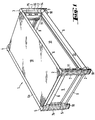
- Fig. 1
- eine erste Ausführungsform eines Gehäuses in perspektivischer Ansicht,
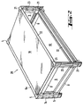
- Fig. 2
- eine zweite Ausführungsform eines Gehäuses in perspektivischer Ansicht,
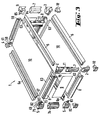
- Fig. 3
- das Gehäuse gemäß Fig. 1 in Explosivdarstellung,
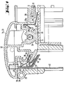
- Fig. 4
- einen Teil eines Gehäuses im Bereich einer Ecke im Querschnitt,
- Fig. 5
- einen Teil eines Gehäuses im Bereich der oberen Seite im Längsschnitt,
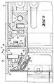
- Fig. 6
- einen Teil des Gehäuses im Bereich der unteren Ecke perspektivisch, teilweise in Explosivdarstellung und
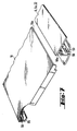
- Fig. 7
- eine Detaildarstellung eines Abdeckbleches mit Profilträger, im Ausschnitt.
- Fig. 1
- 1 shows a first embodiment of a housing in a perspective view,
- Fig. 2
- a second embodiment of a housing in a perspective view,
- Fig. 3
- 1 in an exploded view,
- Fig. 4
- a part of a housing in the area of a corner in cross section,
- Fig. 5
- a part of a housing in the area of the upper side in longitudinal section,
- Fig. 6
- a part of the housing in the area of the lower corner in perspective, partly in an exploded view and
- Fig. 7
- a detailed view of a cover plate with profile carrier, in the cutout.
Ein Tischgehäuse 1 einer ersten Ausführungsform weist Rahmen aus gleichen metallischen
Eckkörpern auf, von denen in Fig. 1 die oberen Eckkörper 2, 3, 4 und 5 bezeichnet sind. Die
entsprechenden unteren sichtbaren Eckkörper weisen wesentliche Bezugszeichen 2, 3 und 5
auf.A table housing 1 of a first embodiment has frames made of the same metallic
Corner bodies, of which the
Zwischen den Eckkörpern 2, 3, 4, 5 verlaufen vordere metallische Profilträger 6 in Breitenrichtung
des Gehäuses, hintere Profilträger 6 a in Breitenrichtung des Gehäuses, vordere bzw.
hintere Profilträger 7, 7 a in Höhenrichtung und Profilträger 8 in Tiefenrichtung des Gehäuses
1.Front metallic profile supports 6 run in the width direction between the
Die Eckkörper 2 bis 5 und Profilträger 6 bis 8 bilden jeweils die Rahmen des Gehäuses 1.The
Seitlich am Gehäuse 1 sind gleiche Seitenwände 9 vorgesehen, deren Ränder in Nuten der
Rahmen form- und kraftschlüssig eingesetzt sind. Die rückwärtige Gehäuseseite ist mit einer
in Fig. 1 nicht dargestellten Abdeckung verschlossen. Die obere und untere Seite des
Gehäuses 1 weist gleiche Abdeckungen 10 auf.The
In die offene Frontseite des Gehäuses 1 wird ein Baugruppenträger eingesetzt, der nicht
dargestellt ist. Zur Halterung des Baugruppenträgers sind beiderseits neben der Öffnung, d.h.
an den Eckkörpern 2,3 und den Profilträgern 7, Anschlagwinkel 11 angeschraubt. Die Profilträger
6 haben jeweils eine zur Außenseite des Gehäuses hin konvex gewölbte Fläche, die
sich beiderseits den Enden in entsprechenden Flächen der Eckkörper 3 bis hin zu einer
vertikalen Fläche 14 der Eckkörper 2, 3 fortsetzt. Die Profilträger 7 weisen jeweils eine
horizontale Fläche 15 auf, die in der Ebene der Breitenrichtung des Gehäuses 1 liegt. Die
Flächen 15, die sich in entsprechenden, nicht näher bezeichneten Flächen der Eckverbinder
fortsetzen, bilden seitliche Begrenzungen der in das Gehäuse 1 einsetzbaren Baugruppenträger.In the open front of the housing 1, a rack is used, which is not
is shown. To hold the subrack on both sides next to the opening, i.e.
screwed to the
Von den in bezug auf das Gehäuse 1 äußeren Rändern 16 der Flächen 15 und der an diese
angrenzenden, auf der gleichen vertikalen Ebene angeordneten Flächen der Eckkörper 3
gehen ebene Flächen 17 aus, die in der Ebene der Tiefenrichtung des Gehäuses liegen und
von den Flächen 15 aus rechtwinklig nach vorne vorspringen.Of the outer edges 16 with respect to the housing 1 of the
Die Flächen 17 setzen sich oben und unten in entsprechenden Flächen der Eckkörper 3 fort,
die nicht näher bezeichnet sind.The surfaces 17 continue at the top and bottom in corresponding surfaces of the
Die rechtwinklig zueinander verlaufenden Flächen 15, 17 mit den nach oben und unten
angrenzenden Flächen der Eckkörper 3 sind Anschlagflächen für Scharniere von Türen zur
Abdeckung der Frontseite des Gehäuses 1. Die Scharniere können wahlweise links oder
rechts angeschlagen werden.The
An der Unterseite der unteren Eckkörper 2, 3, 4 und 5 werden Beine 18 befestigt wie
angeschraubt, die auf ihrer Vorderseite nicht näher bezeichnete Flächen aufweisen, die je mit
den Flächen 15, 17 in einer Ebene liegen.On the underside of the
Fig. 2 zeigt ein Gehäuse 20, dessen Aufbau im Prinzip demjenigen des Gehäuses 1 entspricht,
d.h. es werden Rahmen aus gleichen vorderen Eckkörpern 21 und zwischen diesen
verlaufenden gleichen Profilträgern 22 in Breitenrichtung und gleichen Profilträgern 8 in
Tiefenrichtung gebildet.2 shows a
Zwischen den von den Eckkörpern 4, 5, 21 und den sich zwischen diesen erstreckenden
Profilträgern 7 a, 8, 23 gebildeten seitlichen Rahmen sind die Seitenwände 9 und zwischen
den oberen und unteren von den Eckkörpern 4, 5, 21 und den zwischen diesen verlaufenden
Profilträgern 6 a, 8, 22 gebildeten Rahmen die Abdeckungen 10 in Form der Abdeckplatten
angeordnet.Between those of the
Die Eckkörper 21 und Profilträger 23, 22 des vorderen Rahmens unterscheiden sich von den
Eckkörpern 2, 3 und den Profilträgern 7 durch Profile mit Nuten, in die Federn einlegbar
sind. The
Die rückwärtige Seite des Gehäuses 20 hat den gleichen Aufbau wie das Gehäuse 1, d.h. es
sind Eckkörper 4, 5 und vertikale Profilträger 7 a sowie horizontale Profilträger 6 a vorhanden.The rear side of the
Fig. 3 zeigt das Gehäuse 1 in Explosivdarstellung. Die vertikalen Profilträger 7 a haben den
in Fig. 4 näher dargestellten Querschnitt. Bei dem Gehäuse 20 sind die vorderen vertikalen
Profilträger 23 und die hinteren vertikalen Profilträger 7 a im Aufbau identisch. Die Profilträger
23 und 7 a haben einen Abschnitt 24 mit einer Durchbrechung wie Loch 25, in das
eine Schneidschraube von einem der Eckkörper 2, 3, 4, 5 aus eingeschraubt wird, um die
Profilträger 7 a, 23 mit jeweiligen Eckkörpern 4, 5 bzw. 2, 3 zu befestigen. Im Eckkörper 2,
3, 4, 5, 21 ist für die Schraube ein Loch vorgesehen, das in Fig. 3 und 4 nicht dargestellt ist.Fig. 3 shows the housing 1 in an exploded view. The
Der Abschnitt 24 hat eine breite Anschlagfläche 26 für die Anschlagwinkel 11. Neben der
Anschlagfläche 26 ist eine Nut 27 vorgesehen, in die eine Blattfeder 28 eingelegt ist, die mit
ihrem in der Nut 27 liegenden Teil gegen die Nutwände und mit einem aus der Nut 27
herausragenden Teil 29 gegen den Winkel 11 gedrückt wird und so eine leitende Verbindung
zwischen dem Profilträger 7 a bzw. 23 und dem Winkel 11 herstellt.The
Wie sich aus der Fig. 4 ergibt, ist die Blattfeder 28 unverlierbar in der Nut 27 angeordnet.
Hierzu weist die Blattfeder 28 einen sich entlang einer Begrenzungswandung der Nut 27
verlaufenden Schenkel 29 auf, von dem ein Abschnitt oder eine Fahne 29 b, die z.B. durch
eine Ausstanzung gebildet sein kann, zur gegenüberliegenden Wandung der Nut 27 abragt
und mit ihrem äußeren Ende an einem Vorsprung 27 a anlegbar ist, der parallel zum Boden
der Nut 27 verläuft. Hierdurch ist sichergestellt, dass die Blattfeder 28 nicht unkontrolliert
aus der Nut 27 herausrutschen kann.As can be seen from FIG. 4, the
Neben der Nut 27 verläuft ein Abschnitt 30 des Profilträgers 7 a bzw. 23, der eine in
Längsrichtung der Nut 27 betrachtet senkrecht hierzu verlaufende Nut 31 aufweist, die in
Längs- bzw. Tiefenrichtung des Profilträgers 7 a, 23 offen ist. In die Nut 31 ist die Seitenwand
9 mit ihrem Rand eingespannt. Der Profilträger 7 a bzw. 23 hat eine konvex nach
außen gewölbte Wand 32 und eine ebene Fläche 33, die in vertikaler Richtung verläuft und
der gleichen Fläche am gegenüberliegenden Profilträger des Rahmens zugewandt ist.In addition to the groove 27, a
Rechtwinklig zur Fläche 33 verläuft eine vertikale ebene Fläche 34, die beim Profilträger 7
a die Rückseite bildet. Beim Profilträger 23 ist die Fläche 34 die Vorderseite. In der Wand
mit der Fläche 34 ist eine schmale Nut 35 angeordnet, die unter einem Winkel zur Fläche 35
geneigt ist.At right angles to the
In der Nut 35 wird eine Blattfeder 36 eingelegt, deren eines Ende als Fahne 37 aus der Nut
35 herausragt.In the groove 35 a
Der Profilträger 23 kann mit einem Beschlag 38 bestückt werden, der ein Scharnier 39 hat.
Der Beschlag 38 wird an der Fläche 33 angeschraubt und trägt eine Tür 40, die an ihrem der
Fläche 33 zugewandten Rand derart angebördelt ist, dass eine parallel zu der Frontseite
verlaufende Zone 41 und eine schräg zur Frontseite verlaufende Randzone 42 vorhanden ist.
Gegen die Zone 41 ist bei geschlossener Tür 40 die Fahne 37 angedrückt, wodurch eine
Verbindung zwischen der Tür 40, die aus Metall, z.B. Aluminium oder metallisiertem
Material besteht und dem Profilträger 23 hergestellt wird.The
Die Randzone 42 hat in Schließstellung der Tür 40 einen geringen Abstand zu einer an die
Nut 35 angrenzenden Fläche 43 des Profilträgers 23. An der Randzone 42 ist eine Gummidichtung
44 oder elastische Kunststoffdichtung z.B. durch Kleben befestigt. Diese Dichtung
wird bei geschlossener Tür 40 gegen die Fläche 43 gedrückt, so dass der Spalt zwischen Tür
40 und Profilträger 23 gut abgedichtet wird.The
Die sich über die Breite des Gehäuses 1, 20 erstreckenden Profilträger 6, 6 a haben jeweils
einen Abschnitt 46 mit einem einer Ausnehmung wie Loch 47, in das eine Schneidschraube
48 eingesetzt wird, die den jeweiligen Eckkörper 2, 3, 4, 5, 21 mit dem Profilträger 6, 6 a
verbindet. Der Eckkörper 4 bzw. 5 bzw. 21 hat einen Vorsprung 49 mit einem Loch 50, in
das die Schneidschraube 48 eingesetzt wird. Der Profilträger 6 bzw. 6 a ist an seinen Seiten,
die die vordere bzw. rückseitige Gehäuseöffnung umgeben, gleich ausgebildet wie die
Profilträger 7 a und 23.The profile beams 6, 6a extending across the width of the
Es sind am Profilträger 6 a ebene Flächen 51, die horizontal verlaufen, und ebene Flächen
52, die rechtwinklig zu den Flächen 51 vertikal verlaufen, vorhanden. In den Flächen 52
befinden sich schräg zu den Flächen 52 verlaufende Nuten 53, in die Blattfedern 54 a
eingelegt sind, deren Enden als Fahnen 55 a aus den Nuten 53 herausragen. Die Zone 41 der
Tür 40 verläuft entlang aller vier Kanten der Tür 40. Auch die Randzone 42 ist an allen
Seiten der Tür 40 vorhanden. Die Dichtung 44 ist längs der gesamten Randzone 42 auf dieser
befestigt.There are 6
Neben der Nut 53 hat das Profil des Profilträgers 6 bzw. 22 die gleiche Form wie dasjenige
der Profilträger 7 a, 23, d.h. es ist eine schräg zur Fläche 52 verlaufende Fläche 43 vorhanden,
gegen die die Dichtung 44 bei geschlossener Tür 40 angedrückt wird, so dass die
frontseitige Öffnung des Gehäuses 20 vollständig abgedichtet wird.In addition to the
Die Profilträger 6 a, 22 haben jeweils eine in Abhängigkeit von der oberen und unteren
Anordnung im Rahmen oben oder unten verlaufende ebene Fläche 54 auf der Außenseite
einer Wand 55, die an einer Kante 56 endet, von der aus eine Wand 57 rechtwinklig zur
Wand 55 gegen die Mittelebene des Gehäuses 20 hin verläuft. Die Wand 57 geht in eine
Wand 58 auf der dem Inneren des Gehäuses 20 zugewandten Seite der Profilträger 6 a, 22
über. Die Wand 58 erstreckt sich bis zum Abschnitt 46, der in einer gewissen Entfernung von
der Wand 57 angeordnet ist und sich auf einem Niveau erstreckt, das nicht ganz die Höhe der
Wand 57 erreicht.The
Im Raum zwischen der Wand 57 und dem Abschnitt 46 springt eine Leiste 59 von der Wand
58 in Richtung der Außenseite des Gehäuses 20 vor. Das Ende 60 der Leiste 59 ist gegen der
Ebene der Fläche 54 zum Inneren in das Gehäuse 20 zurückversetzt. Die Leiste 59 teilt den
Raum zwischen der Wand 57 und dem Abschitt 46 in zwei Nuten 61, 62 auf. In the space between the
Die Abdeckungen 10 haben an den sich in die Tiefe des Gehäuses 1, 20 ersteckenden Seiten
um 90 ° abgewinkelte Ränder 63. An der Rück- und Vorderseite sind die Abdeckungen 10
jeweils mit einem Rand 64 versehen, der gegen die obere bzw. untere Seite der Abdeckung
10 um 90 ° abgewinkelt ist. Zusätzlich geht der Rand 64 in eine um 90 ° abgewinkelte
Endzone 65 über. Die abgewinkelten Ränder geben der Abdeckung 10 eine große Stabilität,
so dass die Abdeckungen 10 dünnwandig ausgebildet sein können.The
Der Rand 64 der Abdeckung 10 wird in die Nut 61 eingesetzt, wobei die Endzone 65 an der
Wand 58 anliegt. Der Rand 64 ist höher als die Leiste 59. Zwischen dem Ende 60 und der
Abdeckung 10 ist eine Dichtung 66 eingespannt. In die Nut 62 ist eine Blattfeder 67 eingelegt,
deren Ende über die Nut 62 hinausragt und gegen die Abeckung 10 gedrückt ist, um
eine elektrisch leitende Verbindung zwischen der Abdeckung 10 und dem Profilträger 6 a
bzw. 22 herzustellen. Die Blattfeder 67 ist dabei unverlierbar in der Nut 62 angeordnet.The
Die Blattfedern 36, 28, 54 und 67 sind nicht erforderlich, wenn keine besondere Abschirmung
des Inneren des Gehäuses 20 gegen elektromagnetische Störfelder gewünscht wird.
Ebenso sind die Dichtungen 44 und 66 nicht notwendig, wenn geringere Anforderungen an
den Schutz der Komponenten im Gehäuseinneren erfüllt werden müssen.The leaf springs 36, 28, 54 and 67 are not required if no special shielding
the interior of the
Die Profilträger 8 haben jeweils zwei, dem Gehäuseinneren zugewandte Längsnuten 68, 69
eine Längsnut 70, in die jeweils der Rand einer Wand 9 eingesetzt ist, und einen Absatz mit
zwei rechtwinklig zueinander verlaufenden Längswänden 71, 72. Der Absatz befindet sich auf
der der Gehäuseaußenseite zugewandten Profilseite. Von der Längswand 71 springt eine
Leiste 73 parallel zur Längswand 72 vor, hat jedoch nicht die Höhe der Längswand 72.The profile supports 8 each have two
Die Längswand 71 geht nach der Gehäuseaußenseite in einen weiteren, schmalen Absatz 74
über. Die abgewinkelten Ränder 63 der Abdeckung 10 stützen sich auf den Absätzen 74 der
Profilträger 8 ab. In die Nuten zwischen den Seitenwänden 72 und den Leisten 73 können
Blattfedern eingelegt sein, deren aus den Nuten herausragende Fahnen an der Abdeckung
anliegen und so eine elektrisch leitende Verbindung zwischen den Profilschienen 8 und den
Abdeckungen 10 herstellen. Zwischen den Spitzen der Leisten 73 und den Abdeckungen 10
können Dichtungen eingespannt sein.The
Die Eckkörper 2, 3, 4, 5 und 21 haben eine nach oben bzw. unten offene Nut 75, die
rechtwinklig ihren Verlauf ändert. Auf der einen Seite der Nut 75 befindet sich der Block
bzw. Vorsprung 49 mit dem Loch 50. Im Eckkörper 2, 3, 4, 5 und 21 ist weiterhin ein Loch
77 im Nutboden vorgesehen, in das eine Schneidschraube 78 eingesetzt wird, mit der die
Profilträger 7 bzw. 7 a am jeweiligen Eckverbinder befestigt werden.The
Von den Innenseiten der Ränder 64 gehen zylinder- oder kegelstumpfförmige Vorsprünge 79
mit Innengewinden aus. Die Eckkörper 2, 3, 4, 5, 21 haben jeweils Löcher 80, in die
Schrauben 81 eingesetzt werden, mit denen die Ränder 64 bzw. die Abdeckungen an den
Eckkörpern angeschraubt werden.Cylindrical or
Von den Eckkörpern 2, 4, 5, 21 gehen weiterhin Nasen 82, 83 aus, die in die Nuten 68, 69
der Profilträger 8 ragen und eine formschlüssige Verbindung zu diesen herstellen.
In den Nasen 82, 83 sind jeweils Löcher 84, 85 vorhanden, in die Schneidschrauben eingesetzt
werden, mit denen jeweils die Profilträger 8 an den Eckkörpern 2, 4, 5, 21 und die
Winkel 11 an den Eckkörpern 2, 4, 5, 21 befestigt werden.
Durch die schmale Ausbildung der Nuten 35 und 53 und deren geneigten bzw. schrägen
Verlauf zu den Wandungen bzw. Flächen 34, 52, von denen erstere ausgehen; tritt bei der
Beschichtung der Gehäuseteile kein Lack in die Nuten 35, 53 ein. Beim Lackieren müssen
die Nuten 35, 53 daher nicht eigens abgedeckt werden, wodurch sich Einsparungen bei der
Herstellung der Teile ergeben.Due to the narrow design of the
In Fig. 7 ist im Ausschnitt ein Abdeckblech 10 dargestellt, dessen einer Rand U-förmig
gekantet ist, wie dies auch in Fig. 5 dargestellt wird. Der Rand weist folglich zur Außenfläche
des Abdeckbleches 10 um rechte Winkel abgekantete Schenkel 64 und 65 auf. In Fig. 7, a
Gegenüberliegend ist das Abdeckblech 10 nicht umgebogen und wird in einem Profilträger
6, 6 a oder 22 eingesetzt, und zwar in eine Nut 58 a. Ansonsten weist der Profilträger 6, 6
a bzw. 22 einen prinzipiellen Aufbau auf, wie dieser anhand der Fig. 5 erläutert worden ist.Opposite the
Dadurch, dass das Abdeckblech 10 in die Nut 58 a mit seinem vorderen Rand 10 a eingesteckt
ist, um eine Festlegung und Befestigung sicherzustellen, ist der Vorteil gegeben, dass
Abdeckbleche 10 auf eine gewünschte Tiefe abgelenkt werden können, wodurch sich sowohl
bei der Herstellung als auch Bevorratung von vorgefertigten Abdeckblechen 10 Vorteile
ergeben.Characterized in that the
Claims (9)
dadurch gekennzeichnet,
dass die Gehäusekanten metallische Profilträger (6, 6 a, 7, 7 a, 8, 22, 23) und die Gehäuseecken metallische Eckkörper (2, 3, 4, 5, 21) sind, dass jeder Eckkörper mit drei Profilträgern verschraubt ist, die sich in drei jeweils rechtwinklig zueinander ausgerichteten Richtungen erstrecken, dass die Seitenwände (9) durch in Nuten (31) zumindest der vorderen und rückwärtigen Profilträger (7, 7 a, 23) eingespannte Platten (9) gebildet sind und dass die oberen und unteren Wände (10) als mit ihren Rändern in Nuten (61) der vorderen und rückwärtigen Profilträger (6, 6 a, 22) und Absätze (74) der seitlichen Profilträger (8) eingesetzte metallische Platten ausgebildet sind. Housing made of metal or metallized material for electrical assemblies and components with housing edges (6, 6 a, 7, 7 a, 8, 22, 23) and housing corners (2, 3, 4, 5, 21) comprising frames and side walls that can be received by them (9) and upper and lower walls (10),
characterized by
that the housing edges are metallic profile carriers (6, 6 a, 7, 7 a, 8, 22, 23) and the housing corners are metallic corner bodies (2, 3, 4, 5, 21), that each corner body is screwed to three profile carriers, which extend in three directions, each at right angles to one another, that the side walls (9) are formed by plates (9) clamped in grooves (31) at least of the front and rear profile supports (7, 7 a, 23) and that the upper and lower walls (10) as with their edges in grooves (61) of the front and rear profile beams (6, 6 a, 22) and shoulders (74) of the side profile beams (8) inserted metallic plates are formed.
dadurch gekennzeichnet,
dass die Profilträger (6, 6 a, 22, 7, 7 a, 23) jeweils eine in ihrer Achsrichtung verlaufende Ausnehmung wie Loch (25, 47) aufweisen, das mit einer Ausnehmung wie Loch (77, 50) in dem formschlüssig an den Profilträger (6, 6 a, 23, 7, 7 a, 23) anlegbaren Eckkörper (2, 3, 4, 5, 21) fluchtet und in das ein Verbindungselement wie Schneidschraube (48, 78) einsetzbar ist, mit der der jeweilige Profilkörper am Eckkörper befestigbar ist.Housing according to claim 1,
characterized by
that the profile carriers (6, 6 a, 22, 7, 7 a, 23) each have a recess in their axial direction, such as a hole (25, 47), which has a recess in the form of a hole (77, 50) in the Profile carrier (6, 6 a, 23, 7, 7 a, 23) alignable corner body (2, 3, 4, 5, 21) is aligned and into which a connecting element such as tapping screw (48, 78) can be used, with which the respective profile body can be attached to the corner body.
dadurch gekennzeichnet,
dass für die Frontseite zwei verschiedene Arten von Profilträgern (6, 22) und Eckkörpern (2, 3, 21) vorgesehen sind.Housing according to claim 1 or 2,
characterized by
that two different types of profile beams (6, 22) and corner bodies (2, 3, 21) are provided for the front.
dadurch gekennzeichnet,
dass bei der einen Art von Profilträgern (6, 7) und Eckkörpern (2, 3) zur Frontseite hin nutenlose, glatte Flächen (13, 15, 17) vorgesehen sind.Housing according to claim 3,
characterized by
that with one type of profile beams (6, 7) and corner bodies (2, 3) groove-free, smooth surfaces (13, 15, 17) are provided towards the front.
dadurch gekennzeichnet,
dass in den Profilträgern (22, 23) und Eckkörper (21), die das Gehäuse vorder- und rückseitig rahmenartig umgeben, an ihrer Vorder- und Rückseite jeweils eine offene, schmale Nut (35, 53) für Blattfedern (36, 54) bzw. elektrisch leitenden Verbindungen zu Front- und Abdeckplatten aufweisen.Housing according to claim 3,
characterized by
that in the profile beams (22, 23) and corner body (21), which surround the housing front and back like a frame, each have an open, narrow groove (35, 53) for leaf springs (36, 54) and have electrically conductive connections to the front and cover plates.
dadurch gekennzeichnet,
dass horizontal verlaufende Profilträger (6, 6 a, 22) und beiderseits mit diesen verbundene Eckkörper (2, 3, 21) nach oben bzw. unten offene, parallele Nuten (61, 62) aufweisen, von denen die näher an den Gehäusemitten angeordneten Nuten (62) mit Anschlagfläche für Blattfedern (67) versehen sind, die mit Endabschnitten unverlierbar in den Nuten gehalten sind und mit Fahnen aus den Nuten als Anschlagflächen an Abdeckungen (10) anliegend herausragen.Housing according to at least one of the preceding claims,
characterized by
that horizontally extending profile beams (6, 6 a, 22) and on both sides connected to them corner bodies (2, 3, 21) have parallel grooves (61, 62) open at the top and bottom, of which the grooves arranged closer to the center of the housing (62) are provided with an abutment surface for leaf springs (67), which are held captive in the grooves with end sections and protrude from the grooves with abutments as abutment surfaces against covers (10).
dadurch gekennzeichnet,
dass die obere und untere Abdeckung (10) aus metallischen ebenen Blechen mit an drei Seiten rechtwinklig abgewinkelten Rändern (63, 64) besteht, von denen an einer Seite der Rand zusätzlich eine rechtwinklig abgewinkelte Randzone (65) aufweist.Housing according to at least one of the preceding claims,
characterized by
that the upper and lower cover (10) consists of flat metal sheets with edges (63, 64) angled at right angles on three sides, of which the edge additionally has a right angled edge zone (65) on one side.
dadurch gekennzeichnet,
dass an den Eckkörpern (2, 3, 4, 5, 21) in Richtung der Seitenwände Laschen (82) vorgesehen sind, die in Nuten (69) der die Seitenwände (9) oben und unten begrenzenden Profilträger (8) eingreifen und wenigstens eine Gewindebohrung zum Anschrauben von Winkeln (11) für die Befestigung mit seitlichen Rändern von Baugruppenträgern aufweisen.Housing according to at least one of the preceding claims,
characterized by
that tabs (82) are provided on the corner bodies (2, 3, 4, 5, 21) in the direction of the side walls, which engage in grooves (69) of the profile supports (8) delimiting the top and bottom of the side walls (9) and at least one Have a threaded hole for screwing on brackets (11) for fastening with side edges of subracks.
dadurch gekennzeichnet,
dass die Abdeckplatte (10) entlang eines Längsrandes U-förmig abgekantet und auf gegenüberliegender Seite ungekantet in einer Nut (58 a) eines Profilträgers (6, 6 a, 22) einsteckbar ist.Housing according to at least one of the preceding claims,
characterized by
that the cover plate (10) is bent in a U-shaped manner along a longitudinal edge and can be inserted on the opposite side without being folded into a groove (58 a) of a profile carrier (6, 6 a, 22).
Applications Claiming Priority (2)
| Application Number | Priority Date | Filing Date | Title |
|---|---|---|---|
| DE1996146481 DE19646481C2 (en) | 1996-11-11 | 1996-11-11 | Housings for electrical components and assemblies |
| DE19646481 | 1996-11-11 |
Publications (2)
| Publication Number | Publication Date |
|---|---|
| EP0841841A2 true EP0841841A2 (en) | 1998-05-13 |
| EP0841841A3 EP0841841A3 (en) | 1999-06-30 |
Family
ID=7811271
Family Applications (1)
| Application Number | Title | Priority Date | Filing Date |
|---|---|---|---|
| EP97119677A Withdrawn EP0841841A3 (en) | 1996-11-11 | 1997-11-11 | Enclosure for electrical components and assemblies |
Country Status (2)
| Country | Link |
|---|---|
| EP (1) | EP0841841A3 (en) |
| DE (1) | DE19646481C2 (en) |
Cited By (4)
| Publication number | Priority date | Publication date | Assignee | Title |
|---|---|---|---|---|
| DE19814997A1 (en) * | 1998-04-03 | 1999-10-14 | Bopla Gehaeuse Systeme Gmbh | Block-shaped casing with at least two parts for integration of electric or electronic components |
| WO1999065283A1 (en) * | 1998-06-09 | 1999-12-16 | Hybricon Corporation | Modular card cage with continuous emi shielding |
| EP1001670A2 (en) * | 1998-11-09 | 2000-05-17 | VERO Electronics GmbH | Electronic rack |
| EP1437929A2 (en) * | 2003-01-09 | 2004-07-14 | Palima W. Ludwig & Co. | Housing made of aluminium profiles for electrical and electronic components |
Families Citing this family (3)
| Publication number | Priority date | Publication date | Assignee | Title |
|---|---|---|---|---|
| DE20200720U1 (en) | 2002-01-18 | 2002-05-29 | Harting Electric Gmbh & Co Kg | Modular control housing |
| DE202011100118U1 (en) * | 2011-05-03 | 2011-06-27 | Kubik, Ralf, 63849 | Size-adjustable diving bell |
| DE202019103617U1 (en) | 2019-07-01 | 2019-08-01 | Kws Computersysteme Gmbh | Housing, in particular for electronic components |
Citations (5)
| Publication number | Priority date | Publication date | Assignee | Title |
|---|---|---|---|---|
| US4078847A (en) * | 1976-05-11 | 1978-03-14 | Presnick Michael C | Electronic equipment enclosure |
| FR2371856A1 (en) * | 1976-11-18 | 1978-06-16 | Tektronix Inc | MODULAR CABINETS FOR ELECTRONIC DEVICES |
| DE2920320A1 (en) * | 1979-05-19 | 1980-11-20 | Horn Hans Joachim | Housing comprising case with frame - has corner pieces and four front profiles held together by screws that fix front plate |
| DE8107658U1 (en) * | 1981-03-17 | 1981-08-20 | Hans Knürr KG Mechanik für die Elektronik, 8000 München | Housings, in particular for electrical and / or electronic circuits |
| DE9209519U1 (en) * | 1992-07-16 | 1992-08-27 | Schroff Gmbh, 7541 Straubenhardt, De |
Family Cites Families (1)
| Publication number | Priority date | Publication date | Assignee | Title |
|---|---|---|---|---|
| DE3608984A1 (en) * | 1985-04-12 | 1986-10-23 | G.D S.P.A., Bologna | DUST-PROOF CABINET, ESPECIALLY FOR ELECTRICAL SYSTEMS |
-
1996
- 1996-11-11 DE DE1996146481 patent/DE19646481C2/en not_active Expired - Fee Related
-
1997
- 1997-11-11 EP EP97119677A patent/EP0841841A3/en not_active Withdrawn
Patent Citations (5)
| Publication number | Priority date | Publication date | Assignee | Title |
|---|---|---|---|---|
| US4078847A (en) * | 1976-05-11 | 1978-03-14 | Presnick Michael C | Electronic equipment enclosure |
| FR2371856A1 (en) * | 1976-11-18 | 1978-06-16 | Tektronix Inc | MODULAR CABINETS FOR ELECTRONIC DEVICES |
| DE2920320A1 (en) * | 1979-05-19 | 1980-11-20 | Horn Hans Joachim | Housing comprising case with frame - has corner pieces and four front profiles held together by screws that fix front plate |
| DE8107658U1 (en) * | 1981-03-17 | 1981-08-20 | Hans Knürr KG Mechanik für die Elektronik, 8000 München | Housings, in particular for electrical and / or electronic circuits |
| DE9209519U1 (en) * | 1992-07-16 | 1992-08-27 | Schroff Gmbh, 7541 Straubenhardt, De |
Cited By (8)
| Publication number | Priority date | Publication date | Assignee | Title |
|---|---|---|---|---|
| DE19814997A1 (en) * | 1998-04-03 | 1999-10-14 | Bopla Gehaeuse Systeme Gmbh | Block-shaped casing with at least two parts for integration of electric or electronic components |
| DE19814997C2 (en) * | 1998-04-03 | 2002-01-03 | Bopla Gehaeuse Systeme Gmbh | Cuboid housing for the installation of components |
| WO1999065283A1 (en) * | 1998-06-09 | 1999-12-16 | Hybricon Corporation | Modular card cage with continuous emi shielding |
| US6349041B1 (en) | 1998-06-09 | 2002-02-19 | Hybricon Corporation | Modular card cage with continuous EMI shielding |
| EP1001670A2 (en) * | 1998-11-09 | 2000-05-17 | VERO Electronics GmbH | Electronic rack |
| EP1001670A3 (en) * | 1998-11-09 | 2000-12-06 | APW Electronics GmbH | Electronic rack |
| EP1437929A2 (en) * | 2003-01-09 | 2004-07-14 | Palima W. Ludwig & Co. | Housing made of aluminium profiles for electrical and electronic components |
| EP1437929A3 (en) * | 2003-01-09 | 2005-08-17 | Palima W. Ludwig & Co. | Housing made of aluminium profiles for electrical and electronic components |
Also Published As
| Publication number | Publication date |
|---|---|
| DE19646481C2 (en) | 2000-04-06 |
| EP0841841A3 (en) | 1999-06-30 |
| DE19646481A1 (en) | 1998-05-14 |
Similar Documents
| Publication | Publication Date | Title |
|---|---|---|
| EP0686316B1 (en) | Cabinet | |
| EP0939984B1 (en) | Switching cabinet | |
| EP0528240B1 (en) | Equipment cabinet | |
| EP1002351A1 (en) | Rack with several assembly levels | |
| EP0650317B1 (en) | Electronic rack | |
| DE3928461C3 (en) | Subrack | |
| DE19646481C2 (en) | Housings for electrical components and assemblies | |
| DE4114484C2 (en) | Subrack | |
| DE3144131C2 (en) | ||
| DE19811711C1 (en) | Wall-mounted installation housing | |
| DE19801720C1 (en) | Connector plate and fixing bracket for panels of switchgear enclosure | |
| DE4109695C1 (en) | ||
| EP0010291B1 (en) | Switch cabinet | |
| EP0516986B1 (en) | Electronic rack | |
| EP3270666B1 (en) | Device for receiving electronic components | |
| DE4237447A1 (en) | Subrack | |
| DE102007052943B4 (en) | In a mounting wall permanently installed control and / or communication device | |
| WO1998023011A1 (en) | Assembly unit with an assembly rail | |
| EP0937374B1 (en) | Sub-rack with at least one front-sided vertical assembly groove | |
| DE19835380C1 (en) | Switch cabinet for electrical or electronic switch modules; has vertical fixing edges for switch modules positioned between front and rear parts of cabinet side walls | |
| DE3440008A1 (en) | PACKED BUSBAR | |
| DE19835379C1 (en) | Switch cabinet for electrical or electronic switch modules; has casing body assembled from two steel sheet metal frames with vertical fixing plane for switch modules between them | |
| DE19851589C2 (en) | Subrack | |
| DE10208401C1 (en) | Component set for screened multi-switch housing has rectangular frame fitted between base and cover provided with solder pins locating in holes around peripheral edge of enclosed circuit board | |
| DE102007052942B4 (en) | Electric function module |
Legal Events
| Date | Code | Title | Description |
|---|---|---|---|
| PUAI | Public reference made under article 153(3) epc to a published international application that has entered the european phase |
Free format text: ORIGINAL CODE: 0009012 |
|
| AK | Designated contracting states |
Kind code of ref document: A2 Designated state(s): AT BE CH DE DK ES FI FR GB GR IE IT LI LU MC NL PT SE |
|
| AX | Request for extension of the european patent |
Free format text: AL;LT;LV;RO;SI |
|
| PUAL | Search report despatched |
Free format text: ORIGINAL CODE: 0009013 |
|
| AK | Designated contracting states |
Kind code of ref document: A3 Designated state(s): AT BE CH DE DK ES FI FR GB GR IE IT LI LU MC NL PT SE |
|
| AX | Request for extension of the european patent |
Free format text: AL;LT;LV;RO;SI |
|
| RIC1 | Information provided on ipc code assigned before grant |
Free format text: 6H 05K 7/14 A, 6H 05K 7/18 B, 6H 05K 5/04 B |
|
| AKX | Designation fees paid | ||
| STAA | Information on the status of an ep patent application or granted ep patent |
Free format text: STATUS: THE APPLICATION IS DEEMED TO BE WITHDRAWN |
|
| 18D | Application deemed to be withdrawn |
Effective date: 19991231 |
|
| REG | Reference to a national code |
Ref country code: DE Ref legal event code: 8566 |