EP0841690B1 - Tungsten nitride (WNx) layer manufacturing method and metal wiring manufacturing method - Google Patents
Tungsten nitride (WNx) layer manufacturing method and metal wiring manufacturing method Download PDFInfo
- Publication number
- EP0841690B1 EP0841690B1 EP96308176A EP96308176A EP0841690B1 EP 0841690 B1 EP0841690 B1 EP 0841690B1 EP 96308176 A EP96308176 A EP 96308176A EP 96308176 A EP96308176 A EP 96308176A EP 0841690 B1 EP0841690 B1 EP 0841690B1
- Authority
- EP
- European Patent Office
- Prior art keywords
- layer
- tungsten
- metal wiring
- manufacturing
- semiconductor device
- Prior art date
- Legal status (The legal status is an assumption and is not a legal conclusion. Google has not performed a legal analysis and makes no representation as to the accuracy of the status listed.)
- Expired - Lifetime
Links
Images


Classifications
-
- H—ELECTRICITY
- H01—ELECTRIC ELEMENTS
- H01L—SEMICONDUCTOR DEVICES NOT COVERED BY CLASS H10
- H01L21/00—Processes or apparatus adapted for the manufacture or treatment of semiconductor or solid state devices or of parts thereof
- H01L21/70—Manufacture or treatment of devices consisting of a plurality of solid state components formed in or on a common substrate or of parts thereof; Manufacture of integrated circuit devices or of parts thereof
- H01L21/71—Manufacture of specific parts of devices defined in group H01L21/70
- H01L21/768—Applying interconnections to be used for carrying current between separate components within a device comprising conductors and dielectrics
- H01L21/76838—Applying interconnections to be used for carrying current between separate components within a device comprising conductors and dielectrics characterised by the formation and the after-treatment of the conductors
- H01L21/76841—Barrier, adhesion or liner layers
- H01L21/76853—Barrier, adhesion or liner layers characterized by particular after-treatment steps
- H01L21/76855—After-treatment introducing at least one additional element into the layer
-
- H—ELECTRICITY
- H01—ELECTRIC ELEMENTS
- H01L—SEMICONDUCTOR DEVICES NOT COVERED BY CLASS H10
- H01L21/00—Processes or apparatus adapted for the manufacture or treatment of semiconductor or solid state devices or of parts thereof
- H01L21/70—Manufacture or treatment of devices consisting of a plurality of solid state components formed in or on a common substrate or of parts thereof; Manufacture of integrated circuit devices or of parts thereof
- H01L21/71—Manufacture of specific parts of devices defined in group H01L21/70
- H01L21/768—Applying interconnections to be used for carrying current between separate components within a device comprising conductors and dielectrics
- H01L21/76838—Applying interconnections to be used for carrying current between separate components within a device comprising conductors and dielectrics characterised by the formation and the after-treatment of the conductors
- H01L21/76841—Barrier, adhesion or liner layers
- H01L21/76843—Barrier, adhesion or liner layers formed in openings in a dielectric
-
- H—ELECTRICITY
- H01—ELECTRIC ELEMENTS
- H01L—SEMICONDUCTOR DEVICES NOT COVERED BY CLASS H10
- H01L21/00—Processes or apparatus adapted for the manufacture or treatment of semiconductor or solid state devices or of parts thereof
- H01L21/70—Manufacture or treatment of devices consisting of a plurality of solid state components formed in or on a common substrate or of parts thereof; Manufacture of integrated circuit devices or of parts thereof
- H01L21/71—Manufacture of specific parts of devices defined in group H01L21/70
- H01L21/768—Applying interconnections to be used for carrying current between separate components within a device comprising conductors and dielectrics
- H01L21/76838—Applying interconnections to be used for carrying current between separate components within a device comprising conductors and dielectrics characterised by the formation and the after-treatment of the conductors
- H01L21/76877—Filling of holes, grooves or trenches, e.g. vias, with conductive material
- H01L21/76879—Filling of holes, grooves or trenches, e.g. vias, with conductive material by selective deposition of conductive material in the vias, e.g. selective C.V.D. on semiconductor material, plating
Landscapes
- Engineering & Computer Science (AREA)
- Physics & Mathematics (AREA)
- Condensed Matter Physics & Semiconductors (AREA)
- General Physics & Mathematics (AREA)
- Manufacturing & Machinery (AREA)
- Computer Hardware Design (AREA)
- Microelectronics & Electronic Packaging (AREA)
- Power Engineering (AREA)
- Internal Circuitry In Semiconductor Integrated Circuit Devices (AREA)
Description
- The present invention relates to a method for manufacturing a semiconductor device. In particular aspects, it relates to a method for manufacturing a tungsten nitride (WNx) layer which is selectively formed in a contact hole.
- JP 03-220720 A describes a semiconductor device in which the diffusion of a base electrode (Au) to the wiring material (Al) is reduced by forming a tungsten nitride film when a collector hole is buried by selective deposition of a tungsten film by CVD.
- US-A-5487923 relates to a method for depositing tungsten nitride thin films prior to formation of tungsten thin films by plasma-enhanced CVD which uses WF6-H2 reactant gas, in which the tungsten nitride layer prevents corrosion of the silicon semiconductor substrate by the fluorine atoms during deposition of the tungsten layer.
- US-A-5429989 relates to a method of making a semiconductor device wherein, in one embodiment, a titanium silicide ohmic layer is formed on a semiconductor substrate exposed by a contact hole etched in an insulating layer; and a tungsten nitride diffusion barrier layer is subsequently deposited in the contact hole and a metal layer formed thereon.
- With an increase in the integration level of semiconductor integrated circuits (ICs), the width of a metal interconnection line is required to decrease and the aspect ratio of a contact hole is required to continue to increase. However, aluminum (Al) alloy films currently being used as materials for metal wiring show bad step coverage in a contact hole or cause voids due to their formation by sputtering. As a result, shorts occur between metal interconnection lines, thereby lowering the reliability of ICs. Therefore, selective chemical vapor deposition-tungsten (SCVD-W) has attracted much attention for the use of tungsten (W) as the material for metal wiring by CVD.
- FIGS. 1A through 1E illustrate a method for forming a tungsten layer by CVD.
- In FIG. 1A, an
impurity region 12 for defining a source/drain region is formed by implanting ions into asilicon substrate 10. Then, a silicon oxide layer is formed as aninsulating layer 13 to a thickness of 500-2000Å (10Å = 1nm) on the overall surface of thesubstrate 10 including theimpurity region 12. As shown in FIG. 1B, atrench 19 for forming a metal wiring therein is formed by etching theinsulating layer 13 and thesilicon substrate 10 to a predetermined depth. - Subsequently, a titanium (Ti) layer is deposited to a thickness of 200-1500Å, on the
insulating layer 13 and in thetrench 19, and thermally treated. As a result of the thermal treatment, thesilicon substrate 10 reacts with the Ti layer, thus forming a titanium silicide (TiSix)layer 14 acting as an ohmic layer only on the contact surface with the substrate. Then, the remaining Ti which did not react with the substrate is removed by wet etching, and the resultant shown in FIG. 1C is obtained. - Thereafter, as shown in FIG. 1D, a titanium nitride (TiN) layer is deposited as a diffusion-
barrier layer 15 to a thickness of 150-900Å and atungsten layer 16 is deposited on the diffusion-barrier layer 15 to a thickness of 1000Å or above. - Then, the resultant is etched back by chemical mechanical polishing (CMP) so that the
tungsten layer 16 remains only in thetrench 19 as shown in FIG. 1E, thus, completing the metal wiring. - As described above, however, when metal wiring is formed by SCVD-W, the TiN layer acting as a diffusion-barrier layer has physical properties, for example, tensile force, different from those of the W layer being a metal wiring layer, and the interface between the layers is highly stressed. Consequently, the tungsten layer is lifted, especially the TiN layer/W layer which may be lifted from the insulation layer during CMP, in which physical force is applied.
- On the other hand, when the impurity region is formed of boron (B), being a P+ impurity, the impurity reacts with Ti in a subsequent thermal process, thus forming TiB2. As a result, the ohmic contact characteristics are degraded, and contact resistance is increased.
- To overcome the above problem, a method as shown in FIG. 2A has been suggested in which a
tungsten layer 24 is formed as an ohmic layer and then atungsten nitride layer 25 is formed as a diffusion-barrier layer on animpurity area 22 formed on asilicon substrate 20 and then atungsten layer 26 is formed as a metal wiring layer. - In the above method, the
tungsten layer 24 being an ohmic layer is formed to a thickness of 200-1500Å by flowing tungsten fluoride (WF6) at 6sccm and hydrogen (H2) at 200sccm, respectively, at a deposition temperature of 600°C under a pressure of 0.1Torr (1Torr = 133Pa). Then, thetungsten nitride layer 25 being a diffusion-barrier layer is deposited to a thickness of 150-900Å, and thetungsten layer 26 is deposited to a thickness of 1000Å or above on thetungsten nitride layer 25. The resultant is etched back, thus completing a metal wiring. A section of the metal wiring is shown in a scanning electron microscopy (SEM) photo of FIG. 2B. - However, the tungsten layer formed as an ohmic layer shows excellent adhesion to silicon, whereas reduction reaction of tungsten with silicon for forming tungsten silicide leads to encroachment on a silicon substrate and thus deterioration in the electrical characteristics thereof, as shown in FIG. 2B. Encroachment is becoming a more serious problem in the ULSI era in which junction depth is decreased to 0.1µm or less. Furthermore, since tungsten reacts with Si at 550°C or above, it is difficult to apply the above metal wiring manufacturing method to manufacturing process of semiconductor device when a subsequent process must be performed at a temperature higher than 550°C.
- To overcome the above problems, the object of the present invention is to provide a method for manufacturing metal wiring for a semiconductor device.
- The invention provides a method of manufacturing a metal wiring for a semiconductor device, comprising the steps of:
- (a) forming an insulating layer on a semiconductor substrate having a conductive layer formed thereon;
- (b) forming a contact hole by etching said insulating layer to expose said conductive layer;
- (c) forming an ohmic layer by depositing tungsten silicide on the conductive layer exposed by said contact hole;
- (d) forming a diffusion-barrier layer by subsequently selectively depositing a tungsten nitride layer in situ on said ohmic layer and sidewalls of the contact hole by reacting a nitrogen-containing gas and a tungsten source gas by controlling flow rates of the gases such that the flow rate of the nitrogen-containing gas is from 2 to 7 times the flow rate of the tungsten source gas, so as to prevent formation of a tungsten nitride layer on the insulating layer outside the contact hole; and
- (e) depositing a metal layer on said diffusion-barrier layer.
- In a particular embodiment of the invention step (d) comprises reacting the gas mixture of the nitrogen-containing gas and the tungsten source gas with a reducing agent gas.
- In preferred embodiments of the present invention, it is preferable to use one of WF6 and WCl6 as the tungsten source gas, one of N2, NH3, and methyl hydrazine as the nitrogen-containing gas, and one of H2, SiH4, SiH1Cl3, SiH2Cl2, and PH3 as the reducing agent gas.
- The flow-rate ratio of the nitrogen-containing gas to the tungsten source gas is 2-7. The flow-rate ratio of the reducing agent gas to the tungsten source gas is 0-500, more preferably 20-50.
- Examples for aiding understanding the present invention are described in detail below, by way of example, with reference to the attached drawings, in which:
- FIGS. 1A through 1E are sectional views explaining a conventional method for manufacturing a metal wiring structure of Ti/TiN/W;
- FIG. 2A is a sectional view explaining a conventional method for manufacturing a metal wiring structure of W/WNx/W
- FIG. 2B is an SEM photo showing a section of the metal wiring shown in FIG. 2A;
- FIG. 3 is a sectional view of a process chamber for depositing a WNx layer;
- FIGS. 4A through 4D are SEM photos showing sections of a TiN layer which selectively grows according to the flow rate of NH3 gas;
- FIG. 5 is a graph showing X-ray diffraction results of the WN layer;
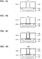
- FIGS. 6A through 6D are sectional views explaining a method for manufacturing a metal wiring of a semiconductor device;
- FIGS. 7A and 7B are sectional views explaining a method for manufacturing a metal wiring of a semiconductor device; and
- FIGS. 8A through 8E are sectional views of a method for manufacturing a metal wiring of a semiconductor device.
- FIG. 3 is a sectional view of a CVD process chamber for depositing a WNx layer.
- Referring to FIG. 3, a
susceptor 30 for loading a wafer thereon is installed in the lower part of aprocess chamber 40. AnIR lamp 39 is installed in the upper part to heat the temperature of awafer 32 to a temperature appropriate for reaction. A tungsten source gas and a nitrogen-containing gas are injected through afirst gas inlet 34 and flow horizontally across thewafer 32 loaded on thesusceptor 30. A reducing agent gas is injected through asecond gas inlet 36, flow vertically to thewafer 32 through amesh nozzle 38, and react with the gases introduced from thefirst gas inlet 34, thereby forming a WNx layer on thewafer 32. The gases are exhausted through anoutlet 42 opposing the first andsecond gas inlets - Contamination sources which might be produced in the
process chamber 40 are minimized by setting the process chamber at near vacuum of 10-6Torr or below. Then, thesusceptor 30 is loaded with a silicon substrate having an impurity region formed thereon or a silicon substrate including an underlying metal wiring layer which is formed of one of a pure metal such as aluminum (A1), tungsten (W), molybdenum (Mo), cobalt (Co), titanium (Ti), copper (Cu), and platinum (Pt), their silicide compound, and their alloy. Theprocess chamber 40 is heated to 200-700°C by theIR lamp 39, and then reactive gases are introduced through the first andsecond gas inlets first gas inlet 34. Preferably, one of H2, SiH4, SiH1Cl3, SiH2Cl2 , and PH3 is used as the reducing agent gas injected through thesecond gas inlet 36. The flow-rate ratio of the nitrogen-containing gas to the tungsten source gas is preferably 0.5-100, and more preferably 2-7. The flow-rate ratio of the reducing agent gas to the tungsten source gas is preferably 0-500, and more preferably 20-50. - FIGS. 4A to 4D are SEM photos showing the growth of WNx layers depending on the flow-rate ratio of NH3 gas to a tungsten source gas.
- After a silicon substrate having a contact hole formed therein is loaded in the
CVD process chamber 40 of FIG. 3, WNx layers are formed by varying the flow-rate of the NH3 gas to 0, 10, 20, and 40sccm, under the fixed conditions of a deposition temperature of 600°C, a pressure of 0.1Torr, a flow rate of WF6 of 6sccm, and a flow rate of H2 of 200sccm. The results are illustrated in the SEM photos of FIGS. 4A to 4D. - From the photo of FIG. 4A showing only a pure tungsten layer are formed in the contact hole it is noted that the tungsten layer seriously encroached on the substrate, which is a problem of the prior art. On the other hand, with a flow-rate of NH3 of 10sccm, the encroachment was suppressed as shown in FIG. 4B, whereas a thin film seldom grew and a nucleus was formed only on the bottom surface of a contact hole. With a flow-rate of NH3 of 20sccm, a WNx layer grew selectively only on the substrate portion and sidewalls of a contact hole, and not on a silicon oxide layer, as shown in FIG. 4C. However, as shown in FIG. 4D, with a flow-rate of NH3 of 40 sccm, characteristics of selective deposition of the WNx layer disappeared and it grew on the entire surface of the substrate.
- Therefore, the conclusion is that the WNx layer can be grown selectively in a contact hole only by adjusting the flow-rate ratio of the nitrogen-containing gas to the tungsten source gas. This is more obvious from FIG. 5 showing X-ray diffraction results of the WNx of FIG. 4C. In FIG. 5, three peaks of a ß-W2N phase and different crystal orientations are shown, which indicates that the WNx layer is selectively formed on a silicon substrate.
- A method for manufacturing a metal wiring of a semiconductor device using the above WNx layer manufacturing method will be described with reference to FIGS. 6A to 8E.
- Referring to FIG. 6A, an insulating
layer 103, for example, a silicon oxide layer, is formed to a thickness of 500-2000Å on asilicon substrate 100 having animpurity region 102 formed therein. Here, the silicon oxide serving as the insulatinglayer 103 layer can be replaced with a silicon nitride layer or a layer obtained by implanting impurities into a silicon oxide layer or a silicon nitride layer. Then, acontact hole 110 is formed to expose theimpurity region 102 by dry etching the insulatinglayer 103 by photolithography. - Referring to FIG. 6B, a Ti layer is deposited to a thickness of 200-1500Å on the insulating
layer 103 and in thecontact hole 110. Then the resultant structure is thermally treated so that the Ti layer reacts with thesilicon substrate 100 exposed by thecontact hole 110, thereby forming aTiSix layer 104 only on the contact surface between thecontact hole 110 and thesilicon substrate 100. The remaining Ti which did not react with the substrate is removed by wet etching. TheTiSix layer 104 functions as an ohmic layer. - Referring to FIG. 6C, the
silicon substrate 100 is heated to 200-700°C, and thesubstrate 100 exposed by thecontact hole 110 and the sidewalls of the insulatinglayer 103 are selectively deposited with a WNx layer by flowing a nitrogen-containing gas, a tungsten source gas, and a reducing agent gas onto thesilicon substrate 100. Here, the flow-rate ratio of the nitrogen-family gas to the tungsten source gas is 0.5-100, and the flow-rate ratio of the reducing agent gas to the tungsten source gas is 0-500. - Referring to FIG. 6D, after the
WN layer 105 is formed, athin metal layer 108 is deposited only in thecontact hole 100 by an in-situ method, thereby forming a metal wiring. Here, the metal layer is preferably formed of one of a pure metal such as Al, W, Mo, Co, Ti, Cu, and Pt, their silicide compound, and their alloy. - The second example is different from the first example in that a
trench 109 is formed by etching the insulatinglayer 103 and thesubstrate 100 and then a metal wiring layer is formed as shown in FIG. 7A, instead of forming a metal wiring in thecontact hole 110 of FIG. 6A formed by etching only an insulating layer. After the formation of thetrench 109, in FIG. 7B, aTiSix layer 104 as an ohmic layer, a WNx layer 105 as a diffusion-barrier layer, and atungsten layer 108 as a metal layer are formed in sequence thereby completing a metal wiring, in the same manner as for the first embodiment. The reason for forming thetrench 109 is to overcome the problem of an increase in the aspect ratio of the contact hole. - The third example is very different from the first and second examples in that instead of the TiSix layer as an ohmic layer, tungsten or a tungsten compound such as tungsten silicide is deposited by CVD thereby to lower contact resistance, and a WN layer as a diffusion-barrier layer is deposited in-situ by CVD.
- Referring to FIG. 8A, after a
device isolation region 101 is formed on thesilicon substrate 100 to isolate active regions from each other following a general device isolation process, an impurity region, for example, an N+ or P+ junction 102 is formed in an active region by ion implantation. Subsequently, the insulatinglayer 103, for example, BPSG is coated on the resultant so that steps are planarized. - Referring to FIG. 8B, the insulating
layer 103 is etched by photolithography and thecontact hole 110 is formed to expose theimpurity region 102 of thesilicon substrate 100. - Referring to FIG. 8C, a tungsten-containing
ohmic layer 124 is formed by CVD on the resultant including thecontact hole 110. Here, theohmic layer 124 can be formed in the following four ways: - (1) the
tungsten ohmic layer 124 is deposited by flowing a tungsten source gas for a short enough time to not result in encroachment on the silicon; - (2) in an initial deposition, the tungsten
nitride ohmic layer 124 is formed to be thin and tungsten-abundant only on the bottom of a contact hole by setting the flow-rate ratio of a nitrogen-containing gas to a tungsten source gas to 2 or below, to prevent encroachment on the silicon. Then, the WNx layer 125 is formed in thecontact hole 110 by increasing the flow rate of the nitrogen-containing gas so as to set the flow-rate ratio of the nitrogen-family gas to the tungsten source gas to 2-100, more preferably 2-7. Thus, the encroachment on silicon can be prevented and the WN layer can be selectively formed only in the contact hole; - (3) the
ohmic layer 124 is formed by mixing SiH4 or SiH2Cl2 with the tungsten source gas, depositing the mixture gas at 500°C or above, and thus forming tungsten silicide; and - (4) the barrier metal of the WNx layer is directly deposited on a silicon substrate and annealed so that tungsten of the WN layer reacts with an underlying silicon, thereby forming tungsten silicide as the
ohmic layer 124. - Option (3) above describes a method of forming the ohmic layer according to an embodiment of the present invention.
- Referring to FIG. 8D, a diffusion-
barrier layer 125, that is, the WN layer is deposited to a thickness of 500Å or above in the same chamber in which theohmic layer 124 is deposited in the same manner as that of the first example. - Referring to FIG. 8E, a
metal wiring layer 128 is deposited on the resultant having the diffusion-barrier layer 125 formed thereon. Themetal wiring layer 128 is preferably formed by depositing a wiring metal such as Al or Cu. - Therefore, as described above, a WNx layer can be formed selectively on only the sidewalls of a contact hole and on silicon substrate exposed by the contact hole or an underlying metal wiring layer, and not on the insulating layer. Thus, the lifting that occurs for a conventional metal wiring layer can be prevented due to similar physical characteristics of both tungsten nitride and tungsten layers by forming the W layer as a metal wiring layer after formation of the WNx layer as a diffusion-barrier layer. When an ohmic layer is formed according to the third example, substrate encroachment is overcome and a stable semiconductor device can be formed at a subsequent high temperature process. In addition, the increase of contact resistance resulting from the formation of the ohmic layer using a Ti layer can be prevented.
- The present invention is illustrated above. It is clearly understood by anyone skilled in the art that many variations are possible within the scope of the present invention as claimed.
Claims (9)
- A method of manufacturing a metal wiring for a semiconductor device, comprising the steps of:(a) forming an insulating layer (103) on a semiconductor substrate (100) having a conductive layer (102) formed thereon;(b) forming a contact hole (110) by etching said insulating layer (103) to expose said conductive layer (102);(c) forming an ohmic layer by depositing tungsten silicide (124) on the conductive layer (102) exposed by said contact hole (110);(d) forming a diffusion-barrier layer (125) by subsequently selectively depositing a tungsten nitride layer in-situ on said ohmic layer (124)and sidewalls of the contact hole (110) by reacting a nitrogen-containing gas and a tungsten source gas by controlling flow rates of the gases such that the flow rate of the nitrogen-containing gas is from 2 to 7 times the flow rate of the tungsten source gas, so as to prevent formation of a tungsten nitride layer on the insulating layer (103) outside the contact hole (110); and(e) depositing a metal layer (128) on said diffusion barrier layer (125).
- A method of manufacturing a metal wiring for a semiconductor device as claimed in claim 1, wherein said conductive layer (102) is one of a silicon substrate doped with P+ impurities; a metal wiring layer which is formed of one of aluminum (Al), tungsten (W), molybdenum (Mo), cobalt (Co), titanium (Ti), copper (Cu), platinum (Pt), a silicide compound of said metals; and an alloy of said metals.
- A method of manufacturing a metal wiring for a semiconductor device as claimed in claim 1 or 2, wherein said insulating layer (103) is formed of one of a silicon oxide layer, a silicon nitride layer, and a layer obtained by implanting impurities into one of said silicon oxide layer and said silicon nitride layer.
- A method of manufacturing a metal wiring for a semiconductor device as claimed in any of claims 1 to 3, wherein said steps (d) and (e) are performed in-situ in the same chamber.
- A method of manufacturing a metal wiring for a semiconductor device as claimed in any of claims 1 to 4, wherein said tungsten source gas is one of WF6 and WCl6.
- A method of manufacturing a metal wiring for a semiconductor device as claimed in any of claims 1 to 5, wherein said nitrogen-containing gas is one of N2, NH3, and methyl hydrazine.
- A method of manufacturing a metal wiring for a semiconductor device as claimed in any of claims 1 to 6, wherein step (d) comprises reacting a gas mixture of said nitrogen-containing gas and said tungsten source gas with a reducing agent gas, and wherein the flow-rate ratio of said reducing agent gas to said tungsten source gas is up to 500:1.
- A method of manufacturing a metal wiring for a semiconductor device as claimed in any of claims 1 to 7, wherein said metal layer is formed of one of aluminum (Al), tungsten (W), molybdenum (Mo), cobalt (Co), titanium (Ti), copper (Cu), platinum (Pt), a silicide compound of said metals, and an alloy of said metals.
- A method of manufacturing a metal wiring for a semiconductor device as claimed in claim 7, wherein said reducing agent gas is one of H2, SiH4, SiH1Cl3, SiH2Cl2, and PH3.
Priority Applications (3)
| Application Number | Priority Date | Filing Date | Title |
|---|---|---|---|
| EP96308176A EP0841690B1 (en) | 1996-11-12 | 1996-11-12 | Tungsten nitride (WNx) layer manufacturing method and metal wiring manufacturing method |
| DE69635854T DE69635854T2 (en) | 1996-11-12 | 1996-11-12 | Production method for a tungsten nitride layer and metallic conductor tracks |
| US08/751,153 US6087257A (en) | 1996-11-12 | 1996-11-15 | Methods of fabricating a selectively deposited tungsten nitride layer and metal wiring using a tungsten nitride layer |
Applications Claiming Priority (2)
| Application Number | Priority Date | Filing Date | Title |
|---|---|---|---|
| EP96308176A EP0841690B1 (en) | 1996-11-12 | 1996-11-12 | Tungsten nitride (WNx) layer manufacturing method and metal wiring manufacturing method |
| US08/751,153 US6087257A (en) | 1996-11-12 | 1996-11-15 | Methods of fabricating a selectively deposited tungsten nitride layer and metal wiring using a tungsten nitride layer |
Publications (2)
| Publication Number | Publication Date |
|---|---|
| EP0841690A1 EP0841690A1 (en) | 1998-05-13 |
| EP0841690B1 true EP0841690B1 (en) | 2006-03-01 |
Family
ID=26143942
Family Applications (1)
| Application Number | Title | Priority Date | Filing Date |
|---|---|---|---|
| EP96308176A Expired - Lifetime EP0841690B1 (en) | 1996-11-12 | 1996-11-12 | Tungsten nitride (WNx) layer manufacturing method and metal wiring manufacturing method |
Country Status (2)
| Country | Link |
|---|---|
| US (1) | US6087257A (en) |
| EP (1) | EP0841690B1 (en) |
Cited By (1)
| Publication number | Priority date | Publication date | Assignee | Title |
|---|---|---|---|---|
| CN103050390A (en) * | 2012-11-28 | 2013-04-17 | 上海华力微电子有限公司 | Process for adjusting contact resistance value |
Families Citing this family (45)
| Publication number | Priority date | Publication date | Assignee | Title |
|---|---|---|---|---|
| FI119941B (en) * | 1999-10-15 | 2009-05-15 | Asm Int | A process for preparing nanolaminates |
| US6872429B1 (en) * | 1997-06-30 | 2005-03-29 | Applied Materials, Inc. | Deposition of tungsten nitride using plasma pretreatment in a chemical vapor deposition chamber |
| US7858518B2 (en) * | 1998-04-07 | 2010-12-28 | Micron Technology, Inc. | Method for forming a selective contact and local interconnect in situ |
| US6218288B1 (en) | 1998-05-11 | 2001-04-17 | Micron Technology, Inc. | Multiple step methods for forming conformal layers |
| JP4307592B2 (en) * | 1998-07-07 | 2009-08-05 | Okiセミコンダクタ株式会社 | Wiring formation method in semiconductor device |
| US20060219157A1 (en) * | 2001-06-28 | 2006-10-05 | Antti Rahtu | Oxide films containing titanium |
| FI108375B (en) | 1998-09-11 | 2002-01-15 | Asm Microchemistry Oy | Still for producing insulating oxide thin films |
| US6255192B1 (en) | 1998-09-29 | 2001-07-03 | Conexant Systems, Inc. | Methods for barrier layer formation |
| US6303972B1 (en) | 1998-11-25 | 2001-10-16 | Micron Technology, Inc. | Device including a conductive layer protected against oxidation |
| US7067861B1 (en) * | 1998-11-25 | 2006-06-27 | Micron Technology, Inc. | Device and method for protecting against oxidation of a conductive layer in said device |
| KR100671359B1 (en) * | 1999-07-26 | 2007-01-22 | 동경 엘렉트론 주식회사 | Method and apparatus for manufacturing semiconductor device |
| WO2001029893A1 (en) | 1999-10-15 | 2001-04-26 | Asm America, Inc. | Method for depositing nanolaminate thin films on sensitive surfaces |
| JP2002057126A (en) * | 2000-08-10 | 2002-02-22 | Fujitsu Ltd | Semiconductor device and method of manufacturing the same |
| FI109770B (en) | 2001-03-16 | 2002-10-15 | Asm Microchemistry Oy | Growing transition metal nitride thin films by using compound having hydrocarbon, amino or silyl group bound to nitrogen as nitrogen source material |
| KR100447031B1 (en) | 2001-03-23 | 2004-09-07 | 삼성전자주식회사 | Method of forming tungsten silicide film |
| US7071563B2 (en) * | 2001-09-28 | 2006-07-04 | Agere Systems, Inc. | Barrier layer for interconnect structures of a semiconductor wafer and method for depositing the barrier layer |
| US7405143B2 (en) * | 2004-03-25 | 2008-07-29 | Asm International N.V. | Method for fabricating a seed layer |
| JP4738178B2 (en) * | 2005-06-17 | 2011-08-03 | 富士通セミコンダクター株式会社 | Manufacturing method of semiconductor device |
| US7785658B2 (en) * | 2005-10-07 | 2010-08-31 | Asm Japan K.K. | Method for forming metal wiring structure |
| US8993055B2 (en) | 2005-10-27 | 2015-03-31 | Asm International N.V. | Enhanced thin film deposition |
| US8268409B2 (en) * | 2006-10-25 | 2012-09-18 | Asm America, Inc. | Plasma-enhanced deposition of metal carbide films |
| US7611751B2 (en) | 2006-11-01 | 2009-11-03 | Asm America, Inc. | Vapor deposition of metal carbide films |
| US7713874B2 (en) * | 2007-05-02 | 2010-05-11 | Asm America, Inc. | Periodic plasma annealing in an ALD-type process |
| US8017182B2 (en) * | 2007-06-21 | 2011-09-13 | Asm International N.V. | Method for depositing thin films by mixed pulsed CVD and ALD |
| US7638170B2 (en) | 2007-06-21 | 2009-12-29 | Asm International N.V. | Low resistivity metal carbonitride thin film deposition by atomic layer deposition |
| JP5551681B2 (en) | 2008-04-16 | 2014-07-16 | エーエスエム アメリカ インコーポレイテッド | Atomic layer deposition of metal carbide films using aluminum hydrocarbon compounds |
| US8383525B2 (en) | 2008-04-25 | 2013-02-26 | Asm America, Inc. | Plasma-enhanced deposition process for forming a metal oxide thin film and related structures |
| US7666474B2 (en) | 2008-05-07 | 2010-02-23 | Asm America, Inc. | Plasma-enhanced pulsed deposition of metal carbide films |
| US20110293830A1 (en) | 2010-02-25 | 2011-12-01 | Timo Hatanpaa | Precursors and methods for atomic layer deposition of transition metal oxides |
| US9062390B2 (en) | 2011-09-12 | 2015-06-23 | Asm International N.V. | Crystalline strontium titanate and methods of forming the same |
| US9412602B2 (en) | 2013-03-13 | 2016-08-09 | Asm Ip Holding B.V. | Deposition of smooth metal nitride films |
| US8841182B1 (en) | 2013-03-14 | 2014-09-23 | Asm Ip Holding B.V. | Silane and borane treatments for titanium carbide films |
| US8846550B1 (en) | 2013-03-14 | 2014-09-30 | Asm Ip Holding B.V. | Silane or borane treatment of metal thin films |
| US9394609B2 (en) | 2014-02-13 | 2016-07-19 | Asm Ip Holding B.V. | Atomic layer deposition of aluminum fluoride thin films |
| US10643925B2 (en) | 2014-04-17 | 2020-05-05 | Asm Ip Holding B.V. | Fluorine-containing conductive films |
| KR102216575B1 (en) | 2014-10-23 | 2021-02-18 | 에이에스엠 아이피 홀딩 비.브이. | Titanium aluminum and tantalum aluminum thin films |
| US9941425B2 (en) | 2015-10-16 | 2018-04-10 | Asm Ip Holdings B.V. | Photoactive devices and materials |
| US9786491B2 (en) | 2015-11-12 | 2017-10-10 | Asm Ip Holding B.V. | Formation of SiOCN thin films |
| US9786492B2 (en) | 2015-11-12 | 2017-10-10 | Asm Ip Holding B.V. | Formation of SiOCN thin films |
| KR102378021B1 (en) | 2016-05-06 | 2022-03-23 | 에이에스엠 아이피 홀딩 비.브이. | Formation of SiOC thin films |
| US10186420B2 (en) | 2016-11-29 | 2019-01-22 | Asm Ip Holding B.V. | Formation of silicon-containing thin films |
| US10847529B2 (en) | 2017-04-13 | 2020-11-24 | Asm Ip Holding B.V. | Substrate processing method and device manufactured by the same |
| US10504901B2 (en) | 2017-04-26 | 2019-12-10 | Asm Ip Holding B.V. | Substrate processing method and device manufactured using the same |
| JP7249952B2 (en) | 2017-05-05 | 2023-03-31 | エーエスエム アイピー ホールディング ビー.ブイ. | Plasma-enhanced deposition process for controlled formation of oxygen-containing thin films |
| KR20190065962A (en) | 2017-12-04 | 2019-06-12 | 에이에스엠 아이피 홀딩 비.브이. | UNIFORM DEPOSITION OF SiOC ON DIELECTRIC AND METAL SURFACES |
Family Cites Families (10)
| Publication number | Priority date | Publication date | Assignee | Title |
|---|---|---|---|---|
| JPS567304B2 (en) * | 1972-08-28 | 1981-02-17 | ||
| EP0305143B1 (en) * | 1987-08-24 | 1993-12-08 | Fujitsu Limited | Method of selectively forming a conductor layer |
| US4847111A (en) * | 1988-06-30 | 1989-07-11 | Hughes Aircraft Company | Plasma-nitridated self-aligned tungsten system for VLSI interconnections |
| JPH03220720A (en) * | 1990-01-26 | 1991-09-27 | Hitachi Ltd | Semiconductor device and manufacture thereof |
| JPH04320330A (en) * | 1991-04-19 | 1992-11-11 | Sharp Corp | Method for forming contact portion of semiconductor device |
| KR930011538B1 (en) * | 1991-07-16 | 1993-12-10 | 한국과학기술연구원 | Depositing method of wn film for metalization of semiconductor device |
| US5739579A (en) * | 1992-06-29 | 1998-04-14 | Intel Corporation | Method for forming interconnections for semiconductor fabrication and semiconductor device having such interconnections |
| US5429989A (en) * | 1994-02-03 | 1995-07-04 | Motorola, Inc. | Process for fabricating a metallization structure in a semiconductor device |
| AU4290396A (en) * | 1994-11-30 | 1996-06-19 | Micron Technology, Inc. | A method of depositing tungsten nitride using a source gas comprising silicon |
| KR0155918B1 (en) * | 1995-11-03 | 1998-12-01 | 김광호 | Capacitor forming method of apparatus semiconductor use of a selective tungsten nitride thin film |
-
1996
- 1996-11-12 EP EP96308176A patent/EP0841690B1/en not_active Expired - Lifetime
- 1996-11-15 US US08/751,153 patent/US6087257A/en not_active Expired - Lifetime
Cited By (1)
| Publication number | Priority date | Publication date | Assignee | Title |
|---|---|---|---|---|
| CN103050390A (en) * | 2012-11-28 | 2013-04-17 | 上海华力微电子有限公司 | Process for adjusting contact resistance value |
Also Published As
| Publication number | Publication date |
|---|---|
| EP0841690A1 (en) | 1998-05-13 |
| US6087257A (en) | 2000-07-11 |
Similar Documents
| Publication | Publication Date | Title |
|---|---|---|
| EP0841690B1 (en) | Tungsten nitride (WNx) layer manufacturing method and metal wiring manufacturing method | |
| US6524952B1 (en) | Method of forming a titanium silicide layer on a substrate | |
| US6602770B2 (en) | Silicon layer to improve plug filling by CVD | |
| US5956609A (en) | Method for reducing stress and improving step-coverage of tungsten interconnects and plugs | |
| US6255209B1 (en) | Methods of forming a contact having titanium formed by chemical vapor deposition | |
| US7135403B2 (en) | Method for forming metal interconnection line in semiconductor device | |
| US5652180A (en) | Method of manufacturing semiconductor device with contact structure | |
| US8058728B2 (en) | Diffusion barrier and adhesion layer for an interconnect structure | |
| US6372643B1 (en) | Method for forming a selective contact and local interconnect in situ and semiconductor devices carrying the same | |
| US20060246714A1 (en) | Method of forming a conductive contact | |
| US6696368B2 (en) | Titanium boronitride layer for high aspect ratio semiconductor devices | |
| US7375024B2 (en) | Method for fabricating metal interconnection line with use of barrier metal layer formed in low temperature | |
| US6309959B1 (en) | Formation of self-aligned passivation for interconnect to minimize electromigration | |
| KR100447031B1 (en) | Method of forming tungsten silicide film | |
| US6649518B2 (en) | Method of forming a conductive contact | |
| KR0175016B1 (en) | Selective tungsten nitride thin film formation method and metallization method using the same | |
| JP2001203171A (en) | Method of silicide formation in semiconductor device | |
| JP4065351B2 (en) | Method for producing an insulating protective barrier film based on Ti-Si-N and Ti-BN with low defect density | |
| US7858518B2 (en) | Method for forming a selective contact and local interconnect in situ | |
| KR100609049B1 (en) | Method for forming metal interconnection of semiconductor device | |
| JP3868043B2 (en) | Tungsten nitride film manufacturing method and metal wiring manufacturing method using the same | |
| JPH0536625A (en) | Manufacture of semiconductor device |
Legal Events
| Date | Code | Title | Description |
|---|---|---|---|
| PUAI | Public reference made under article 153(3) epc to a published international application that has entered the european phase |
Free format text: ORIGINAL CODE: 0009012 |
|
| AK | Designated contracting states |
Kind code of ref document: A1 Designated state(s): DE FR GB IT NL |
|
| AX | Request for extension of the european patent |
Free format text: AL;LT;LV;RO;SI |
|
| 17P | Request for examination filed |
Effective date: 19981028 |
|
| AKX | Designation fees paid |
Free format text: DE FR GB IT NL |
|
| RBV | Designated contracting states (corrected) |
Designated state(s): DE FR GB IT NL |
|
| 17Q | First examination report despatched |
Effective date: 20030506 |
|
| GRAP | Despatch of communication of intention to grant a patent |
Free format text: ORIGINAL CODE: EPIDOSNIGR1 |
|
| GRAS | Grant fee paid |
Free format text: ORIGINAL CODE: EPIDOSNIGR3 |
|
| GRAA | (expected) grant |
Free format text: ORIGINAL CODE: 0009210 |
|
| AK | Designated contracting states |
Kind code of ref document: B1 Designated state(s): DE FR GB IT NL |
|
| PG25 | Lapsed in a contracting state [announced via postgrant information from national office to epo] |
Ref country code: IT Free format text: LAPSE BECAUSE OF FAILURE TO SUBMIT A TRANSLATION OF THE DESCRIPTION OR TO PAY THE FEE WITHIN THE PRE;WARNING: LAPSES OF ITALIAN PATENTS WITH EFFECTIVE DATE BEFORE 2007 MAY HAVE OCCURRED AT ANY TIME BEFORE 2007. THE CORRECT EFFECTIVE DATE MAY BE DIFFERENT FROM THE ONE RECORDED.SCRIBED TIME-LIMIT Effective date: 20060301 |
|
| REG | Reference to a national code |
Ref country code: GB Ref legal event code: FG4D |
|
| REF | Corresponds to: |
Ref document number: 69635854 Country of ref document: DE Date of ref document: 20060427 Kind code of ref document: P |
|
| ET | Fr: translation filed | ||
| PLBE | No opposition filed within time limit |
Free format text: ORIGINAL CODE: 0009261 |
|
| STAA | Information on the status of an ep patent application or granted ep patent |
Free format text: STATUS: NO OPPOSITION FILED WITHIN TIME LIMIT |
|
| 26N | No opposition filed |
Effective date: 20061204 |
|
| PGFP | Annual fee paid to national office [announced via postgrant information from national office to epo] |
Ref country code: NL Payment date: 20081103 Year of fee payment: 13 Ref country code: DE Payment date: 20081107 Year of fee payment: 13 |
|
| PGFP | Annual fee paid to national office [announced via postgrant information from national office to epo] |
Ref country code: IT Payment date: 20081126 Year of fee payment: 13 |
|
| PGFP | Annual fee paid to national office [announced via postgrant information from national office to epo] |
Ref country code: FR Payment date: 20081112 Year of fee payment: 13 |
|
| PGFP | Annual fee paid to national office [announced via postgrant information from national office to epo] |
Ref country code: GB Payment date: 20081112 Year of fee payment: 13 |
|
| REG | Reference to a national code |
Ref country code: NL Ref legal event code: V1 Effective date: 20100601 |
|
| GBPC | Gb: european patent ceased through non-payment of renewal fee |
Effective date: 20091112 |
|
| REG | Reference to a national code |
Ref country code: FR Ref legal event code: ST Effective date: 20100730 |
|
| PG25 | Lapsed in a contracting state [announced via postgrant information from national office to epo] |
Ref country code: NL Free format text: LAPSE BECAUSE OF NON-PAYMENT OF DUE FEES Effective date: 20100601 Ref country code: FR Free format text: LAPSE BECAUSE OF NON-PAYMENT OF DUE FEES Effective date: 20091130 |
|
| PG25 | Lapsed in a contracting state [announced via postgrant information from national office to epo] |
Ref country code: DE Free format text: LAPSE BECAUSE OF NON-PAYMENT OF DUE FEES Effective date: 20100601 |
|
| PG25 | Lapsed in a contracting state [announced via postgrant information from national office to epo] |
Ref country code: GB Free format text: LAPSE BECAUSE OF NON-PAYMENT OF DUE FEES Effective date: 20091112 |
|
| PG25 | Lapsed in a contracting state [announced via postgrant information from national office to epo] |
Ref country code: IT Free format text: LAPSE BECAUSE OF NON-PAYMENT OF DUE FEES Effective date: 20091112 |