EP0841538A1 - Position detector, encoder board, position detecting method, timer and electronic device - Google Patents
Position detector, encoder board, position detecting method, timer and electronic device Download PDFInfo
- Publication number
- EP0841538A1 EP0841538A1 EP97922167A EP97922167A EP0841538A1 EP 0841538 A1 EP0841538 A1 EP 0841538A1 EP 97922167 A EP97922167 A EP 97922167A EP 97922167 A EP97922167 A EP 97922167A EP 0841538 A1 EP0841538 A1 EP 0841538A1
- Authority
- EP
- European Patent Office
- Prior art keywords
- identification
- sampling
- mark
- encoder plate
- position detecting
- Prior art date
- Legal status (The legal status is an assumption and is not a legal conclusion. Google has not performed a legal analysis and makes no representation as to the accuracy of the status listed.)
- Granted
Links
Images


Classifications
-
- G—PHYSICS
- G01—MEASURING; TESTING
- G01D—MEASURING NOT SPECIALLY ADAPTED FOR A SPECIFIC VARIABLE; ARRANGEMENTS FOR MEASURING TWO OR MORE VARIABLES NOT COVERED IN A SINGLE OTHER SUBCLASS; TARIFF METERING APPARATUS; MEASURING OR TESTING NOT OTHERWISE PROVIDED FOR
- G01D5/00—Mechanical means for transferring the output of a sensing member; Means for converting the output of a sensing member to another variable where the form or nature of the sensing member does not constrain the means for converting; Transducers not specially adapted for a specific variable
- G01D5/12—Mechanical means for transferring the output of a sensing member; Means for converting the output of a sensing member to another variable where the form or nature of the sensing member does not constrain the means for converting; Transducers not specially adapted for a specific variable using electric or magnetic means
- G01D5/244—Mechanical means for transferring the output of a sensing member; Means for converting the output of a sensing member to another variable where the form or nature of the sensing member does not constrain the means for converting; Transducers not specially adapted for a specific variable using electric or magnetic means influencing characteristics of pulses or pulse trains; generating pulses or pulse trains
- G01D5/249—Mechanical means for transferring the output of a sensing member; Means for converting the output of a sensing member to another variable where the form or nature of the sensing member does not constrain the means for converting; Transducers not specially adapted for a specific variable using electric or magnetic means influencing characteristics of pulses or pulse trains; generating pulses or pulse trains using pulse code
- G01D5/2492—Pulse stream
-
- G—PHYSICS
- G04—HOROLOGY
- G04C—ELECTROMECHANICAL CLOCKS OR WATCHES
- G04C3/00—Electromechanical clocks or watches independent of other time-pieces and in which the movement is maintained by electric means
- G04C3/14—Electromechanical clocks or watches independent of other time-pieces and in which the movement is maintained by electric means incorporating a stepping motor
Definitions
- the present invention relates to a position detecting apparatus using an encoder plate for detecting an absolute position, suited to detect the positions of the second hand and the minute hand of a timepiece, a position detecting method therefor, a time measuring apparatus having such a position detecting apparatus, and an electronic apparatus having such a position detecting apparatus.
- a function for automatically correcting a time display is added to an analog-display-type time measuring apparatus having a second hand, a minute hand, or an hour hand.
- This function which automatically corrects the time display, (hereinafter called an automatic time correction function) periodically obtains the standard time by radio or through a line, and corrects the displayed time so that it matches the standard time.
- the function is also used for adjusting the time to the current time if a time measuring function is stopped due to a cause such as a flat battery.
- a function for automatically detecting the displayed time be added.
- the time immediately before the apparatus stops can be stored in internal memory or it is possible that the time being displayed is stored in internal memory and time correction is performed with that stored data. Time correction cannot be performed automatically and precisely, however, if the user changes a hand position with the crown while the apparatus is being stopped, if the contents of the memory is lost due to a flat battery, or if a hand-movement error occurs during fast winding for time correction.
- a time measuring apparatus having a second hand for indicating the second, a minute hand for indicating the minute, and an hour hand for indicating the hour
- an encoder plate which rotates together with each hand. It is considered that the fourth wheel, the center wheel, and the hour wheel driving the second hand, the minute hand, and the hour hand, respectively, are used as encoder plates. It is required to detect sixty positions for each hand precisely, namely at a pitch of six degrees, in order to identify the positions where the second hand and the minute hand are pointing.
- Another object is to provide a compact position detecting apparatus for detecting an absolute position precisely within a short period of time with a simple configuration and a position detecting method therefor.
- an encoder plate on which a plurality of identification marks are discretely made such that the marks are detectable from a surface thereof are employed and an absolute position is detected by obtaining identification information indicating an indicated position by a plurality of sampling operations for the identification marks while the encoder plate is moved, or repeatedly moved and stopped.
- a position detecting apparatus is characterized by including: an encoder plate on which a plurality of identification marks are discretely made such that the identification marks are detectable from a surface thereof; an identification-mark detecting apparatus which can detect the identification marks; and an identification apparatus which can identify an indicated position on the encoder plate which the identification-mark detection apparatus faces, according to a sampling code, which is a sequential data string, obtained by sampling at a plurality of sampling points (detection points) to determine whether the identification marks are provided while the encoder plate and the identification-mark detecting apparatus are relatively moved.
- a position detecting method is characterized by including a position detecting step in which against an encoder plate on which a plurality of identification marks are discretely made such that the identification marks are detectable from a surface thereof, an identification-mark detecting apparatus which can detect the identification marks is relatively moved, or repeatedly moved and stopped, or while it is moved, and an indicated position on the encoder plate which the identification-mark detection apparatus faces is identified according to a sampling code obtained by sampling at a plurality of sampling points to determine whether the identification marks are provided.
- an indicated position can be identified by sampling discretely made identification marks a plurality of times continually and sequentially. Therefore, it is not necessary to provide information uniquely indicating an indicated position at each indicated position on an encoder plate.
- An identification mark to be made at each indicated position on the encoder plate needs to be, for example, one-bit data. Since a sampling code having a plurality of bits is obtained by sampling the identification mark a plurality of times, it is possible to obtain data having the specified number of bits required for identifying 60 or more indicated positions. Of course, data having a plurality of bits may be provided at an indicated position.
- the relative speed of the movement of the encoder plate may be low, and data indicating an indicated position can be obtained even if the encoder plate is moved in a step manner. Therefore, the apparatus can be accommodated into a compact, portable apparatus such as a watch, and precision required for detecting a hand position of a time-measuring apparatus can be sufficiently assured.
- an identification apparatus be provided with an identification-mark determination apparatus which outputs at each sampling point so as not to interpret an indicated position erroneously due to data in which the identification marks are erroneously detected, a first data indicating that it is confirmed that an identification mark is provided, a second data indicating that it is confirmed that no identification mark is provided, or a third data indicating that it cannot be confirmed that an identification mark is provided, and a decoder for decoding a sampling code, which is a plurality of data groups, formed by any of the first, second, or third data obtained from the identification-mark determination apparatus to identify an indicated position.
- the decoder can identify an indicated position while the encoder plate is moved, until a sampling code not having the third data is obtained. It may be performed that a relatively long sampling code including a redundant bit is obtained and an indicated position is identified from the first and second data with the third data being ignored. As described later, it is also possible that the third data is corrected by the use of data rules and a sampling code is decoded.
- An identification-mark detecting apparatus may be configured such that it is provided with a sensor which can output a detection signal of which the signal level increases or decreases according to whether an identification mark is provided or not, the identification apparatus is provided with a first comparison apparatus for outputting the first data when the detection signal is higher than a first reference signal and a second comparison apparatus for outputting the second data when the detection signal is lower than a second reference signal which is lower than the first reference signal, and the third data is output when the first or the second data is not output.
- the level of a detection signal output from the identification-mark detecting apparatus changes due to the assembly conditions of the encoder plates and the identification-mark detecting apparatus, a difference in the identification-mark detecting apparatus, and environmental conditions such as a temperature difference at detection. Therefore, to perform position detection positively and precisely even if environmental conditions vary, it is preferred that the first reference signal of the identification-mark detecting apparatus is higher than the maximum value of a detection signal output when no identification mark is provided, and the second reference signal is lower than the minimum value of a detection signal output when an identification mark is provided.
- the maximum value and the minimum value of the detection signal refers to those obtained with a change in the detection signal due to a change in environmental conditions being taken into consideration.
- an environmental-condition detecting apparatus which can detect an environmental condition and has substantially the same characteristics as the identification-mark detecting apparatus for the same object to be measured, and a compensation apparatus for compensating at least one of the reference signal and the detection signal according to the detection result of the environmental-condition detecting apparatus.
- the third data is corrected with the use of the rules, and an indicated position is identified by the use of a sampling code including corrected data.
- an encoder plate is provided with an identification mark including an even number of ideal sampling points or detection points (ideal sampling points) where the sampling is to be performed with a space including an even number of the ideal sampling points being placed next to the identification mark, and a sampling code sampled such that a plurality of (two or more) boundaries between these identification mark and space are passed through is employed, for example, a sampling code having an even number of the first or second data arranged from one boundary to the other boundary is ideally obtained.
- the third data can be corrected to the first or second data in the following way.
- an identification mark and a space include an odd number of sampling points. It is also possible to specify a rule that an identification mark includes an even number of sampling points and a space includes an odd number of sampling points, or vice versa. In these cases, when it is considered that data may become indefinite, it is necessary to assign an odd number three or above of sampling points to each of an identification mark and a space. The number of bits in an identification code tends to increase. Therefore, when a rule that an even number of sampling points are assigned to an identification mark and a space is employed, the identification pattern is more simplified.
- the identification apparatus of a position detecting apparatus When the identification apparatus of a position detecting apparatus according to the present invention outputs only one of the first and second data, it is important to use an identification mark having such a rule. If the obtained sampling code does not satisfy the rules of the first and second data, since it is understood that erroneous detection occurs, countermeasures can be taken such as obtaining a sampling code indicating the next indicated position by further sampling or identifying the indicated position by error correction.
- a thing adjustment apparatus adjusts sampling timing with the use of the identification-mark detecting apparatus against the movement timing of a movement apparatus for moving the encoder plate in a step manner to shift an actual sampling point such as that on a boundary of an identification mark where it is difficult to determine whether an identification mark is provided, to a position close to an ideal sampling point where a clearer detection signal is obtained. More precise position detection can be performed.
- the absolute position of the second hand, the minute hand, or the hour hand can be detected by identifying the indicated position on the encoder plate.
- the time-measuring apparatus when the display apparatus of an electronic unit is moved together with the encoder plate, the position of the display apparatus can be precisely detected.
- a second position detecting process for identifying the indicated position on the sub encoder plate be performed following a position detecting process for identifying the indicated position on the encoder plate.
- Fig. 1 is a block diagram indicating an outlined configuration of a time-measuring apparatus according to an embodiment of the present invention.
- Fig. 2 is a block diagram indicating more details of the configuration of a determination section for a minute hand and a reference-signal output section in the identification section of the time-measuring apparatus shown in Fig. 1.
- Fig. 3 is a view indicating an example of an identification pattern.
- Fig. 4 is a graph showing a detection signal obtained when the identification pattern shown in Fig. 3 is detected.
- Fig. 5 is a view indicating each identification code assigned to each point by the identification pattern shown in Fig. 3.
- Fig. 6 is a graph showing a condition in which the output of the detection signal varies.
- Fig. 7 is a graph showing a condition in which indefinite data is obtained due to an increase or decrease of the output of the detection signal.
- Fig. 8 is a view showing a condition in which sampling points are shifted.
- Fig. 9 is a view showing a process in which an encoder plate is moved by a stepper motor.
- Fig. 10 is a graph indicating detection timing for a plurality of sampling operations specified during the movement of the encoder plate.
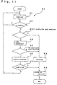
- Fig. 11 is a flowchart indicating a position detecting process.
- Fig. 1 shows an outlined configuration of a time measuring apparatus which can perform automatic time correction by the use of a position detecting function according to the present invention.
- the time measuring apparatus 1 according to the present embodiment is equipped with a stepper motor 2 for moving hands and a driving circuit (DRI) 3 for driving the stepper motor 2.
- the driving circuit 3 conducts normal time display with the use of 1-Hz driving pulses and can perform fast forward of hands with the use of fast-forward pulses having a frequency of 32 Hz or the like.
- the stepper motor 2 can drive a second hand 11, a minute hand 12, and an hour hand 13 by the use of a wheel train 10.
- the stepper motor 2 drives a fifth wheel 15 through a pinion and then drives, a fourth wheel 16, a third wheel (not shown), a center wheel 17, a back-side wheel (not shown), and an hour wheel 18 in this order.
- the second hand 11 moves together with the fourth wheel 16, the minute hand 12 moves together with the center wheel 17, and the hour hand 13 moves together with the hour wheel 18.
- Surfaces 16a, 17a, and 18a of the fourth wheel 16, the center wheel 17, and the hour wheel 18 have the same function as an encoder plate.
- an identification pattern 20 having the specified identification marks is made by the use of hard magnetic thin film such as magnetic ink.
- magnetic sensors 21a, 21b, and 21c serving as identification-mark detecting apparatuses are disposed opposite the magnetic pattern (identification pattern) 20, at positions where whether the identification marks of the identification pattern 20 are provided can be detected.
- the detection signal ⁇ 0 of each of these magnetic sensors 21a, 21b, and 21c is analyzed in an identification section 5, and the absolute positions (indicated positions) where the magnetic sensors 21a, 21b, and 21c oppose the encoder surfaces 16a, 17a, and 18a are identified.
- the indicated positions are output to a control section (CON) 6.
- the control section 6 uses the motor driving circuit 3 to fast forward the hands according to the positions of the hands, and perform automatic time correction according to a signal ⁇ 1 sent from the outside and indicating the standard time. Of course, it is possible to reverse the hands 11, 12, and 13 by providing a reverse function for the motor driving circuit 3.
- the control section 6 receives a clock signal from an oscillation circuit (OCI) 7. The control section 6 fast forwards the hands according to this clock signal and moves the hands normally according to the clock signal after the time is corrected.
- OCI oscillation circuit
- the detection signals ⁇ 0 output from the magnetic sensors 21a, 21b, and 21c disposed opposite the encoder surfaces 16a, 17a, and 18a are handled by three determination sections (JUD1) 23, (JUD2) 24, and (JUD3) 25 provided for the identification section 5.
- These determination sections 23, 24, and 25 manipulate data and send it to a decoder section (DEC) 27.
- DEC decoder section
- the decoder section 27 identifies the indicated positions on the encoder surfaces 16a, 17a, and 18a among the accumulated data group according to a code table stored in a ROM 28, and outputs information concerning the detected positions to the control section 6.
- the decoder section 27 reads (samples) data in synchronization with the timing of the movement of the encoder surfaces 16a, 17a, and 18a which are rotated stepwise by the stepper motor 2.
- the identification section 5 is provided with a timing adjustment circuit (DEL) 29 which sets a delay time for a driving signal sent from the control section 6 to the motor driving circuit 3, data sampling timing can be controlled against the timing at which the control section 6 drives the motor through the motor driving circuit 3.
- DEL timing adjustment circuit
- the identification section 5 is equipped with a reference-signal output section (REF) 26 for outputting a reference signal used for determining detection signals in the determination sections 23, 24, and 25.
- the reference-signal output section 26 receives a signal output from a magnetic sensor 22 disposed at a position away from the encoder surfaces 16a, 17a, and 18a.
- the level of a reference signal sent from the reference-signal output section 26 is compensated for by the use of a detection result of the magnetic sensor 22 to remove the effects of surrounding conditions such as noise and temperature changes.
- Fig. 2 illustrates a detailed configuration of the determination sections 23, 24, and 25, and the reference-signal output section 26. Since the determination sections 23, 24, and 25 can employ the same configuration, only the determination section 24, which identifies the position of the encoder surface 17a moving together with the minute hand 12, is shown in Fig. 2 as an example.
- the determination section 24 includes an amplifying circuit 31 for amplifying a detection signal sent from the magnetic sensor (SEN) 21b and for calibrating a difference among magnetic sensors, and a determination circuit 32 for determining whether an identification mark is provided by the use of the amplified detection signal.
- SEN magnetic sensor
- the amplifying circuit 31 of the present embodiment has a single-end conversion circuit (COV) 33 for converting the differential voltage of the detection signal ⁇ 0 obtained from the magnetic sensor 21b to a voltage relative to the reference voltage of a reference signal ⁇ 2 sent from the reference-signal output section 26, and a preamplifier (AMP) 34 for further amplifying the voltage amplified by the single-end conversion circuit 33. Since the differential voltage of the detection signal ⁇ 0 obtained from the magnetic sensor 21b is very small, the single-end conversion circuit 33 converts the differential voltage to a detection signal having a voltage difference based on the reference voltage of the reference signal ⁇ 2, and at the same time amplifies the output voltage by a factor of about 2 to 100 times.
- COV single-end conversion circuit
- AMP preamplifier
- the voltage of the reference signal ⁇ 2 sent to the single-end conversion circuit 33 can be adjusted to any level.
- the voltage of a reference signal ⁇ 3, which gives a reference voltage to be amplified by the preamplifier 34, can be fixed to a voltage different from that of the reference signal ⁇ 2 sent from the reference-signal output section 26 to the single-end conversion circuit 33. Therefore, by adjusting the voltage of the reference signal ⁇ 2 used in the single-end conversion circuit 33 by the reference-signal output section 36, the voltage not including an offset component generated in the differential voltage of the detection signal ⁇ 0 obtained from the magnetic sensor 21b can be amplified in the preamplifier 34.
- the preamplifier 34 includes an amplification-factor adjustment circuit, a sensitivity difference of the magnetic sensor 21b, a mounting condition against the encoder surface 17a, and a variation in strength of the detection signal ⁇ 0 caused by the condition of the identification marks put on the encoder surface 17a can be calibrated by adjusting the amplification factor.
- a difference in the characteristics of magnetic sensors and a difference in mounting conditions against the encoder surfaces are calibrated and detection signals ⁇ '0 amplified based on the specified voltage level can be obtained.
- the determination circuit 32 which determines from a detection signal whether an identification mark is provided, has two comparison circuits 35 (COP1) and 36 (COP2).
- the detection signals ⁇ '0 amplified based on the specified voltage level is compared with a first reference signal ⁇ 4 and a second reference signal ⁇ 5 in the comparison circuits 35 and 36, respectively.
- the first and second reference signals ⁇ 4 and ⁇ 5 are sent from the reference-signal output section 26, and the first reference signal ⁇ 4 is set to a higher voltage than the second reference signal ⁇ 5 in this embodiment.
- the comparison circuits 35 and 36 output a high-level signal when the detection signal ⁇ '0 is higher in voltage than the first and second reference signals ⁇ 4 and ⁇ 5, and output a low-level signal when the detection signal ⁇ '0 is lower in voltage than the first and second reference signals ⁇ 4 and ⁇ 5.
- the outputs of the comparison circuits 35 and 36 are sent to the decoder section 27.
- the decoder section 27 receives two high-level signals from both comparison circuits 35 and 36, it gets a first data, which indicates that it is confirmed that an identification mark is provided.
- the first data is hereinafter indicated by "1.”
- the decoder section 27 gets a second data, which indicates that it is confirmed that no identification mark is provided.
- the second data is hereinafter indicated by "0.” Since a voltage difference is set between the reference signals ⁇ 4 and ⁇ 5 for the comparison circuits 35 and 36, a case may happen in which the comparison circuit 35 outputs a low-level signal and the comparison circuit 36 outputs a high-level signal.
- the decoder section 27 handles this case with a third data, which indicates that it cannot be confirmed that an identification mark is provided.
- the third data is hereinafter indicated by "*.” As described above, with the use of the determination circuit 32, a detection signal which is detected by the magnetic sensor 21b can be classified into three cases.
- Reference signals ⁇ 2, ⁇ 3, ⁇ 4, and ⁇ 5 used for classifying a detection signal as described above are sent from the reference-signal output section 26.
- the reference-signal output section 26 in the present embodiment includes a reference-voltage generator (GEN) 41 for generating a plurality of reference signals having various voltages.
- Reference signals ⁇ 2 and ⁇ 3, sent from the reference-voltage generator 41 are used for adjusting the ground voltages of the single-end conversion circuit 33 and the preamplifier 34. By adjusting these two ground voltages, the preamplifier 34 amplifies the voltage with an offset voltage generated at a magnetic field of zero by the magnetic sensor 21b being removed.
- the reference-voltage generator 41 also outputs the first and second reference signals ⁇ 4 and ⁇ 5, which are used for comparison in the comparison circuits 35 and 36.
- these first and second reference signals ⁇ 4 and ⁇ 5 are sent to the comparison circuits 35 and 36 through an adder (ADD) 46.
- the adder 46 increases or reduces the voltage levels of the first and second reference signals ⁇ 4 and ⁇ 5 according to the increase or decrease of the output voltage of the magnetic sensor (R-SEN) 22 mounted at a position away from the encoder surfaces 16a, 17a, and 18a in order to prevent the effects of external noise and temperature.
- the reference-signal output section 26 is provided with a compensation circuit 42 for compensating for the voltage levels of reference signals.
- the compensation circuit 42 includes an amplifying circuit 43 formed by a single-end conversion circuit (COV) 44 for calibrating the detection output of the magnetic sensor 22 and for amplifying it in the same way as described above, and a preamplifier (AMP) 45.
- a compensation signal ⁇ 6 output from the preamplifier 45 is sent to the adder 46, and the voltage levels of the reference signals ⁇ 4 and ⁇ 5 are adjusted in the adder 46.
- the magnetic sensor 22, which sends a detection signal to the compensation circuit 42, is mounted at a position away from the wheel on which hard-magnetic thin film constituting an identification mark is formed.
- the electric signal output from the magnetic sensor 22 is changed only by a magnetic field from the outside of the timepiece.
- the signal amplification rate of the single-end conversion circuit 44 in the compensation circuit 42 is set equal to that of the single-end conversion circuit 33 in the determination section 24.
- the signal amplification rate of the preamplifier 45 in the compensation circuit 42 is also set equal to that of the preamplifier 34 in the determination section 24.
- a circuit formed by the magnetic sensor 21b, the single-end conversion circuit 33, and the preamplifier 34 in the determination section 24 has nearly the same temperature characteristics as a circuit formed by the magnetic sensor 22, the single-end conversion circuit 44, and the preamplifier 45 in the compensation circuit 42.
- the difference between the outputs of two preamplifiers 34 and 45 hardly changes due to the temperature. Therefore, by adding the output of the preamplifier 45 to the reference voltages of reference signals ⁇ 4 and ⁇ 5 in the adder 46, the effects of the temperature on the detection signal output from the magnetic sensor 21b can be almost canceled in the comparison circuits 35 and 36.
- the output of the preamplifier 34 greatly changes due to this external magnetic field.
- the compensation circuit 42 since the output of the preamplifier 45 in the compensation circuit 42 also changes by the same voltage change as that of the preamplifier 34, and the voltages of reference signals ⁇ 4 and ⁇ 5 also change at the same time, the comparison circuits 35 and 36 can accurately detect only magnetic information obtained from the hard-magnetic thin film without the effects of the external magnetic field.
- the magnetic sensor 22 which captures changes in the environmental conditions of the time measuring apparatus at a position away from the wheels, has substantially the same characteristics as the magnetic sensor 21b of the identification-mark detecting apparatus against the same objects to be measured, and can receive external magnetic noise applied to the magnetic sensor. Therefore, since an output including the noise is obtained from the preamplifier 45 of the compensation circuit 42, a change corresponding to the noise can be added to reference signals ⁇ 4 and ⁇ 5 in the adder 46, and the effects of the noise can be removed when a detection signal ⁇ 0 is classified.
- the reference-signal output section 26 of the present embodiment is provided with the magnetic sensor 22 for detecting only effects from the outside of the time-measuring apparatus, a changing component due to the effects of the outside environment can be removed from the detection signal of the magnetic sensor 21 for detecting an identification mark. Therefore, an identification mark can be precisely detected under any conditions.
- reference signals ⁇ 4 and ⁇ 5 even when the detection signal ⁇ 0 of the magnetic sensor 21b is controlled according to the output of the compensation circuit 42, effects from the outside environment can be removed.
- the voltage levels of reference signals ⁇ 2, ⁇ 3, ⁇ 4, and ⁇ 5 output from the reference-voltage output circuit 41 can be adjusted separately as required, the voltages of reference signals ⁇ 4 and ⁇ 5, which are used in the comparison circuits 35 and 36, can be adjusted according to the output voltage of the preamplifier 34, and the voltage levels of reference signals can be changed in a case when accurate detection becomes difficult in the comparison circuits 35 and 36 due to the temperature and other factors changing with the passage to time.
- the determination section 24 which serves as a circuit for determining the position of the minute hand 12, is shown and it has been described.
- the configuration of the determination section 25 for determining the position of the second hand 11 and that of the determination section 23 for determining the position of the hour hand 13 are the same as that of the determination section 24.
- the reference-signal output section 26 sends reference signals also to the determination sections 23 and 25, and reference signals used in each comparison circuit are also compensated for in the same way.
- the voltages of reference signals are controlled by the output of the compensation circuit 42 for compensating for effects from the outside environment. It is needless to say that the voltage of the detection signal ⁇ '0 may be compensated for.
- a constant-voltage circuit is provided for the time measuring apparatus 1 of the present embodiment. The constant-voltage circuit supplies power to each of the above circuits.
- Fig. 3 shows an identification pattern marked on the encoder surface 17a and used for detecting the position of the minute hand 12 as an example of identification patterns 20 marked on the encoder surfaces 16a, 17a, and 18a.
- An identification pattern 20 of the present embodiment is formed on the surface of the center wheel 17.
- Nine identification marks 50a to 50i are disposed discretely along the circumference of the disc-shaped encoder surface 17a. These identification marks 50a to 50i are detected at sampling points (ideal sampling points) 51 made at a pitch of six degrees, by the magnetic sensor 21b in which a Hall device is used.
- This identification pattern 20 can be formed by hard-magnetic film made by magnetic ink.
- a magnetic sensor for detecting the pattern can be formed by a GaAs Hall device and can be made as very small as a 300- ⁇ m square. Therefore, the position detecting function of the present embodiment can easily be incorporated into the movement of the time-measuring apparatus 1.
- a detection mechanism for detecting hand positions can be integrated without changing the size of the time-measuring apparatus 1 at all, such as the thickness and the diameter. Since a position can be detected without any contact between the magnetic sensor 21b and the identification pattern 20 by employing a combination of a Hall device and the identification pattern formed by magnetic film, hands are moved without problems and design changes are unnecessary, such as changing the stepper motor 2 and the characteristics of the wheel train 10.
- Each of the identification marks 50a to 50i constituting an identification pattern 20 are disposed radially from the center of the encoder surface 17 and magnetized in the direction perpendicular to the encoder surface. An indicated position where the magnetic sensor 21b faces the encoder surface 17a can be recognized by an absolute value.
- identification mark 50a covers from 1 to 9 degrees
- identification mark 50b covers from 25 to 69 degrees
- identification mark 50c covers from 85 to 105 degrees
- identification mark 50d covers 121 to 153 degrees
- identification mark 50e covers from 169 to 177 degrees
- identification mark 50f covers from 193 to 201 degrees
- identification mark 50g covers 253 to 261 degrees
- identification mark 50h covers from 289 to 297 degrees
- identification mark 50i covers 337 to 345 degrees.
- the ideal sampling points 51 are specified at a pitch of 6 degrees from point 01 which is positioned at two degrees to point 60.
- Fig. 4 shows a detection signal ⁇ '0 obtained by amplifying in the preamplifier a signal sent from the magnetic sensor 21b in a case when the encoder surface 17a on which the identification pattern 20 is marked is rotated at a pitch of six degrees.
- the signal level of the detection signal ⁇ '0 shown in Fig. 4 is indicated by an output voltage.
- the signal level is adjusted by the amplifying circuit 31 of the determination section 24 such that it changes within a range of -20 mV to 40 mV.
- Fig. 5 shows a data group (identification codes, reference sampling codes) 59 to be obtained at the ideal sampling points 01 to 60 when the magnetic sensor 21b detects the identification pattern 20 while the encoder surface 17a is rotated.
- the identification pattern 20 of the present embodiment is specified such that a total of 12 data values including the currently sampled data value and the 11 preceding sampling data values form a reference sampling code to identify the current point from points 01 to 60. Therefore, each identification code (reference sampling code) 59 shown in Fig. 5 is unique.
- a data group (sampling code) including 12 data items is decoded in the decoder section 27 by comparing it with the identification codes 59 shown in Fig. 5 and stored in advance in the ROM 28 to detect the indicated position as an absolute position.
- the identification pattern 20 of the present embodiment is specified as understood from Fig. 3 or Fig. 5 such that an even number of sampling points 51 are assigned to each of the identification marks 50a to 50i, and an even number of sampling points 51 are assigned to a space 52 between two of the identification marks 50a to 50i.
- each of the identification marks 50a to 50i has a size in which an even number of sampling points 51 are included, and each identification mark is disposed with spaces 52 having an even number of sampling points 51 placed at both sides.
- the identification marks 51a to 50i are specified such that two boundaries 53 between the identification marks 51a to 51i and the spaces 52 must exist within the points corresponding to the identification code for each of the points 01 to 60.
- the identification pattern 20 of the present embodiment is specified such that the identification codes 59 are formed by data obtained at 12 sampling points 51, and sampling is performed at these 12 successive sampling points 51 with two boundaries 53 being passed through.
- each identification code 59 includes data sampled at all points in at least one of the identification marks 50a to 50i or at least one of the spaces 52 between the identification marks.
- each identification code 59 corresponding to each of the points 01 to 60 includes a data string in which an even number of "0's” or “1's” are arranged, excluding the start and end data strings.
- each identification code 59 has two or more combinations of a transition from “0” to “1” or a transition from “1” to “0”, and an even number of "0's” or “1's” exist between transitions. Therefore, with the use of rules in the identification codes, element "*,” which indicates that data is indefinite, can be corrected in a sampling code having "*" by the number of data values "0" or “1” arranged before and after "*" in the data string.
- the sampling method and the rules of the identification codes can be used for correcting a sampling code when the phase shifts between a position where the wheel on which the identification pattern 20 formed by hard-magnetic thin film is marked stops and the magnetic sensor 21b for detecting a magnetic field, in other words, when an actual sampling point shifts from the corresponding ideal sampling point 51 specified when the identification pattern 20 is designed.
- An indicated position can be precisely detected within a short period of time.
- the encoder plates (encoder surfaces) equipped with the identification pattern 20 in which an even number of sampling points are included are used. It may be possible to employ encoder plates (encoder surfaces) equipped with an identification pattern in which an odd number of sampling points are included, or an odd number of sampling points in identification codes and an even number of sampling points in spaces are specified, or vice versa.
- To use the rules specified for an odd number of sampling points it is required to include an odd number three or above of sampling points because, when there exists only one sampling point, if data obtained at the point becomes indefinite, it cannot be determined. Therefore, when an odd number of sampling points are used, since the amount of data included in sampling codes tends to increase, identification processing needs much time. It is hence preferred that the rules specified for an even number of sampling points be employed in a position detecting apparatus in which about 60 sampling points are specified for a time-measuring apparatus.
- Fig. 6 shows the voltage changes of the detection signal ⁇ '0 output from the magnetic sensor and amplified by the preamplifier 34, at the average stop position R7 for the specified sampling point on an encoder surface, namely, a wheel, and at the average stop position R8 of the next sampling point.
- An average stop position is specified at an average temperature (for example, at about 25°C) for the use of the time measuring apparatus 1 with an average phase between a wheel provided with an encoder surface, for example, the center wheel 17, and the magnetic sensor 21b, and an average distance caused by the forcible movement and waviness of the wheel.
- the ideal sampling points 51 are specified with these average stop positions being set to the targets.
- the voltage of the detection signal ⁇ '0 obtained from the preamplifier 34 changes due to variation in the distance between the encoder surface 17a and the magnetic sensor 21b caused by the forced movement and waviness of the wheel 17, a change in the strength of the magnetic field of the hard-magnetic thin film which forms the identification pattern 20 caused by a temperature change at sampling, and a change in the magnetic sensitivity of the magnetic sensor 21b. Therefore, due to these various factors, the output of the detection signal ⁇ '0 at the specified sampling point may vary in the hatched range in the figure against the outputs obtained at average stop positions R7 and R8.
- the voltage (signal level) of the detection signal ⁇ '0 may decrease, although ideally the signal has a high level, namely, "1.” Conversely, the voltage (signal level) of the detection signal ⁇ '0 may increase, although ideally the signal has a low level, namely, "0.”
- a sampling code of "001110111111” is obtained at point 10. It is found from a rule of the identification codes that an even number of "1's” or "0's” are arranged that the obtained sampling code has an erroneous detection, and it is determined from the fact that at least two boundaries 53 are included that the fifth data value is erroneous and it must be "0.” However, when the level corresponding to the sixth data value decreases at point 24 and a sampling code of "001110001111" is obtained, for example, it is found that there is an erroneous detection, but the position of the data erroneously detected cannot be determined and hence the erroneously detected data value cannot be corrected.
- the signal level of the detection signal ⁇ '0 is determined by the use of two reference signals ⁇ 4 and ⁇ 5 having a voltage difference (signal-level difference) in the two comparison circuits 35 and 36. Therefore, in the above case at point 24, for example, a sampling code of "00111*001111" is obtained. Since the position of erroneous data value can be determined in the determination section 24 of the present embodiment, an identification code which is the nearest to the sampling code can easily be specified.
- the determination section 24 which uses two reference signals ⁇ 4 and ⁇ 5
- the indicated position can be identified with the small number of the sampling points in this way. Therefore, the determination section of the present embodiment is especially effective for detecting the positions pointed by the hour hand 13 and the minute hand 12 for which much time is required to increase sampling points, unlike the second hand 11. Since the hour hand 13 moves together with the second hand 11 and the minute hand 12, a long time is required to perform fast-forward of the hour hand in order to obtain the specified sampling code.
- the positions of the hands can precisely be identified within a short period of time.
- the stop position R8 is a sampling point
- the data to be obtained as a detection result is "1,” it is required to set the voltage of reference signal ⁇ 5 such that value "0" is not output even if the detection signal ⁇ '0 changes due to various factors.
- the level of the first reference signal ⁇ 4 be set to larger than the maximum value of the detection signal ⁇ '0 output by the magnetic sensor at a sampling point where an identification mark does not exist
- the level of the second reference signal ⁇ 5 be set to smaller than the minimum value of the detection signal ⁇ '0 output by the magnetic sensor at a sampling point where an identification mark exists.
- Data which is not determined in a sampling code may not be error-corrected because an identification code which has the shortest distance to the sampling code cannot be found.
- a sampling code of "**1100110011” is obtained, for example, possible identification codes include those at points 34 and 06, but the real identification code cannot be identified.
- the next data is "0,” for example, the identification code at the next sampling point is "*11001100110" and it is found from the last 11 bits although the first data is not determined that the code matches the identification code at point 35.
- the identification code having the shortest distance to a sampling code at the next sampling point 51 is not found, it is required to perform further sampling continually.
- This method is effective not only for a case in which an identification code is not uniquely determined from the detected sampling code, but for confirming the recognized identification code to increase the reliability of the detected data. By repeating sampling, since obtained data becomes redundant, error correction can be easily performed, and the indicated positions can be detected even when undetermined data increases.
- the positions of the hands thereafter can be controlled with the use of a pulse count method in which the number of steps the stepper motor 2 operates from the determined positions is referred. Therefore, in the time-measuring apparatus 1, an identification mark is detected at a plurality of sampling points to form a sampling code and, from the point of time when a sampling code from which the positions of the hands are determined is obtained, control is changed to hand-position control by the number of steps the stepper motor 2 operates.
- the time-measuring apparatus is one of electronic apparatuses to which a position detecting apparatus and a position detecting method according to the present invention are applied to identify the positions of hands.
- a position detecting apparatus and a position detecting method of the present invention even in a compact time-measuring apparatus such as a watch, the absolute positions of hands can be identified at any time.
- the position which the minute hand 12 points is estimated to some extent from the position which the hour hand 13 points. Therefore, by comparing the estimated sampling code which indicates the estimated position which the minute hand 12 points with the obtained sampling code, the indicated position on the encoder surface 21b (sub encoder) for the minute hand 12 can easily be identified with a few sampling data values, or sampling data having many errors.
- the range of identification codes (reference sampling codes) with which the obtained sampling code is compared can be limited. Therefore, if a plurality of undetermined data values "*" is included, since the range of identification codes to be compared is narrow, the indicated position can be identified.
- the above sampling code "**1100110011” is obtained as a sampling code for the minute hand 12, for example, and it has been found that the position of the hour hand 13 decoded in advance is located within a 30-minute (exclusive) position, it is easy to determine that the indicated position is point 34. Decoding becomes easier by increasing the number of sampling points or by limiting the range of identification codes to be compared with from the pointed position pointed by another hand. Therefore, although the sampling time extends, the pointed position can be identified even with the use of an identification pattern from which data having no rules is obtained as described above as identification codes.
- the encoder surface 16a which is one of the encoder surfaces of the present embodiment and indicates the position pointed by the second hand, is driven by the stepper motor 2 step by step. Therefore, the encoder surface 16a roughly moves from a certain sampling point to the next sampling point as shown in Fig. 9. Assume that sampling points of the magnetic sensor 21a shift from average stop positions (ideal sampling points) R7 and R8 counterclockwise to R'7 and R'8 as shown in Fig. 8. In this case, it is highly possible that data obtained from the detection signal ⁇ 1 sampled at R'8, which is close to a boundary 53, becomes indefinite "*" as described above. In contrast, the wheel 16 is moved by the stepper motor 2 for about 30 to 40 ms as shown in Fig.
- the identification section 5 of the present embodiment is provided with a timing adjustment circuit 29.
- the circuit finds from the control section 6 that motor driving pulses shown in Fig. 10 are output, and can specify in advance 10 to 20 detectable timing points during the period from when the pulses are output to when the wheel stops. Therefore, by specifying sampling timing such that sampling codes having the least number of indefinite data values are obtained, whether identification mark 50 is provided or not can be detected at the same precision as in a case when the encoder surface stops at an ideal sampling point 51.
- a timing adjustment circuit 29 and adjusting timing at the sampling side troublesome work can be eliminated such as fine adjustment of a wheel stop position and fine adjustment of the position of the magnetic sensor 21.
- timing it is not necessary to select timing again unless the wheel stop position changes due to some factor. Since the phase relationship between the encoder plate and the magnetic sensor at each sampling point is nearly the same, it is not necessary to select timing at each sampling point, and more precise sampling codes can be obtained by setting nearly equal the interval from when motor driving pulses are output to each sampling.
- the number of sampling data can be increased by setting a sampling timing interval shorter than the time corresponding to the resolution of the indicated positions, error correction becomes easier to achieve and more precise position detection is performed. It is required in terms of knowing the hour of the time to find which 12 divided position the hour hand 13 points. With the use of the above-described identification pattern, the indicated position can be identified with 60 divided sampling points. Therefore, the distance the hour hand is moved for determining the position can be shortened against the resolution of the hand, and highly precise data is obtained within a short period of time.
- timing adjustable period differs according to the rotation speed of an encoder plate, it is needless to say that the same advantages are obtained.
- Fig. 11 shows a process for detecting an indicated position by the use of the identification section 5 of the present embodiment.
- Fig. 11 shows a process for detecting the position pointed by the minute hand. Since the decoding method in which the position of the hour hand is taken into consideration can be employed as described above to decode the position of the minute hand, Fig. 11 shows such a case.
- the position detecting method shown below as an example can also be used for that for the position pointed by the second hand or the minute hand if step 66, which performs limited decoding for a sub encoder surface, is excluded.
- sampling of the identification patterns by the use of the magnetic sensor 21b starts in step 61 while the encoder plate (encoder surface) 17a is rotated.
- sampling may be performed at the specified angle (sampling point) while the encoder plate 17a is continually rotated or at a stable position after the encoder plate is rotated by one-step angle.
- sampling can be performed in an intermediate condition between these two conditions.
- a detection signal from the magnetic sensor 21b is classified into a first data "1" indicating it is confirmed that an identification mark is provided, a second data "0” indicating it is confirmed that no identification mark is provided, or a third data "*" indicating that it cannot be confirmed that an identification mark is provided, in the determination section 24.
- step 62 it is determined whether n samples are obtained to form a sampling code, and step 61 is repeated until n samples are obtained.
- a sampling code since a sampling code has 12 bits, it is necessary to obtain 12 samples.
- step 63 whether indefinite data "*" is included in the sampling code is determined in step 63.
- step 68 the process advances to step 68 since there is no erroneously detected data in the sampling code, and the obtained sampling code is decoded by the use of identification codes shown in Fig. 5 and recorded in the ROM 28 of the decoding section 27 to determine the indicated position.
- the identified indicated position is output to the control section 6, and the control section 6 performs automatic time correction and other processes according to the identified hand positions.
- step 64 If the third data "*" indicating indefinite is included in the sampling code, with the use of the rules for the number (even number) of data "1's" and that of data "0's" in an identification code as described above, error correction is performed in step 64 and the corrected sampling code is created. After error correction, whether the corrected sampling code includes the third data "*" indicating indefinite is determined in step 65. When the third data "*" is not included, since the sampling code has been corrected and the correct sampling code is obtained, the processing proceeds to step 68 and the indicated position is decoded as described above.
- step 66 the sampling code is compared with limited identification codes according to the position pointed by the hour hand 13 and decoded.
- Step 66 which performs limited decoding, is executed when a position determining process for determining the position pointed by the hour hand 13 was performed and the position pointed by the hour hand 13 has been identified.
- the encoder surface 17a of the minute hand 12 is a sub encoder surface moving together with the encoder surface 18a of the hour hand 13, and the designated position on the encoder surface 17a can be limited according to the designated position on the encoder surface 18a.
- identification codes to be compared in the decoder section 27 can be limited as described above, even a sampling code having the third data "*" may be decoded.
- the decoding result is checked in step 67.
- the processing proceeds to step 69 and the identified indicated position is output to the control section 6.
- step 67 When the indicated position is not identified from the sampling code even in the process in step 67, the processing returns to step 61. Data at the next sampling point is obtained and the foregoing steps are repeated until the indicated position is identified. Even when the indicated position is identified, it is possible to increase the reliability of the indicated position by repeating sampling to identify a plurality of indicated positions and determining whether those indicated positions are acceptable to each other.
- the time-measuring apparatus 1 of the present embodiment can automatically recognize the positions pointed by the second hand 11, the minute hand 12, and the hour hand 13 by the use of the identification section 5. Therefore, according to the recognized pointed positions, automatic time correction can be performed with fast-forward operation and other processing. It is possible to incorporate into the time-measuring apparatus 1 of the present embodiment a function for recovering the current time after the time display has been stopped, a function for automatically correcting the time to the standard time in a zone in which the standard time is different from that in the original zone, and a function for compensating for a shift from the standard time.
- the identification section 5 which performs position detection described above, can be configured with a special logical gate IC and other components by hardware.
- An identification portion according to the present invention is not limited to this identification section. It may be a unit provided with functions described in the claims of the present invention. It is also possible to achieve the function of an identification portion with the use of a microprocessor and a program having instructions for executing each process in the position detecting process 60 described above. This position detecting program can be recorded in a recording medium such as the ROM 28 from which data is read to the processor, and accommodated in the time-measuring apparatus or offered.
- the identification portion is implemented by software, it is preferred that the detection signal from the magnetic sensor be amplified and digitally converted to a condition suited for software processing.
- the apparatus can easily be incorporated into a compact, lightweight apparatus such as a watch.
- a time-measuring apparatus which moves hands by the use of a single motor is described.
- the hands can be moved by a plurality of motors.
- the processes for detecting the positions pointed by the second hand, the minute hand, and the hour hand can be started at the same time.
- the encoders are moved.
- the sensors may be moved instead to determine the indicated positions. Both encoders and sensors may be moved to identify the indicated positions.
- the above-described identification pattern is just an example.
- An identification pattern according to the present invention is not limited to this pattern.
- an identification mark can employ a rule in which an odd number of sampling points are given. In this case, it is necessary to assign at least three sampling points to one identification mark with indefinite data being taken into consideration.
- hard-magnetic thin film is used to apply the identification patterns to the encoder plates. Instead of the magnetic film, magnetic paste may be placed on the encoder plates to form identification patterns.
- optical identification patterns such as reflective ones may be provided to detect the identification patterns optically with an optical pickup. Other detection methods can also be employed.
- the position of the hour hand, the minute hand, or the second hand which is a display unit of the time-measuring apparatus, is detected.
- the present invention is not limited to the time-measuring apparatus. It can also be applied to a display apparatus such as a rotation-type speedometer, and position detection and control for a linear-movement apparatus, such as positioning of the printer head of a printer.
- a display apparatus such as a rotation-type speedometer, and position detection and control for a linear-movement apparatus, such as positioning of the printer head of a printer.
- analog speedometers have been used for many vehicles. There are usually an error between the indicated speed and the actual speed.
- the speed indication can be compensated for its error.
- the reliability of the speedometer is improved and highly precise speed indication can be made possible especially for a vehicle to which tires other than the specified types of tires, that may increase errors in speed indication, are mounted.
- a time-measuring apparatus provided with a compensation function and a compensation apparatus can be offered in which hand-movement positional information obtained by a motor-pulse count method with the use of an IC is periodically compared even in usual hand movement with hand-movement positional information obtained from hand-position detection according to the present invention, and if a difference is found, it is determined that hand movement has an error and the indicated position is compensated.
- the encoder plates on which a plurality of identification marks are discretely made such that the marks are detectable from the surfaces thereof are employed and absolute positions are detected by a plurality of sampling operations for the identification marks while the encoder plates are rotated.
- the third data which indicates that identification marks are not confirmed is provided so as not to interpret an indicated position erroneously due to data in which the identification marks are erroneously detected.
- the third data which is indefinite, can be error-corrected. Therefore, even if a part of the identification marks are not detected in the position detecting apparatus of the present invention, the correct position can be identified within a short period of time without additional sampling.
- a position detecting apparatus and a position detecting method it is required to prepare one-bit data at each sampling point. Sampled data is combined to form a sampling code and the code is decoded. Correct, absolute indicated positions can be detected. Therefore, an identification-mark detecting apparatus for detecting identification marks needs to have one sensor, and thereby the configuration of the position detecting apparatus is very simplified and its reliability is improved.
- the relative movement speed of the encoder plates may be low. Even if the encoder plates are moved step by step, since data indicating the indicated position is obtained, they are suited to a compact, portable apparatus such as a watch. It is also possible to integrate a function for detecting the hand positions of the time-measuring apparatus for automatic time correction.
- an indicated position is determined from a sampling code obtained at a plurality of sampling points, an erroneous position is not identified even if data indicating erroneous detection is included in the sampling code.
- a detecting method can be employed in which error correction is performed first with the use of the rules of identification marks, and then a position is decoded. Therefore, an indicated position can be positively identified within a short period of time.
- a detecting apparatus for detecting environmental conditions which has the same characteristics as the detecting apparatus for an identification mark, is provided to compensate the strength of reference signals used for classifying a sampled detection signal, according to a change in the environmental conditions. Therefore, an identification mark can be correctly detected with the effects of a temperature change and external noise being eliminated, and highly precise information can be obtained. Since a position detecting apparatus of the present invention is provided with means for eliminating a difference caused by assembling errors by adjusting the sampling timing, an indicated position can be positively determined within a short period of time.
- a position detecting apparatus and a position detecting method according to the present invention identify the absolute positions of a hand and others with a simple configuration, they are very suited to automatic recognition of the positions of a compact apparatus such as a time-measuring apparatus and a display unit of a portable apparatus. According to the results, compensation and time correction can also be suitably performed.
Abstract
Description
indicating that it cannot be confirmed that an identification mark is provided, and a decoder for decoding a sampling code, which is a plurality of data groups, formed by any of the first, second, or third data obtained from the identification-mark determination apparatus to identify an indicated position. By outputting the third data which indicates that it cannot be confirmed that an identification mark is provided, the decoder can identify an indicated position while the encoder plate is moved, until a sampling code not having the third data is obtained. It may be performed that a relatively long sampling code including a redundant bit is obtained and an indicated position is identified from the first and second data with the third data being ignored. As described later, it is also possible that the third data is corrected by the use of data rules and a sampling code is decoded.
Claims (20)
- A position detecting apparatus comprising:an encoder plate on which a plurality of identification marks are discretely made such that said identification marks are detectable from a surface thereof;an identification-mark detecting apparatus which can detect said identification marks on said encoder plate; andan identification apparatus which can identify an indicated Position on said encoder plate which said identification-mark detection apparatus faces, according to a sampling code obtained by sampling sequentially at a plurality of sampling points to determine whether said identification marks are provided while said encoder plate and said identification-mark detecting apparatus are relatively moved.
- A position detecting apparatus according to Claim 1,
wherein said identification apparatus is provided with an identification-mark determination apparatus which outputs at each sampling point a first data indicating that it is confirmed that an identification mark is provided, a second data indicating that it is confirmed that no identification mark is provided, or a third data indicating that it cannot be confirmed that an identification mark is provided, and
a decoder for decoding a sampling code formed by any of said first, second, or third data obtained from said identification-mark determination apparatus to identify an indicated position on said encoder plate. - A position detecting apparatus according to Claim 2,
wherein said identification-mark detecting apparatus is provided with a sensor which can output a detection signal of which the signal level increases or decreases according to whether an identification mark is provided, and
said identification-mark determination apparatus is provided with a first comparison apparatus for outputting said first data when the detection signal from said sensor is higher than a first reference signal and a second comparison apparatus for outputting said second data when the detection signal from said sensor is lower than a second reference signal which is lower than said first reference signal. - A position detecting apparatus according to Claim 3,
wherein said first reference signal is higher than the maximum value of a detection signal output from said sensor when no identification mark is provided, and said second reference signal is lower than the minimum value of a detection signal output from said sensor when an identification mark is provided. - A position detecting apparatus according to Claim 3,
comprising: an environmental-condition detecting apparatus which can detect an environmental condition and has substantially the same characteristics as said identification-mark detecting apparatus for the same object to be measured, and
a compensation apparatus which can compensate the signal level of at least one of said first and second reference signals and said detection signal according to the detection result of the environmental-condition detecting apparatus. - A position detecting apparatus according to Claim 1,
wherein said encoder plate is provided with an identification mark including an even number of ideal sampling points where said sampling is to be performed with a space including an even number of said ideal sampling points being placed next to said identification mark, and
said identification apparatus can identify an indicated position on said encoder plate according to a sampling code sampled such that a plurality of boundaries between these identification mark and space are passed through. - A position detecting apparatus according to Claim 1,
wherein said encoder plate is provided with an identification mark including an even number or an odd number three or above of ideal sampling points where said sampling is to be performed with a space including an even number or an odd number three or above of said ideal sampling points being placed next to said identification mark, and
said identification apparatus can identify an indicated position on said encoder plate according to a sampling code sampled such that a plurality of boundaries between these identification mark and space are passed through. - A position detecting apparatus according to Claim 1,
comprising: a movement apparatus which can move said encoder plate in a step manner against said identification-mark detecting apparatus; and
a timing adjustment apparatus which can adjust sampling timing against the timing when said encoder plate is relatively moved. - A position detecting apparatus according to Claim 1,
wherein the resolution of the sampling point is smaller than that of the indicated position based on the position of said encoder plate. - A position detecting apparatus according to Claim 1,
wherein said encoder plate is moved together with at least any of the second hand, the minute hand, or the hour hand of a time-measuring apparatus. - A position detecting apparatus according to Claim 1,
wherein an identification mark is made on a surface of said encoder plate by magnetic thin film and said identification-mark detecting apparatus is provided with a magnetic sensor which can detect said magnetic thin film. - An encoder plate on which a plurality of identification marks are discretely made such that said identification marks are detectable from a surface thereof, wherein said identification marks including an even number of ideal sampling points where sampling is to be performed are made with a space including an even number of said ideal sampling points being placed therebetween, and
a plurality of boundaries between identification marks and spaces are passed through when an indicated position on said encoder plate is identified. - An encoder plate on which a plurality of identification marks are discretely made such that said identification marks are detectable from a surface thereof, wherein said identification marks including an even number or an odd number three or above of ideal sampling points where sampling is to be performed are made with a space including an even number or an odd number three or above of said ideal sampling points being placed therebetween, and
a plurality of boundaries between identification marks and spaces are passed through when an indicated position on said encoder plate is identified. - A position detecting method comprising a position detecting step in which against an encoder plate on which a plurality of identification marks are discretely made such that said identification marks are detectable from a surface thereof, an identification-mark detecting apparatus which can detect said identification marks is relatively moved, and an indicated position on said encoder plate which said identification-mark detection apparatus faces is identified according to a sampling code obtained by sampling sequentially at a plurality of sampling points to determine whether said identification marks are provided.
- A position detecting method according to Claim 14,
wherein said identification marks including an even number of ideal sampling points where said sampling is to be performed are made on said encoder plate with a space including an even number of said ideal sampling points being placed therebetween, and
said position detecting step includes a first step for obtaining at sampling points a first data indicating that it is confirmed that an identification mark is provided, a second data indicating that it is confirmed that no identification mark is provided, and a third data indicating that it cannot be confirmed that an identification mark is provided,
a second step for generating a sampling code by correcting said third data by the number of the first and second data disposed therebefore and thereafter, and
a third step for determining an indicated position on said encoder plate by decoding said sampling code. - A position detecting method according to Claim 14,
wherein said encoder plate is moved together with at least any of the second hand, the minute hand, or the hour hand of a time-measuring apparatus. - A position detecting method according to Claim 14,
further comprising, in addition to said position detecting step, a second position detecting step for identifying, according to a sampling code obtained by sequentially sampling to determine whether said identification marks are provided, at a plurality of sampling points on a sub encoder plate which moves together with said encoder plate and on which said identification marks are made such that they are detectable from a surface thereof, an indicated position on said sub encoder plate,
said second position detecting step including a step for identifying an indicated position on said sub encoder plate by comparing the obtained sampling code with limited reference sampling codes indicating the indicated position on said sub encoder plate, which is predicted from the indicated position on said encoder plate. - A position detecting method according to
Claim 17, wherein said encoder plate rotates together with the hour hand of a time-measuring apparatus and said sub encoder plate rotates together with the minute hand of said time-measuring apparatus. - A time-measuring apparatus comprising: a position detecting apparatus specified in Claim 1; and at least one of a second hand, a minute hand, and an hour hand; wherein at least one of said encoder plate and said identification-mark detecting apparatus rotates together with at least one of said second hand, said minute hand, and said hour hand.
- An electronic apparatus comprising: a position detecting apparatus specified in Claim 1; and a display apparatus which moves together with at least one of said encoder plate and said identification-mark detecting apparatus.
Applications Claiming Priority (4)
| Application Number | Priority Date | Filing Date | Title |
|---|---|---|---|
| JP13042296 | 1996-05-24 | ||
| JP130422/96 | 1996-05-24 | ||
| JP13042296 | 1996-05-24 | ||
| PCT/JP1997/001758 WO1997045705A1 (en) | 1996-05-24 | 1997-05-23 | Position detector, encoder board, position detecting method, timer and electronic device |
Publications (3)
| Publication Number | Publication Date |
|---|---|
| EP0841538A1 true EP0841538A1 (en) | 1998-05-13 |
| EP0841538A4 EP0841538A4 (en) | 1999-08-18 |
| EP0841538B1 EP0841538B1 (en) | 2003-02-19 |
Family
ID=15033876
Family Applications (1)
| Application Number | Title | Priority Date | Filing Date |
|---|---|---|---|
| EP97922167A Expired - Lifetime EP0841538B1 (en) | 1996-05-24 | 1997-05-23 | Position detector, encoder board, position detecting method, timer and electronic device |
Country Status (7)
| Country | Link |
|---|---|
| US (1) | US6038523A (en) |
| EP (1) | EP0841538B1 (en) |
| JP (1) | JP3440470B2 (en) |
| CN (1) | CN1133867C (en) |
| DE (1) | DE69719148T2 (en) |
| HK (1) | HK1017920A1 (en) |
| WO (1) | WO1997045705A1 (en) |
Cited By (8)
| Publication number | Priority date | Publication date | Assignee | Title |
|---|---|---|---|---|
| EP1256855A2 (en) * | 2001-05-11 | 2002-11-13 | Seiko Instruments Inc. | Hand position detecting apparatus for timepiece |
| EP1403623A1 (en) * | 2002-09-25 | 2004-03-31 | Dr. Johannes Heidenhain GmbH | Method for determining an absolute position |
| EP1422582A2 (en) * | 2002-11-21 | 2004-05-26 | Seiko Instruments Inc. | Hand position detecting apparatus and electronic timepiece using the same |
| EP1607808A1 (en) * | 2004-06-15 | 2005-12-21 | Asulab S.A. | Method for the synchronization of the analog display of a timepiece provided with an electronic timebase |
| US7440359B2 (en) | 2006-10-03 | 2008-10-21 | The Swatch Group Research And Development Ltd | Timepiece including means for determining the angular position of an analogue indicator of the timepiece |
| EP2333622A3 (en) * | 2009-12-10 | 2011-09-14 | Casio Computer Co., Ltd. | Hand position detecting device and electronic timepiece |
| WO2014154948A3 (en) * | 2013-03-28 | 2016-02-18 | Meta Watch Oy | Device with functional display and method for time management |
| CN110741231A (en) * | 2017-06-16 | 2020-01-31 | 株式会社电装 | Position sensor |
Families Citing this family (47)
| Publication number | Priority date | Publication date | Assignee | Title |
|---|---|---|---|---|
| JPH11211862A (en) * | 1997-11-19 | 1999-08-06 | Seiko Epson Corp | Information processor |
| DE69817764T2 (en) | 1998-04-24 | 2004-07-15 | Asulab S.A. | Clockwork with an inductive or capacitive sensor for the detection of at least one angle of rotation of a gearwheel within the clockwork |
| SG85647A1 (en) | 1998-06-29 | 2002-01-15 | Asulab Sa | Device including at least two coaxial wheels and means for detecting the angular position thereof and method for detecting said angular positions |
| DE69820423T2 (en) * | 1998-07-01 | 2004-10-14 | Asulab S.A. | Device and method for determining the angular position of at least two coaxial wheels with a single sensor |
| DE69942303D1 (en) * | 1999-05-06 | 2010-06-10 | Asulab Sa | Clock with means for determining the angular position of the coaxial pointer of an analog display |
| CN1132077C (en) | 1999-05-06 | 2003-12-24 | 阿苏拉布股份有限公司 | Clock with device for indicating angle position of coaxial analog display hand |
| DE10161854B4 (en) * | 2001-12-17 | 2005-01-13 | Eurochron Gmbh | Radio movement with detector for the pointer position |
| US20030113573A1 (en) | 2001-12-19 | 2003-06-19 | Pepin John Graeme | Thick film composition yielding magnetic properties |
| US7436737B2 (en) * | 2002-03-04 | 2008-10-14 | Citizen Holdings Co., Ltd. | Electric timepiece |
| TW558677B (en) * | 2002-08-02 | 2003-10-21 | Chih-Hao Yiu | Device for detecting angular position |
| CA2424790A1 (en) * | 2003-04-04 | 2004-10-04 | Evertz Microsystems Ltd. | Analog clock |
| JP3974893B2 (en) * | 2003-12-09 | 2007-09-12 | ファナック株式会社 | Encoder |
| JP2004157142A (en) * | 2004-03-01 | 2004-06-03 | Seiko Epson Corp | Timepiece device, and control method for the same |
| US7154818B2 (en) * | 2004-10-12 | 2006-12-26 | Ele Gancy Tleleancy Co., Ltd. | Radio controlled clock movement control system |
| SE529125C2 (en) * | 2005-03-02 | 2007-05-08 | Tetra Laval Holdings & Finance | Method and apparatus for determining the position of a packaging material with magnetic markings |
| US7463168B2 (en) * | 2006-07-21 | 2008-12-09 | Hewlett-Packard Development Company, L.P. | Encoder |
| DE102007045362A1 (en) | 2007-09-22 | 2009-04-02 | Dr. Johannes Heidenhain Gmbh | Position measuring device |
| JP4488049B2 (en) * | 2007-09-28 | 2010-06-23 | カシオ計算機株式会社 | Needle position detector |
| JP4596002B2 (en) * | 2007-12-25 | 2010-12-08 | カシオ計算機株式会社 | Needle position detection device and needle position detection method |
| JP4623140B2 (en) * | 2008-05-28 | 2011-02-02 | カシオ計算機株式会社 | Needle position detection device and needle position detection control method |
| KR20110086504A (en) * | 2008-11-20 | 2011-07-28 | 엘에스아이 코포레이션 | Systems and methods for noise reduced data detection |
| JP5150604B2 (en) * | 2008-12-10 | 2013-02-20 | ローム アンド ハース カンパニー | Generation method of hydrogen gas |
| CN101576397B (en) * | 2008-12-11 | 2011-09-14 | 联合汽车电子有限公司 | Non-contact digital signal gear sensor and using method thereof |
| JP5226619B2 (en) * | 2009-07-06 | 2013-07-03 | 株式会社東海理化電機製作所 | Position detecting device and shift device |
| US8013545B2 (en) * | 2009-10-25 | 2011-09-06 | Greenwave Reality, Pte, Ltd. | Modular networked light bulb |
| US20130060521A1 (en) * | 2010-04-12 | 2013-03-07 | Tetsuya Shimizu | Displacement sensor and method for detecting displacement |
| CN101976035B (en) * | 2010-10-14 | 2012-10-03 | 烟台持久钟表集团有限公司 | Clock hand position detection device and method |
| CN103547971B (en) * | 2011-05-18 | 2016-12-14 | 西铁城控股株式会社 | Electronic watch |
| JP5447613B2 (en) * | 2012-07-30 | 2014-03-19 | カシオ計算機株式会社 | Analog electronic clock |
| JP5630510B2 (en) * | 2013-02-05 | 2014-11-26 | カシオ計算機株式会社 | Analog electronic clock |
| CH708234B1 (en) * | 2013-06-27 | 2015-05-15 | Soprod Sa | Portable multifunction device controlled by external information. |
| CN104457801A (en) * | 2014-10-30 | 2015-03-25 | 贵州航天凯山石油仪器有限公司 | Motor encoder suitable for downhole operation |
| US20190003856A1 (en) * | 2015-12-18 | 2019-01-03 | Nidec Corporation | Motor module and motor authentication method |
| US9829863B1 (en) * | 2016-05-13 | 2017-11-28 | Charles Richard Bird | Digital-to-digital correction unit for analog clock display |
| CN106730401B (en) * | 2016-12-08 | 2023-07-18 | 吉林省科英医疗激光有限责任公司 | Hand tool device for quickly identifying hand tool treatment head category and anti-interference identification method |
| US10578463B2 (en) * | 2016-12-19 | 2020-03-03 | Microchip Technology Incorporated | Detection of defects in motor position decoder system |
| JP2018185210A (en) * | 2017-04-25 | 2018-11-22 | セイコーエプソン株式会社 | Encoder, printer, and robot |
| JP2019066235A (en) * | 2017-09-29 | 2019-04-25 | セイコーエプソン株式会社 | Encoder, printer and robot |
| US11662227B2 (en) | 2018-01-12 | 2023-05-30 | Honeywell International Inc. | Magnetic encoding for smart position sensor range extension |
| JP7087879B2 (en) * | 2018-09-25 | 2022-06-21 | セイコーエプソン株式会社 | Movement and electronic clock |
| CN110673461A (en) * | 2019-09-23 | 2020-01-10 | 江苏乐芯智能科技有限公司 | Watch pointer position identification and watch time synchronization method |
| CN110658714A (en) * | 2019-09-23 | 2020-01-07 | 江苏乐芯智能科技有限公司 | Watch capable of automatically identifying pointer position |
| CN113075876B (en) * | 2021-03-31 | 2022-06-10 | 安徽华米信息科技有限公司 | Wearable device, physical pointer calibration method, electronic device and storage medium |
| CN113240971B (en) * | 2021-04-07 | 2023-03-10 | 顺德职业技术学院 | Recognition device for teaching equipment |
| CN113359632B (en) * | 2021-06-09 | 2023-11-07 | 江苏徐工工程机械研究院有限公司 | Multi-working-position material conveying system and control method |
| CN115900775A (en) * | 2021-08-20 | 2023-04-04 | 美的威灵电机技术(上海)有限公司 | Encoder, position compensation method and device thereof, and storage medium |
| CN113992552A (en) * | 2021-10-21 | 2022-01-28 | 奇瑞商用车(安徽)有限公司 | Automobile CAN/CANFD physical layer system testing device and method |
Citations (4)
| Publication number | Priority date | Publication date | Assignee | Title |
|---|---|---|---|---|
| JPS57175211A (en) * | 1981-04-23 | 1982-10-28 | Hitachi Constr Mach Co Ltd | Angle detector of rotating body |
| DE3828810A1 (en) * | 1988-08-25 | 1990-03-01 | Kienzle Uhrenfabriken Gmbh | Device for detecting the position of a display of an analog electronic clock (timepiece), in particular a radio-controlled clock |
| EP0391058A1 (en) * | 1989-04-04 | 1990-10-10 | R. Stahl Fördertechnik GmbH | Position measuring device for crane and electric telpher lines |
| WO1996008694A1 (en) * | 1994-09-12 | 1996-03-21 | Ivac Medical Systems , Inc. | System for determining motor position in a biomedical device |
Family Cites Families (6)
| Publication number | Priority date | Publication date | Assignee | Title |
|---|---|---|---|---|
| US4374622A (en) * | 1979-01-29 | 1983-02-22 | Casio Computer Co., Ltd. | Digital alarm timepiece with setting pointer |
| DE3228810A1 (en) * | 1982-08-02 | 1984-02-09 | Henkel Kgaa | Sebosuppressive cosmetic compositions containing diarenoyl disulphides |
| US4914437A (en) * | 1986-12-04 | 1990-04-03 | Regents Of The University Of California | Encoder for measuring both incremental and absolute positions of moving elements |
| US5438330A (en) * | 1991-10-28 | 1995-08-01 | Nikon Corporation | Absolute encoder |
| US5418362A (en) * | 1993-05-27 | 1995-05-23 | Lusby; Brett L. | Encoder for determining absolute linear and rotational positions |
| US5825307A (en) * | 1997-02-05 | 1998-10-20 | Perception Incorporated | Absolute linear encoder and method of production utilizing index and counter channels |
-
1997
- 1997-05-23 CN CNB971908982A patent/CN1133867C/en not_active Expired - Fee Related
- 1997-05-23 WO PCT/JP1997/001758 patent/WO1997045705A1/en active IP Right Grant
- 1997-05-23 EP EP97922167A patent/EP0841538B1/en not_active Expired - Lifetime
- 1997-05-23 DE DE69719148T patent/DE69719148T2/en not_active Expired - Lifetime
- 1997-05-23 US US09/000,397 patent/US6038523A/en not_active Expired - Lifetime
- 1997-05-23 JP JP54201897A patent/JP3440470B2/en not_active Expired - Fee Related
-
1998
- 1998-11-09 HK HK98111845A patent/HK1017920A1/en not_active IP Right Cessation
Patent Citations (4)
| Publication number | Priority date | Publication date | Assignee | Title |
|---|---|---|---|---|
| JPS57175211A (en) * | 1981-04-23 | 1982-10-28 | Hitachi Constr Mach Co Ltd | Angle detector of rotating body |
| DE3828810A1 (en) * | 1988-08-25 | 1990-03-01 | Kienzle Uhrenfabriken Gmbh | Device for detecting the position of a display of an analog electronic clock (timepiece), in particular a radio-controlled clock |
| EP0391058A1 (en) * | 1989-04-04 | 1990-10-10 | R. Stahl Fördertechnik GmbH | Position measuring device for crane and electric telpher lines |
| WO1996008694A1 (en) * | 1994-09-12 | 1996-03-21 | Ivac Medical Systems , Inc. | System for determining motor position in a biomedical device |
Non-Patent Citations (2)
| Title |
|---|
| PATENT ABSTRACTS OF JAPAN vol. 007, no. 018 (P-170), 25 January 1983 & JP 57 175211 A (HITACHI KENKI KK), 28 October 1982 * |
| See also references of WO9745705A1 * |
Cited By (14)
| Publication number | Priority date | Publication date | Assignee | Title |
|---|---|---|---|---|
| EP1256855A3 (en) * | 2001-05-11 | 2004-11-24 | Seiko Instruments Inc. | Hand position detecting apparatus for timepiece |
| EP1256855A2 (en) * | 2001-05-11 | 2002-11-13 | Seiko Instruments Inc. | Hand position detecting apparatus for timepiece |
| US6987465B2 (en) | 2002-09-25 | 2006-01-17 | Dr. Johannes Heidenhain Gmbh | Procedure for the determination of an absolute position |
| EP1403623A1 (en) * | 2002-09-25 | 2004-03-31 | Dr. Johannes Heidenhain GmbH | Method for determining an absolute position |
| CN100346137C (en) * | 2002-09-25 | 2007-10-31 | 约翰尼斯海登海恩博士股份有限公司 | Method for measuring absolute position |
| EP1422582A2 (en) * | 2002-11-21 | 2004-05-26 | Seiko Instruments Inc. | Hand position detecting apparatus and electronic timepiece using the same |
| EP1422582A3 (en) * | 2002-11-21 | 2005-07-13 | Seiko Instruments Inc. | Hand position detecting apparatus and electronic timepiece using the same |
| EP1607808A1 (en) * | 2004-06-15 | 2005-12-21 | Asulab S.A. | Method for the synchronization of the analog display of a timepiece provided with an electronic timebase |
| US7218577B2 (en) | 2004-06-15 | 2007-05-15 | Asulab, S.A. | Method for synchronising an analog display of a timepiece with its electronic time base |
| US7440359B2 (en) | 2006-10-03 | 2008-10-21 | The Swatch Group Research And Development Ltd | Timepiece including means for determining the angular position of an analogue indicator of the timepiece |
| EP2333622A3 (en) * | 2009-12-10 | 2011-09-14 | Casio Computer Co., Ltd. | Hand position detecting device and electronic timepiece |
| US8467274B2 (en) | 2009-12-10 | 2013-06-18 | Casio Computer Co., Ltd | Hand position detecting device and electronic timepiece |
| WO2014154948A3 (en) * | 2013-03-28 | 2016-02-18 | Meta Watch Oy | Device with functional display and method for time management |
| CN110741231A (en) * | 2017-06-16 | 2020-01-31 | 株式会社电装 | Position sensor |
Also Published As
| Publication number | Publication date |
|---|---|
| US6038523A (en) | 2000-03-14 |
| WO1997045705A1 (en) | 1997-12-04 |
| DE69719148T2 (en) | 2003-07-24 |
| JP3440470B2 (en) | 2003-08-25 |
| DE69719148D1 (en) | 2003-03-27 |
| CN1197509A (en) | 1998-10-28 |
| CN1133867C (en) | 2004-01-07 |
| HK1017920A1 (en) | 1999-12-03 |
| EP0841538A4 (en) | 1999-08-18 |
| EP0841538B1 (en) | 2003-02-19 |
Similar Documents
| Publication | Publication Date | Title |
|---|---|---|
| EP0841538B1 (en) | Position detector, encoder board, position detecting method, timer and electronic device | |
| US11243101B2 (en) | Method for calibrating a rotary encoder, and rotary encoder for determining a corrected angular position | |
| US6914543B2 (en) | Method for initializing position with an encoder | |
| JP4923730B2 (en) | Compensation method and angle detection apparatus using the same in resolver angle detection | |
| US5532583A (en) | System and method for calibrating a position sensing system | |
| KR20010022674A (en) | Position sensing in brushless motor systems | |
| US6448760B1 (en) | Arrangements for detecting rotational or translatory movement and the direction thereof | |
| US6745116B2 (en) | Steering angle sensor for vehicle | |
| US20060155497A1 (en) | Method for correcting a characteristic curve derived from a magnetoresistive sensor signal | |
| US6330207B1 (en) | Timepiece including a magnetic or capacitive device for detecting at least one reference angular position of a wheel of said timepiece | |
| EP3048427A1 (en) | Method of manufacturing rotary scale, rotary scale, rotary encoder, driving apparatus, image pickup apparatus and robot apparatus | |
| US8836262B2 (en) | Method and arrangement for determining the dynamic state of an electric motor | |
| US11460291B2 (en) | Process for determining the total pitch deviation of a position sensor | |
| JP2001296144A (en) | Position detector, encoder plate, position-detecting method, time counter, and electronic device | |
| US20040120221A1 (en) | Hand position detecting apparatus and electronic timepiece using the same | |
| US5095630A (en) | Electronic magnetic compass | |
| EP0471367B1 (en) | Servo signal recording method and apparatus | |
| US20010055231A1 (en) | Apparatus and method for detecting the temperature in a disk memory device | |
| JP2005094864A (en) | Image forming apparatus | |
| JP2526533B2 (en) | Needle position detection device | |
| CN1713093A (en) | Method for synchronising an analog display of a timepiece with its electronic time base | |
| US20240035861A1 (en) | Device and Method for Determining a Reference Curve for the Rotational Position of a Rotary Component | |
| JP4463350B2 (en) | Analog electronic clock | |
| JPH10300869A (en) | Pointer position detecting device for timepiece | |
| JP2000283791A (en) | Method and apparatus for generating signal |
Legal Events
| Date | Code | Title | Description |
|---|---|---|---|
| PUAI | Public reference made under article 153(3) epc to a published international application that has entered the european phase |
Free format text: ORIGINAL CODE: 0009012 |
|
| AK | Designated contracting states |
Kind code of ref document: A1 Designated state(s): CH DE FR GB LI |
|
| 17P | Request for examination filed |
Effective date: 19980522 |
|
| A4 | Supplementary search report drawn up and despatched |
Effective date: 19990707 |
|
| AK | Designated contracting states |
Kind code of ref document: A4 Designated state(s): CH DE FR GB LI |
|
| RIC1 | Information provided on ipc code assigned before grant |
Free format text: 6G 01D 5/249 A, 6G 04C 3/00 B, 6G 04C 9/00 B, 6H 03M 1/06 B |
|
| 17Q | First examination report despatched |
Effective date: 20010412 |
|
| GRAG | Despatch of communication of intention to grant |
Free format text: ORIGINAL CODE: EPIDOS AGRA |
|
| GRAG | Despatch of communication of intention to grant |
Free format text: ORIGINAL CODE: EPIDOS AGRA |
|
| GRAH | Despatch of communication of intention to grant a patent |
Free format text: ORIGINAL CODE: EPIDOS IGRA |
|
| GRAH | Despatch of communication of intention to grant a patent |
Free format text: ORIGINAL CODE: EPIDOS IGRA |
|
| GRAA | (expected) grant |
Free format text: ORIGINAL CODE: 0009210 |
|
| AK | Designated contracting states |
Designated state(s): CH DE FR GB LI |
|
| REG | Reference to a national code |
Ref country code: GB Ref legal event code: FG4D |
|
| REG | Reference to a national code |
Ref country code: CH Ref legal event code: EP |
|
| REF | Corresponds to: |
Ref document number: 69719148 Country of ref document: DE Date of ref document: 20030327 Kind code of ref document: P |
|
| REG | Reference to a national code |
Ref country code: CH Ref legal event code: NV Representative=s name: PATENTANWAELTE SCHAAD, BALASS, MENZL & PARTNER AG |
|
| ET | Fr: translation filed | ||
| PLBE | No opposition filed within time limit |
Free format text: ORIGINAL CODE: 0009261 |
|
| STAA | Information on the status of an ep patent application or granted ep patent |
Free format text: STATUS: NO OPPOSITION FILED WITHIN TIME LIMIT |
|
| 26N | No opposition filed |
Effective date: 20031120 |
|
| PGFP | Annual fee paid to national office [announced via postgrant information from national office to epo] |
Ref country code: DE Payment date: 20120516 Year of fee payment: 16 Ref country code: CH Payment date: 20120514 Year of fee payment: 16 |
|
| PGFP | Annual fee paid to national office [announced via postgrant information from national office to epo] |
Ref country code: FR Payment date: 20120608 Year of fee payment: 16 Ref country code: GB Payment date: 20120523 Year of fee payment: 16 |
|
| REG | Reference to a national code |
Ref country code: CH Ref legal event code: PL |
|
| GBPC | Gb: european patent ceased through non-payment of renewal fee |
Effective date: 20130523 |
|
| PG25 | Lapsed in a contracting state [announced via postgrant information from national office to epo] |
Ref country code: LI Free format text: LAPSE BECAUSE OF NON-PAYMENT OF DUE FEES Effective date: 20130531 Ref country code: CH Free format text: LAPSE BECAUSE OF NON-PAYMENT OF DUE FEES Effective date: 20130531 Ref country code: DE Free format text: LAPSE BECAUSE OF NON-PAYMENT OF DUE FEES Effective date: 20131203 |
|
| REG | Reference to a national code |
Ref country code: DE Ref legal event code: R119 Ref document number: 69719148 Country of ref document: DE Effective date: 20131203 |
|
| REG | Reference to a national code |
Ref country code: FR Ref legal event code: ST Effective date: 20140131 |
|
| PG25 | Lapsed in a contracting state [announced via postgrant information from national office to epo] |
Ref country code: GB Free format text: LAPSE BECAUSE OF NON-PAYMENT OF DUE FEES Effective date: 20130523 |
|
| PG25 | Lapsed in a contracting state [announced via postgrant information from national office to epo] |
Ref country code: FR Free format text: LAPSE BECAUSE OF NON-PAYMENT OF DUE FEES Effective date: 20130531 |