EP0840447B1 - Method for improving the tuning of a radio receiver and a radio receiver - Google Patents
Method for improving the tuning of a radio receiver and a radio receiver Download PDFInfo
- Publication number
- EP0840447B1 EP0840447B1 EP97660116A EP97660116A EP0840447B1 EP 0840447 B1 EP0840447 B1 EP 0840447B1 EP 97660116 A EP97660116 A EP 97660116A EP 97660116 A EP97660116 A EP 97660116A EP 0840447 B1 EP0840447 B1 EP 0840447B1
- Authority
- EP
- European Patent Office
- Prior art keywords
- frequency
- tuning
- radio receiver
- locking
- receiver
- Prior art date
- Legal status (The legal status is an assumption and is not a legal conclusion. Google has not performed a legal analysis and makes no representation as to the accuracy of the status listed.)
- Expired - Lifetime
Links
Images


Classifications
-
- H—ELECTRICITY
- H03—ELECTRONIC CIRCUITRY
- H03J—TUNING RESONANT CIRCUITS; SELECTING RESONANT CIRCUITS
- H03J7/00—Automatic frequency control; Automatic scanning over a band of frequencies
- H03J7/02—Automatic frequency control
- H03J7/04—Automatic frequency control where the frequency control is accomplished by varying the electrical characteristics of a non-mechanically adjustable element or where the nature of the frequency controlling element is not significant
- H03J7/047—Automatic frequency control using an auxiliary signal, e.g. low frequency scanning of the locking range or superimposing a special signal on the input signal
-
- H—ELECTRICITY
- H03—ELECTRONIC CIRCUITRY
- H03L—AUTOMATIC CONTROL, STARTING, SYNCHRONISATION, OR STABILISATION OF GENERATORS OF ELECTRONIC OSCILLATIONS OR PULSES
- H03L7/00—Automatic control of frequency or phase; Synchronisation
- H03L7/06—Automatic control of frequency or phase; Synchronisation using a reference signal applied to a frequency- or phase-locked loop
- H03L7/08—Details of the phase-locked loop
- H03L7/085—Details of the phase-locked loop concerning mainly the frequency- or phase-detection arrangement including the filtering or amplification of its output signal
- H03L7/095—Details of the phase-locked loop concerning mainly the frequency- or phase-detection arrangement including the filtering or amplification of its output signal using a lock detector
Definitions
- the invention defined in the appended claims relates in general to the tuning of a radio receiver to a certain frequency and in particular to automatic tuning in order to ensure the best possible radio signal quality.
- AFC automatic frequency control
- the intermediate frequency will be detuned even if the receiver received nothing else than the desired signal. Tolerances of filters and their control circuits may cause considerable detuning so that the received signal becomes distorted and its quality deteriorates.
- Another known method is to use a frequency synthesizer, or an accurately tuned mixing oscillator which produces a mixing frequency that is a multiple of a fundamental frequency produced by a stable crystal oscillator.
- the receive filter can be made very narrowband so that the influence of spurious effects propagating at other frequences is reduced.
- the disadvantage of this method is that if the transmitter or receiver or a factor reflecting the radio signal on the path moves, the frequency of the desired signal will not remain constant but, instead, will change, which means that it may drift outside the narrow pass band of the filter.
- the tolerances of the filters and matching circuits may cause the signal path attenuation not be at its minimum at the nominal frequency. Then the signal-to-noise ratio will suffer, ie. the signal quality will get worse.
- the method is also susceptible to changes in component characteristics that occur in the course of time.
- a prior art method is called automatic gain control (AGC), where a signal coming to a receiver is attenuated in the pre-stages of the device if the received signal level is too high.
- AGC automatic gain control
- the tuning of the receiver is not changed.
- AGC automatic gain control
- the second mixing frequency from the local oscillator is also detuned, however in such a manner that the second intermediate frequency signal moves, with respect to the nominal frequency, to the direction opposite to that of the first intermediate frequency signal.
- the effective bandwidth across the intermediate frequency stages becomes narrower. Narrowing and widening of the band may be based on the received signal level or on the signal-to-noise ratio.
- adjustment of the bandwidth and noise detection require separate components that increase manufacturing costs.
- a method is known from the Finnish patent application FI 962509, wherein a receiver decodes a digital signal and measures the frequency of occurrence of bit errors in the signal.
- the receiver tunes the oscillator frequency used in the down-conversion such that the bit error ratio (BER) is as low as possible.
- BER bit error ratio
- this method is relatively slow since the receiver examines several parallel frequencies and it has to demodulate and decode at each frequency a whole frame or other data structure so as to be able to determine, on the basis of the CRC (cyclic redundancy check) code or a corresponding part of said data structure, whether bit errors occurred in the signal on the transmission path.
- CRC cyclic redundancy check
- An object of this invention is to provide a method by means of which a receiver can automatically tune itself to the correct frequency in a quick and easily realizable manner.
- Another object of the invention is to provide a radio receiver which can apply the method according to the invention and which has no need for expensive special components.
- the objects of the invention are achieved by monitoring how the receiver stays locked to the clock pulse of the received signal and by tuning the receiver to the middle of the frequency band where locking is successful.
- the method according to the invention is characterized in that therein a current frequency is found by tuning the radio receiver in such a manner that the intermediate frequency is on the pass band of the receiver's IF filter, and the closest critical frequency at which the radio receiver loses synchronization to the clock frequency of the received signal is also found out, and the tuning frequency is corrected on the basis of the difference of the critical frequency found and the current frequency.
- the invention is also directed to a radio receiver which realizes the method according to the invention.
- the radio receiver according to the invention is characterized in that its control block comprises means for adjusting the tuning of the reception part in response to the information indicating whether locking is on.
- Ordinary modem radio receivers such as paging devices or the reception parts of mobile telephones, for example, almost invariably include a part like a phase-locked loop with which the device can in the decoding stage lock itself to the clock frequency of the received signal and which produces some indication about whether the locking is on.
- tuning is attempted at both sides of a certain tuning frequency until the closest frequency is found at which the locking is lost, and, if necessary, a new tuning location is selected such that it is away from the frequency found.
- the frequency at which the locking is lost can be called the critical frequency.
- clock frequency must here be understood as having a broad meaning because it refers to all those substantially constant-frequency parts of the received signal on the basis of which the receiver can by a simple detection determine whether it is correctly synchronized to the received signal.
- Fig. 1 shows a radio receiver 10 which comprises, among other things, a reception, down-conversion and demodulation part H (which will be hereinafter called a reception part in short), a decoding part 12 and a receiver control block 13.
- a radio signal 14 arrives in the reception part 11, and a demodulated signal 15 is sent from the reception part to the decoding part 12.
- the decoding part directs the decoded signal 16 to the control block 13 and also indicates whether it is locked to the clock frequency of the received signal.
- “Locking" means that the phase-locked loop 19 in the decoding part 12 or other known synchronizing element indicates that the clock in the decoding part and the clock frequency signal in the received signal are synchronized.
- Reference designator 17 represents the indication about the locking or absence of locking.
- Reference designator 18 represents the commands issued by the control block 13 to the reception part 11 in order to change the tuning frequency or frequencies.
- the command link between blocks 11 and 13 may also be bidirectional, so that the reception part 11 sends information to the control block 13 regarding the frequency in use and other relevant matters.
- the method according to the invention can be advantageously applied in selective call receivers and other portable radio devices where, as is known, low power consumption is a very significant factor affecting practicability. So, it is desirable that the application of the method according to the invention to the radio apparatus according to Fig. 1 will not significantly increase the power consumption of the apparatus.
- Selective call receivers and other portable radio devices are often characterized in that a particular device receives information only at times, so that during other times the device is in passive state where it uses the minimum amount of electric power.
- the device when the device is receiving information, its decoder must be continuously locked to the clock frequency of the received signal, so that during reception the tuning cannot be changed using the method of finding the location where the synchronization is lost.
- the receiver applying the invention makes the tuning correction according to the invention immediately after it has stopped receiving the information coming to it. After the tuning correction the receiver can enter the passive state.
- Fig. 2 shows a state diagram of an advantageous embodiment of the method according to the invention, in which the tuning correction is divided into two successive operation cycles. Operation starts at the location depicted by arrow 20, as the receiver finds a desired reception channel by means of a known procedure.
- the receiver is tuned to a certain "current tuning frequency" when the intermediate frequency, to which the signal is mixed in reception, is on the pass band of the receiver's IF filter.
- state 21 the receiver is waiting for a suitable opportunity to start the tuning correction.
- a suitable opportunity is the end of a particular reception period, for example, whereby the receiver goes into state 22 representing the first operation cycle. Then comes a new wait period in state 23, and as the next suitable opportunity arises the receiver goes into state 24 representing the second operation cycle, whereafter the operation starts over from the beginning, state 21.
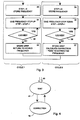
- Fig. 3 shows a flow chart for the operation cycles of Fig. 2, ie. operation in states 22 and 24.
- the receiver stores the current tuning frequency in memory and resets, ie. sets to 0, a certain STEP counter representing tuning steps.
- the receiver changes the tuning one step upward and increments the STEP counter value by one.
- the tuning of the receiver is carried out in steps, and the size of a step can be a fixed or a dynamically changing parameter.
- the size of a step is so small as compared to the reception frequency bandwidth in use that a tuning change of one or a few steps corresponds to finding the optimal tuning inside a frequency band and not to changing from a channel to another.
- step 32 the receiver examines whether the synchronizing element in the decoder stays locked to the clock frequency of the received signal after the tuning step.
- the receiver repeats the loop formed by steps 31 and 32 until locking is lost.
- the STEP counter value can have an upper limit, so that the receiver goes from step 32 to step 33 when the upper limit is reached even if locking were not lost.
- step 33 the receiver stores the STEP counter value that indicates how many tuning steps upward from the previous tuning frequency were needed until the locking was lost.
- the receiver restores the tuning to the frequency stored in step 30.
- the first operation cycle ends at step 33.
- the receiver sets the STEP counter value to zero and stores the current tuning frequency in memory in step 34.
- the loop formed by steps 35 and 36 corresponds to steps 31 and 32 of the first operation cycle, however in such a manner that the receiver changes the tuning step by step downwards, not upwards.
- the receiver notices in step 36 that the locking is lost, it goes to step 37 where it calculates the difference between the steps taken upward and downward before the locking was lost and selects a new tuning frequency which differs from the previous tuning frequency by half of the difference calculated. If, for example, it was taken seven steps up and five steps down before the locking was lost, the difference is two, and the receiver corrects the tuning frequency by one step up.
- the receiver rounds off the result to the nearest integer. It is obvious that the up and down directions in the embodiment shown in Fig. 3 are mutually exchangeable, so that the receiver takes tuning steps down in the first operation cycle, and up in the second operation cycle.
- the receiver corrects the tuning frequency only after every second active period.
- An embodiment is also possible that has no two separate operation cycles but the receiver carries out the whole series of operations needed for the tuning correction each time it has stopped receiving information.
- Fig. 4 shows a state diagram for such an embodiment.
- Arrow 40 corresponds to arrow 20 in Fig. 2, so operation according to the state diagram starts when a certain channel is found.
- state 41 the receiver is waiting for a suitable opportunity to start the tuning correction and in state 42 it corrects the tuning in the manner according to the invention.
- a first possibility is to examine according to the embodiment shown in Fig. 3, ie. first one direction (in Fig. 3, upward) until the locking is lost, and then the other direction.
- Fig. 5 shows an alternative embodiment of the method according to the state diagram shown in Fig. 4, wherein the receiver, in step 50, sets the STEP counter to zero, specifies the first direction (here, up), stores the current frequency in variable PF and stores the current tuning frequency in memory as variable TF.
- the receiver increments the STEP counter value by one, changes the sign of variable D representing the direction (absolute value of D is always 1), sets the value of variable PF to the current frequency and selects as a new frequency F a frequency that is a number of tuning steps away from the frequency indicated by variable PF, in the direction indicated by variable D, said number of tuning steps determined by the value of the STEP counter.
- the receiver examines whether the locking is lost.
- Steps 54 and 55 are mutually exclusive alternatives: the receiver selects a new tuning frequency which is one step away from the previously stored previous tuning frequency, but the direction depends on where, ie. on which side of the previous frequency, the locking was lost. If the locking was lost above the previous tuning frequency, the new tuning frequency is below the previous one. If the locking was lost below the previous tuning frequency, the new tuning frequency is above the previous one.
- the receiver extends the frequency band examined one step at a time, alternately in both directions from the original tuning frequency, until it encounters the closest frequency at which the locking is lost.
- this frequency can be called the critical frequency.
- the tuning frequency is corrected from the previous tuning frequency in the direction opposite to that of the critical frequency, ie. the frequency at which the locking was lost.
- the magnitude of the correction is advantageously one step, but it may also be greater. Assuming that the frequency band on which locking is possible has always a certain minimum width and the limit that causes the locking to be lost is encountered only one or two steps away from the old tuning frequency, the receiver can assume that the necessary correction in the opposite direction could be more than just one step.
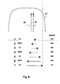
- Arrow 60 depicted by a thick broken line in Fig. 6 represents the original tuning frequency and curve 61 symbolizes the transmission of a certain IF filter as a function of frequency, showing that if the tuning approaches the edge of the transmission curve, the signal brought to the decoder is considerably weakened and the locking is lost.
- the method described in Figs. 5 and 6 shifts the frequency always by one step even if the original tuning frequency were right in the middle of the optimal range.
- a feature can be added in the method that restricts unnecessary tuning frequency changes. For example, if the locking is lost a distance away from the original tuning frequency, said distance being further than a certain threshold value, it can be deduced that the situation is almost optimal without any changes to the tuning frequency.
- the embodiment, in which the tuning correction is carried out in accordance with Figs. 4, 5 and 6 every time the receiver starts to examine frequencies other than the current tuning frequency, is disadvantageous in that after each reception period the reception part and the decoder must be on for longer than in the embodiment according to Figs. 2 and 3. This is not advantageous from the power consumption standpoint.
- the embodiment according to Figs. 4, 5 and 6 reacts to changes in the radio channel faster than the other embodiment and, therefore, it is probably the more suitable one of these two embodiments for a receiver which is not stationary.
- the receiver can also during operation change from the method according to the first alternative to the method according to the second alternative if it notices that changes are needed often and they are big. Similarly, the receiver can change from the second alternative to the first if it notices that changes are needed seldom and they are small.
- the method according to the invention does not make great hardware requirements of a radio receiver.
- a phase-locked loop or other arrangement for locking into a clock pulse already exists in most devices in which the invention can be applied.
- the arrangement is also capable of indicating whether locking is on or not.
- the tuning frequency of the radio device must be changeable in small steps.
- an embodiment can be disclosed wherein the tuning frequency is changed steplessly, but then the tuning frequency change has to be measured using an arrangement other than the counting of tuning steps described above.
- the tuning control block is usually a microprocessor, so the method according to the invention can be programmed into instructions that the processor will carry out along with other control operations.
- the processor receives as input the information about locking or non-locking and outputs the necessary commands concerning the change of tuning.
- the method according to the invention corrects tuning changes caused by changes in the characteristics of components due to aging or temperature variation. It improves the operation of a receiver also in a situation in which there is another signal at a frequency near the frequency of the desired signal. The decoder will lose locking more easily on that side of the desired frequency where the competing signal is, so the method according to the invention corrects the tuning away from the interfering signal.
Description
- The invention defined in the appended claims relates in general to the tuning of a radio receiver to a certain frequency and in particular to automatic tuning in order to ensure the best possible radio signal quality.
- Reception of a radio transmission suffers from spurious effects caused by the widening and shifting of the frequency band of the received signal, other radio transmissions at the same and adjacent frequencies and other electromagnetic radiation sources. In the receiver, the spurious effects are seen as noise and signal distortion. The problem is made more difficult by the fact that the spurious effects usually vary in time, especially in the case of mobile terminals. In addition to external spurious effects, also internal factors in the receiver, such as component aging, manufacturing tolerances, temperature drift, intermodulation frequencies, etc. affect the need for frequency tuning.
- It is known a prior art method called automatic frequency control (AFC), where the receiver includes a variable mixing frequency oscillator, a measurement circuit for measuring the received signal power, and a feedback loop which controls the oscillator so that mixing to the intermediate frequency is always performed using the mixing frequency that produces the highest received signal power. The disadvantage of this method is that the highest received signal power does not always correspond to the best signal quality e.g. in a situation where the receiver picks up an unwanted signal occurring at the same or nearly the same frequency as the desired signal. The tuned frequency is such that the attenuation of the intermediate frequency signal path is as low as possible. If the transmission curves of the filters are not symmetrical (the attenuation minimum at the middle of the pass band), the intermediate frequency will be detuned even if the receiver received nothing else than the desired signal. Tolerances of filters and their control circuits may cause considerable detuning so that the received signal becomes distorted and its quality deteriorates.
- Another known method is to use a frequency synthesizer, or an accurately tuned mixing oscillator which produces a mixing frequency that is a multiple of a fundamental frequency produced by a stable crystal oscillator. As the mixing frequency remains accurately the same, the receive filter can be made very narrowband so that the influence of spurious effects propagating at other frequences is reduced. The disadvantage of this method is that if the transmitter or receiver or a factor reflecting the radio signal on the path moves, the frequency of the desired signal will not remain constant but, instead, will change, which means that it may drift outside the narrow pass band of the filter. Furthermore, the tolerances of the filters and matching circuits may cause the signal path attenuation not be at its minimum at the nominal frequency. Then the signal-to-noise ratio will suffer, ie. the signal quality will get worse. The method is also susceptible to changes in component characteristics that occur in the course of time.
- A prior art method is called automatic gain control (AGC), where a signal coming to a receiver is attenuated in the pre-stages of the device if the received signal level is too high. In the AGC, the tuning of the receiver is not changed. For a double superheterodyne receiver, which has two intermediate frequencies, it is also known to detune the first mixing frequency obtained from the local oscillator so that the first intermediate frequency signal becomes offset. The second mixing frequency from the local oscillator is also detuned, however in such a manner that the second intermediate frequency signal moves, with respect to the nominal frequency, to the direction opposite to that of the first intermediate frequency signal. Then the effective bandwidth across the intermediate frequency stages becomes narrower. Narrowing and widening of the band may be based on the received signal level or on the signal-to-noise ratio. However, adjustment of the bandwidth and noise detection require separate components that increase manufacturing costs.
- A method is known from the Finnish patent application FI 962509, wherein a receiver decodes a digital signal and measures the frequency of occurrence of bit errors in the signal. The receiver tunes the oscillator frequency used in the down-conversion such that the bit error ratio (BER) is as low as possible. However, this method is relatively slow since the receiver examines several parallel frequencies and it has to demodulate and decode at each frequency a whole frame or other data structure so as to be able to determine, on the basis of the CRC (cyclic redundancy check) code or a corresponding part of said data structure, whether bit errors occurred in the signal on the transmission path.
- An object of this invention is to provide a method by means of which a receiver can automatically tune itself to the correct frequency in a quick and easily realizable manner. Another object of the invention is to provide a radio receiver which can apply the method according to the invention and which has no need for expensive special components.
- The objects of the invention are achieved by monitoring how the receiver stays locked to the clock pulse of the received signal and by tuning the receiver to the middle of the frequency band where locking is successful.
- The method according to the invention is characterized in that therein a current frequency is found by tuning the radio receiver in such a manner that the intermediate frequency is on the pass band of the receiver's IF filter, and the closest critical frequency at which the radio receiver loses synchronization to the clock frequency of the received signal is also found out, and the tuning frequency is corrected on the basis of the difference of the critical frequency found and the current frequency.
- The invention is also directed to a radio receiver which realizes the method according to the invention. The radio receiver according to the invention is characterized in that its control block comprises means for adjusting the tuning of the reception part in response to the information indicating whether locking is on.
- Ordinary modem radio receivers, such as paging devices or the reception parts of mobile telephones, for example, almost invariably include a part like a phase-locked loop with which the device can in the decoding stage lock itself to the clock frequency of the received signal and which produces some indication about whether the locking is on. The more accurately the receiver is tuned for the down-conversion and demodulation of the received signal, the more successfully the device can perform the locking. In the method according to the invention, tuning is attempted at both sides of a certain tuning frequency until the closest frequency is found at which the locking is lost, and, if necessary, a new tuning location is selected such that it is away from the frequency found. The frequency at which the locking is lost can be called the critical frequency.
- The term "clock frequency" must here be understood as having a broad meaning because it refers to all those substantially constant-frequency parts of the received signal on the basis of which the receiver can by a simple detection determine whether it is correctly synchronized to the received signal.
- The invention is described in more detail with reference to the preferred embodiments presented by way of example and to the attached drawing, wherein
- Fig. 1
- shows a block diagram of a radio receiver that can apply the method according to the invention,
- Fig. 2
- shows a simple state diagram of a first preferred embodiment of the method according to the invention,
- Fig. 3
- shows a flow chart of the first preferred embodiment of the method according to the invention,
- Fig. 4
- shows a simple state diagram of a second preferred embodiment of the method according to the invention,
- Fig. 5
- shows a flow chart of the second preferred embodiment of the method according to the invention, and
- Fig. 6
- shows symbolically the method according to the invention in a case.
- Fig. 1 shows a
radio receiver 10 which comprises, among other things, a reception, down-conversion and demodulation part H (which will be hereinafter called a reception part in short), a decodingpart 12 and areceiver control block 13. Aradio signal 14 arrives in thereception part 11, and a demodulatedsignal 15 is sent from the reception part to thedecoding part 12. The decoding part directs the decodedsignal 16 to thecontrol block 13 and also indicates whether it is locked to the clock frequency of the received signal. "Locking" means that the phase-lockedloop 19 in thedecoding part 12 or other known synchronizing element indicates that the clock in the decoding part and the clock frequency signal in the received signal are synchronized. The indication about the locking or absence of locking is denoted byreference designator 17 in Fig. 1.Reference designator 18 represents the commands issued by thecontrol block 13 to thereception part 11 in order to change the tuning frequency or frequencies. The command link betweenblocks reception part 11 sends information to thecontrol block 13 regarding the frequency in use and other relevant matters. - The method according to the invention can be advantageously applied in selective call receivers and other portable radio devices where, as is known, low power consumption is a very significant factor affecting practicability. So, it is desirable that the application of the method according to the invention to the radio apparatus according to Fig. 1 will not significantly increase the power consumption of the apparatus. Selective call receivers and other portable radio devices are often characterized in that a particular device receives information only at times, so that during other times the device is in passive state where it uses the minimum amount of electric power. On the other hand, when the device is receiving information, its decoder must be continuously locked to the clock frequency of the received signal, so that during reception the tuning cannot be changed using the method of finding the location where the synchronization is lost. In the preferred embodiment, the receiver applying the invention makes the tuning correction according to the invention immediately after it has stopped receiving the information coming to it. After the tuning correction the receiver can enter the passive state.
- Fig. 2 shows a state diagram of an advantageous embodiment of the method according to the invention, in which the tuning correction is divided into two successive operation cycles. Operation starts at the location depicted by arrow 20, as the receiver finds a desired reception channel by means of a known procedure. The receiver is tuned to a certain "current tuning frequency" when the intermediate frequency, to which the signal is mixed in reception, is on the pass band of the receiver's IF filter. In
state 21 the receiver is waiting for a suitable opportunity to start the tuning correction. Above it was stated that a suitable opportunity is the end of a particular reception period, for example, whereby the receiver goes intostate 22 representing the first operation cycle. Then comes a new wait period instate 23, and as the next suitable opportunity arises the receiver goes intostate 24 representing the second operation cycle, whereafter the operation starts over from the beginning,state 21. - Fig. 3 shows a flow chart for the operation cycles of Fig. 2, ie. operation in
states step 30, the receiver stores the current tuning frequency in memory and resets, ie. sets to 0, a certain STEP counter representing tuning steps. In thenext step 31, the receiver changes the tuning one step upward and increments the STEP counter value by one. Here it is assumed that the tuning of the receiver is carried out in steps, and the size of a step can be a fixed or a dynamically changing parameter. However, the size of a step is so small as compared to the reception frequency bandwidth in use that a tuning change of one or a few steps corresponds to finding the optimal tuning inside a frequency band and not to changing from a channel to another. Instep 32 the receiver examines whether the synchronizing element in the decoder stays locked to the clock frequency of the received signal after the tuning step. The receiver repeats the loop formed bysteps step 32 to step 33 when the upper limit is reached even if locking were not lost. Instep 33 the receiver stores the STEP counter value that indicates how many tuning steps upward from the previous tuning frequency were needed until the locking was lost. In addition, the receiver restores the tuning to the frequency stored instep 30. - The first operation cycle ends at
step 33. At the beginning of the second operation cycle the receiver sets the STEP counter value to zero and stores the current tuning frequency in memory instep 34. The loop formed bysteps steps step 36 that the locking is lost, it goes to step 37 where it calculates the difference between the steps taken upward and downward before the locking was lost and selects a new tuning frequency which differs from the previous tuning frequency by half of the difference calculated. If, for example, it was taken seven steps up and five steps down before the locking was lost, the difference is two, and the receiver corrects the tuning frequency by one step up. If the difference of the steps up and down is an odd number, which does not yield an integer when halved, the receiver rounds off the result to the nearest integer. It is obvious that the up and down directions in the embodiment shown in Fig. 3 are mutually exchangeable, so that the receiver takes tuning steps down in the first operation cycle, and up in the second operation cycle. - In the embodiment described above, the receiver corrects the tuning frequency only after every second active period. An embodiment is also possible that has no two separate operation cycles but the receiver carries out the whole series of operations needed for the tuning correction each time it has stopped receiving information. Fig. 4 shows a state diagram for such an embodiment.
Arrow 40 corresponds to arrow 20 in Fig. 2, so operation according to the state diagram starts when a certain channel is found. Instate 41, the receiver is waiting for a suitable opportunity to start the tuning correction and instate 42 it corrects the tuning in the manner according to the invention. A first possibility is to examine according to the embodiment shown in Fig. 3, ie. first one direction (in Fig. 3, upward) until the locking is lost, and then the other direction. - Fig. 5 shows an alternative embodiment of the method according to the state diagram shown in Fig. 4, wherein the receiver, in
step 50, sets the STEP counter to zero, specifies the first direction (here, up), stores the current frequency in variable PF and stores the current tuning frequency in memory as variable TF. Instep 51, the receiver increments the STEP counter value by one, changes the sign of variable D representing the direction (absolute value of D is always 1), sets the value of variable PF to the current frequency and selects as a new frequency F a frequency that is a number of tuning steps away from the frequency indicated by variable PF, in the direction indicated by variable D, said number of tuning steps determined by the value of the STEP counter. Instep 52, the receiver examines whether the locking is lost. As long as the locking is not lost, the receiver executes the loop formed ofstates step 53, which was the last stepping direction.Steps - The embodiment of the invention shown in Fig. 5 can be described as follows: the receiver extends the frequency band examined one step at a time, alternately in both directions from the original tuning frequency, until it encounters the closest frequency at which the locking is lost. As above, this frequency can be called the critical frequency. Then the tuning frequency is corrected from the previous tuning frequency in the direction opposite to that of the critical frequency, ie. the frequency at which the locking was lost. The magnitude of the correction is advantageously one step, but it may also be greater. Assuming that the frequency band on which locking is possible has always a certain minimum width and the limit that causes the locking to be lost is encountered only one or two steps away from the old tuning frequency, the receiver can assume that the necessary correction in the opposite direction could be more than just one step.
-
Arrow 60 depicted by a thick broken line in Fig. 6 represents the original tuning frequency andcurve 61 symbolizes the transmission of a certain IF filter as a function of frequency, showing that if the tuning approaches the edge of the transmission curve, the signal brought to the decoder is considerably weakened and the locking is lost. The horizontal arrows depict, from top down, the extending of the frequency band examined as follows: first the receiver examines the frequency which is one step above (here, to the right), then the frequency which is one step below the original tuning frequency and so on until the seventh step transition upwards ends up so close to the transmission curve edge that the locking is lost. As a consequence, the receiver selects the frequency depicted by thethin arrow 62 as the new tuning frequency which is one step below theoriginal tuning frequency 60. - The method described in Figs. 5 and 6 shifts the frequency always by one step even if the original tuning frequency were right in the middle of the optimal range. To prevent this, a feature can be added in the method that restricts unnecessary tuning frequency changes. For example, if the locking is lost a distance away from the original tuning frequency, said distance being further than a certain threshold value, it can be deduced that the situation is almost optimal without any changes to the tuning frequency. In an embodiment of the invention, it is possible to examine, after the locking is lost on one side of the current frequency, how far away on the other side of the current frequency the locking will be lost. If a critical frequency is found at the same distance on both sides of the current frequency, the tuning need not be corrected.
- The embodiment, in which the tuning correction is carried out in accordance with Figs. 4, 5 and 6 every time the receiver starts to examine frequencies other than the current tuning frequency, is disadvantageous in that after each reception period the reception part and the decoder must be on for longer than in the embodiment according to Figs. 2 and 3. This is not advantageous from the power consumption standpoint. However, the embodiment according to Figs. 4, 5 and 6 reacts to changes in the radio channel faster than the other embodiment and, therefore, it is probably the more suitable one of these two embodiments for a receiver which is not stationary. The receiver can also during operation change from the method according to the first alternative to the method according to the second alternative if it notices that changes are needed often and they are big. Similarly, the receiver can change from the second alternative to the first if it notices that changes are needed seldom and they are small.
- The method according to the invention does not make great hardware requirements of a radio receiver. A phase-locked loop or other arrangement for locking into a clock pulse already exists in most devices in which the invention can be applied. The arrangement is also capable of indicating whether locking is on or not. According to the invention, the tuning frequency of the radio device must be changeable in small steps. Of course, an embodiment can be disclosed wherein the tuning frequency is changed steplessly, but then the tuning frequency change has to be measured using an arrangement other than the counting of tuning steps described above. In a modem radio device the tuning control block is usually a microprocessor, so the method according to the invention can be programmed into instructions that the processor will carry out along with other control operations. The processor receives as input the information about locking or non-locking and outputs the necessary commands concerning the change of tuning.
- The method according to the invention corrects tuning changes caused by changes in the characteristics of components due to aging or temperature variation. It improves the operation of a receiver also in a situation in which there is another signal at a frequency near the frequency of the desired signal. The decoder will lose locking more easily on that side of the desired frequency where the competing signal is, so the method according to the invention corrects the tuning away from the interfering signal.
Claims (12)
- A method for tuning a radio receiver (10) to an optimal tuning frequency (62), characterized in that therein it is determined a current tuning frequency (60) by tuning the radio receiver in such a manner that the intermediate frequency is on the pass band of the receiver's intermediate frequency filter, and it is also determined the closest critical frequency at which the radio receiver loses the locking to the clock frequency of the received signal (14, 15), and the tuning frequency is corrected according to the difference of the critical frequency found and the current frequency.
- The method of claim 1, characterized in that therein the radio receiver is tuned by changing the mixing frequency used in the down-conversion (11) of the radio signal.
- The method of claim 1, characterized in that when the critical frequency is found, the tuning frequency is corrected from the current frequency in a direction other than where said critical frequency is located.
- The method of claim 3, characterized in that it comprises stages, whereinthe tuning is changed (31) from the current tuning frequency in a first direction until the radio receiver loses (32) the locking to the clock frequency of the received signal, and the magnitude of the required first tuning change is measured (33),the tuning is changed (35) from the current tuning frequency in a second direction until the radio receiver loses (36) the locking to the clock frequency of the received signal, and the magnitude of the required second tuning change is measured (37),the direction in which the measured magnitude of the tuning change is greater is selected as the direction of tuning correction, andthe tuning is corrected from the current tuning frequency in the selected direction by an amount which is ½ of the absolute value of the difference of the first and the second tuning change.
- The method of claim 4, characterized in that the change and correction of tuning are carried out in steps of predetermined magnitude.
- The method of claim 3, characterized in that it comprises stages, whereinit is started (50) from the current tuning frequency,the tuning frequency area examined is extended from the current tuning frequency by a predetermined first step alternately in both directions (51) until it is found (52) a critical frequency at which the radio receiver loses the locking to the clock frequency of the received signal,a direction is chosen (53) for the tuning correction which is in the opposite direction from the current tuning frequency than the critical frequency found, andthe tuning is corrected (54, 55) by a predetermined second step in the direction chosen.
- The method of claim 6, characterized in that said second step is equal to said first step.
- The method of claim 1, characterized in that the search for the critical frequency is carried out in the radio receiver immediately after the radio receiver has stopped receiving information coming to it.
- The method of claim 1, characterized in that if the difference of the critical frequency found and the current tuning frequency is greater than a certain threshold value, the tuning will not be corrected.
- A radio receiver (10) comprising a reception part (11) with adjustable tuning, a control block (13), and a decoding part (12) connected to these, said decoding part further comprising means (19) for locking to a clock frequency in a received signal and means for sending information (17) to the control block about whether the locking is on, characterized in that the control block (13) comprises means for adjusting (18) the tuning of the reception part in response to the information indicating whether the locking is on.
- The radio receiver of claim 10, characterized in that said means for locking to a clock frequency in the received signal comprises a phase-locked loop (19).
- The radio receiver of claim 10, characterized in that it is a selective call receiver.
Applications Claiming Priority (2)
| Application Number | Priority Date | Filing Date | Title |
|---|---|---|---|
| FI964442A FI102229B (en) | 1996-11-05 | 1996-11-05 | Method of improving tuner tuning of radio receiver and radio receiver |
| FI964442 | 1996-11-05 |
Publications (2)
| Publication Number | Publication Date |
|---|---|
| EP0840447A1 EP0840447A1 (en) | 1998-05-06 |
| EP0840447B1 true EP0840447B1 (en) | 2004-03-17 |
Family
ID=8547007
Family Applications (1)
| Application Number | Title | Priority Date | Filing Date |
|---|---|---|---|
| EP97660116A Expired - Lifetime EP0840447B1 (en) | 1996-11-05 | 1997-11-04 | Method for improving the tuning of a radio receiver and a radio receiver |
Country Status (4)
| Country | Link |
|---|---|
| US (1) | US6125267A (en) |
| EP (1) | EP0840447B1 (en) |
| DE (1) | DE69728109T2 (en) |
| FI (1) | FI102229B (en) |
Families Citing this family (7)
| Publication number | Priority date | Publication date | Assignee | Title |
|---|---|---|---|---|
| JPH11215111A (en) * | 1998-01-26 | 1999-08-06 | Mitsubishi Electric Corp | Radio terminal equipment |
| US6603751B1 (en) * | 1998-02-13 | 2003-08-05 | Qualcomm Incorporated | Method and system for performing a handoff in a wireless communication system, such as a hard handoff |
| US6587446B2 (en) * | 1999-02-11 | 2003-07-01 | Qualcomm Incorporated | Handoff in a wireless communication system |
| DE60037722T2 (en) * | 2000-05-17 | 2009-01-15 | Sony Deutschland Gmbh | AM receiver |
| US6912378B2 (en) * | 2001-05-15 | 2005-06-28 | Raddscann Corporation | Multiple band scanning receiver system having data and speech searching capability |
| US7030711B2 (en) * | 2004-02-10 | 2006-04-18 | Agilent Technologies, Inc. | Centering a multi-band voltage controlled oscillator |
| US8964692B2 (en) * | 2008-11-10 | 2015-02-24 | Qualcomm Incorporated | Spectrum sensing of bluetooth using a sequence of energy detection measurements |
Family Cites Families (7)
| Publication number | Priority date | Publication date | Assignee | Title |
|---|---|---|---|---|
| US4151463A (en) * | 1978-02-02 | 1979-04-24 | Bell Telephone Laboratories, Incorporated | Phase locked loop indicator |
| JPH01196946A (en) * | 1988-02-01 | 1989-08-08 | Toshiba Corp | Frequency controller |
| JPH06188763A (en) * | 1992-08-18 | 1994-07-08 | Philips Electron Nv | Detector and receiver for high-frequency signal using it |
| FI94689C (en) * | 1992-12-10 | 1995-10-10 | Nokia Mobile Phones Ltd | Reconciliation of tuning circuits in a radio receiver |
| MA23383A1 (en) * | 1993-12-03 | 1995-07-01 | Scientific Atlanta | METHOD AND DEVICE FOR LOCATING AND TRACKING A QPSK CARRIER |
| US5457815A (en) * | 1994-01-13 | 1995-10-10 | Morewitz, Ii; Herbert | RBDS scan, identify and select receiving method and system |
| EP0987820A3 (en) * | 1995-10-13 | 2002-11-20 | Pioneer Electronic Corporation | Receiver and frequency synthesizer tuner |
-
1996
- 1996-11-05 FI FI964442A patent/FI102229B/en active
-
1997
- 1997-11-04 EP EP97660116A patent/EP0840447B1/en not_active Expired - Lifetime
- 1997-11-04 US US08/963,811 patent/US6125267A/en not_active Expired - Lifetime
- 1997-11-04 DE DE69728109T patent/DE69728109T2/en not_active Expired - Lifetime
Also Published As
| Publication number | Publication date |
|---|---|
| FI102229B1 (en) | 1998-10-30 |
| FI964442A0 (en) | 1996-11-05 |
| FI964442A (en) | 1998-05-06 |
| EP0840447A1 (en) | 1998-05-06 |
| FI102229B (en) | 1998-10-30 |
| US6125267A (en) | 2000-09-26 |
| DE69728109D1 (en) | 2004-04-22 |
| DE69728109T2 (en) | 2005-01-20 |
Similar Documents
| Publication | Publication Date | Title |
|---|---|---|
| KR960008948B1 (en) | Radio receiver | |
| US5222255A (en) | Intermodulation controller for radio receiver | |
| JP2515681B2 (en) | Receiver with automatic frequency control | |
| US6744828B1 (en) | Receiving apparatus | |
| EP0475705A2 (en) | RF filter alignment using digital processor clock | |
| EP0545342B1 (en) | Method of calibrating a superheterodyne receiver | |
| US6480555B1 (en) | Method and apparatus for extended range frequency correction burst detection | |
| US7509106B2 (en) | Test signal generation circuit, and reception circuit | |
| KR100325771B1 (en) | Automatic frequency tracking device of television signal receiving system and method | |
| EP0840447B1 (en) | Method for improving the tuning of a radio receiver and a radio receiver | |
| US5335354A (en) | Demodulation circuit having automatic frequency control function | |
| US6229991B1 (en) | Method of and apparatus for automatic frequency control range extension | |
| EP0919084B1 (en) | Digital communication device | |
| EP1150426B1 (en) | Synthesizer receiver | |
| EP0833448B1 (en) | Frequency adjusting method for use with digital receiver and frequency adjusting circuit thereof | |
| US7945218B1 (en) | Method and system for tuning quality factor in high-Q, high-frequency filters | |
| US5940747A (en) | Apparatus and method of acquiring a carrier signal in a wireless receiver | |
| EP1156589B1 (en) | AM receiver | |
| US5949472A (en) | Method and apparatus for tuning channels for CATV and television applications | |
| US6370367B1 (en) | Method for improving the quality of reception in a radio receiver and a radio receiver | |
| US6064270A (en) | System and method for compensating for reference frequency drift in a communications system | |
| EP0948134A2 (en) | Radio receiver | |
| EP0871289B1 (en) | Automatic frequency control system and method using multiple threshold levels | |
| KR0162437B1 (en) | Frequency a.f.t device & method of digital satellite broadcasting receiver | |
| JP2019009497A (en) | Semiconductor device and method thereof |
Legal Events
| Date | Code | Title | Description |
|---|---|---|---|
| PUAI | Public reference made under article 153(3) epc to a published international application that has entered the european phase |
Free format text: ORIGINAL CODE: 0009012 |
|
| AK | Designated contracting states |
Kind code of ref document: A1 Designated state(s): DE FR GB SE |
|
| AX | Request for extension of the european patent |
Free format text: AL;LT;LV;MK;RO;SI |
|
| 17P | Request for examination filed |
Effective date: 19980810 |
|
| AKX | Designation fees paid |
Free format text: DE FR GB SE |
|
| RBV | Designated contracting states (corrected) |
Designated state(s): DE FR GB SE |
|
| RAP1 | Party data changed (applicant data changed or rights of an application transferred) |
Owner name: NOKIA CORPORATION |
|
| GRAP | Despatch of communication of intention to grant a patent |
Free format text: ORIGINAL CODE: EPIDOSNIGR1 |
|
| GRAS | Grant fee paid |
Free format text: ORIGINAL CODE: EPIDOSNIGR3 |
|
| GRAA | (expected) grant |
Free format text: ORIGINAL CODE: 0009210 |
|
| AK | Designated contracting states |
Kind code of ref document: B1 Designated state(s): DE FR GB SE |
|
| REG | Reference to a national code |
Ref country code: GB Ref legal event code: FG4D |
|
| REF | Corresponds to: |
Ref document number: 69728109 Country of ref document: DE Date of ref document: 20040422 Kind code of ref document: P |
|
| REG | Reference to a national code |
Ref country code: SE Ref legal event code: TRGR |
|
| ET | Fr: translation filed | ||
| PLBE | No opposition filed within time limit |
Free format text: ORIGINAL CODE: 0009261 |
|
| STAA | Information on the status of an ep patent application or granted ep patent |
Free format text: STATUS: NO OPPOSITION FILED WITHIN TIME LIMIT |
|
| 26N | No opposition filed |
Effective date: 20041220 |
|
| PGFP | Annual fee paid to national office [announced via postgrant information from national office to epo] |
Ref country code: FR Payment date: 20101123 Year of fee payment: 14 |
|
| PGFP | Annual fee paid to national office [announced via postgrant information from national office to epo] |
Ref country code: SE Payment date: 20101111 Year of fee payment: 14 Ref country code: GB Payment date: 20101103 Year of fee payment: 14 |
|
| REG | Reference to a national code |
Ref country code: SE Ref legal event code: EUG |
|
| GBPC | Gb: european patent ceased through non-payment of renewal fee |
Effective date: 20111104 |
|
| REG | Reference to a national code |
Ref country code: FR Ref legal event code: ST Effective date: 20120731 |
|
| PG25 | Lapsed in a contracting state [announced via postgrant information from national office to epo] |
Ref country code: GB Free format text: LAPSE BECAUSE OF NON-PAYMENT OF DUE FEES Effective date: 20111104 Ref country code: SE Free format text: LAPSE BECAUSE OF NON-PAYMENT OF DUE FEES Effective date: 20111105 |
|
| PG25 | Lapsed in a contracting state [announced via postgrant information from national office to epo] |
Ref country code: FR Free format text: LAPSE BECAUSE OF NON-PAYMENT OF DUE FEES Effective date: 20111130 |
|
| PGFP | Annual fee paid to national office [announced via postgrant information from national office to epo] |
Ref country code: DE Payment date: 20121031 Year of fee payment: 16 |
|
| REG | Reference to a national code |
Ref country code: DE Ref legal event code: R119 Ref document number: 69728109 Country of ref document: DE Effective date: 20140603 |
|
| PG25 | Lapsed in a contracting state [announced via postgrant information from national office to epo] |
Ref country code: DE Free format text: LAPSE BECAUSE OF NON-PAYMENT OF DUE FEES Effective date: 20140603 |