EP0840407A2 - Elektrischer Verbinder zwischen einem Leiterplattenpaar - Google Patents
Elektrischer Verbinder zwischen einem Leiterplattenpaar Download PDFInfo
- Publication number
- EP0840407A2 EP0840407A2 EP97118832A EP97118832A EP0840407A2 EP 0840407 A2 EP0840407 A2 EP 0840407A2 EP 97118832 A EP97118832 A EP 97118832A EP 97118832 A EP97118832 A EP 97118832A EP 0840407 A2 EP0840407 A2 EP 0840407A2
- Authority
- EP
- European Patent Office
- Prior art keywords
- printed circuit
- electrical
- contact points
- contacts
- right angle
- Prior art date
- Legal status (The legal status is an assumption and is not a legal conclusion. Google has not performed a legal analysis and makes no representation as to the accuracy of the status listed.)
- Granted
Links
- 239000000463 material Substances 0.000 claims description 6
- 230000013011 mating Effects 0.000 claims description 3
- 229910000679 solder Inorganic materials 0.000 abstract description 3
- RYGMFSIKBFXOCR-UHFFFAOYSA-N Copper Chemical compound [Cu] RYGMFSIKBFXOCR-UHFFFAOYSA-N 0.000 description 2
- PXHVJJICTQNCMI-UHFFFAOYSA-N Nickel Chemical compound [Ni] PXHVJJICTQNCMI-UHFFFAOYSA-N 0.000 description 2
- 238000010276 construction Methods 0.000 description 2
- 229910052802 copper Inorganic materials 0.000 description 2
- 239000010949 copper Substances 0.000 description 2
- 238000005476 soldering Methods 0.000 description 2
- 239000003990 capacitor Substances 0.000 description 1
- 239000011248 coating agent Substances 0.000 description 1
- 238000000576 coating method Methods 0.000 description 1
- 239000004020 conductor Substances 0.000 description 1
- 230000002950 deficient Effects 0.000 description 1
- 230000008030 elimination Effects 0.000 description 1
- 238000003379 elimination reaction Methods 0.000 description 1
- 238000009434 installation Methods 0.000 description 1
- 238000004519 manufacturing process Methods 0.000 description 1
- 229910052759 nickel Inorganic materials 0.000 description 1
- 239000011800 void material Substances 0.000 description 1
Images

Classifications
-
- H—ELECTRICITY
- H01—ELECTRIC ELEMENTS
- H01R—ELECTRICALLY-CONDUCTIVE CONNECTIONS; STRUCTURAL ASSOCIATIONS OF A PLURALITY OF MUTUALLY-INSULATED ELECTRICAL CONNECTING ELEMENTS; COUPLING DEVICES; CURRENT COLLECTORS
- H01R12/00—Structural associations of a plurality of mutually-insulated electrical connecting elements, specially adapted for printed circuits, e.g. printed circuit boards [PCB], flat or ribbon cables, or like generally planar structures, e.g. terminal strips, terminal blocks; Coupling devices specially adapted for printed circuits, flat or ribbon cables, or like generally planar structures; Terminals specially adapted for contact with, or insertion into, printed circuits, flat or ribbon cables, or like generally planar structures
- H01R12/70—Coupling devices
- H01R12/7005—Guiding, mounting, polarizing or locking means; Extractors
- H01R12/7011—Locking or fixing a connector to a PCB
- H01R12/7035—Locking or fixing a connector to a PCB involving non-elastic deformation, e.g. plastic deformation, melting
-
- H—ELECTRICITY
- H01—ELECTRIC ELEMENTS
- H01R—ELECTRICALLY-CONDUCTIVE CONNECTIONS; STRUCTURAL ASSOCIATIONS OF A PLURALITY OF MUTUALLY-INSULATED ELECTRICAL CONNECTING ELEMENTS; COUPLING DEVICES; CURRENT COLLECTORS
- H01R12/00—Structural associations of a plurality of mutually-insulated electrical connecting elements, specially adapted for printed circuits, e.g. printed circuit boards [PCB], flat or ribbon cables, or like generally planar structures, e.g. terminal strips, terminal blocks; Coupling devices specially adapted for printed circuits, flat or ribbon cables, or like generally planar structures; Terminals specially adapted for contact with, or insertion into, printed circuits, flat or ribbon cables, or like generally planar structures
- H01R12/70—Coupling devices
- H01R12/71—Coupling devices for rigid printing circuits or like structures
- H01R12/72—Coupling devices for rigid printing circuits or like structures coupling with the edge of the rigid printed circuits or like structures
- H01R12/722—Coupling devices for rigid printing circuits or like structures coupling with the edge of the rigid printed circuits or like structures coupling devices mounted on the edge of the printed circuits
- H01R12/727—Coupling devices presenting arrays of contacts
-
- H—ELECTRICITY
- H01—ELECTRIC ELEMENTS
- H01R—ELECTRICALLY-CONDUCTIVE CONNECTIONS; STRUCTURAL ASSOCIATIONS OF A PLURALITY OF MUTUALLY-INSULATED ELECTRICAL CONNECTING ELEMENTS; COUPLING DEVICES; CURRENT COLLECTORS
- H01R13/00—Details of coupling devices of the kinds covered by groups H01R12/70 or H01R24/00 - H01R33/00
- H01R13/648—Protective earth or shield arrangements on coupling devices, e.g. anti-static shielding
- H01R13/658—High frequency shielding arrangements, e.g. against EMI [Electro-Magnetic Interference] or EMP [Electro-Magnetic Pulse]
- H01R13/6598—Shield material
- H01R13/6599—Dielectric material made conductive, e.g. plastic material coated with metal
-
- Y—GENERAL TAGGING OF NEW TECHNOLOGICAL DEVELOPMENTS; GENERAL TAGGING OF CROSS-SECTIONAL TECHNOLOGIES SPANNING OVER SEVERAL SECTIONS OF THE IPC; TECHNICAL SUBJECTS COVERED BY FORMER USPC CROSS-REFERENCE ART COLLECTIONS [XRACs] AND DIGESTS
- Y10—TECHNICAL SUBJECTS COVERED BY FORMER USPC
- Y10S—TECHNICAL SUBJECTS COVERED BY FORMER USPC CROSS-REFERENCE ART COLLECTIONS [XRACs] AND DIGESTS
- Y10S439/00—Electrical connectors
- Y10S439/931—Conductive coating
Definitions
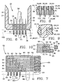
- the subject invention is an electrical connector formed of a vertical pin header and a right angle receptacle with the vertical pin header including a plurality of first contacts and the right angle receptacle including a plurality of second contacts.
- the center-to-center distance between each of the first contacts and between each of the second contacts is to be about two millimeters.
- Each of the first contacts are to be mounted within an appropriate receiving hole formed within a first printed circuit board with there being a separate hole for each first contact.
- Each of the second contacts are also mounted within an appropriate receiving hole formed within a second printed circuit board with there being a separate hole for each second contact.
- Each of the second contacts is elongated in the shape of a right angle.
- Each second contact is electrically connected with a first contact with the right angle receptacle matingly connecting with the vertical pin header.
- the right angle receptacle includes at least one deformable peg which is conducted through a mating opening formed within the printed circuit board on which it is mounted.
- the tip of the deformable peg extends outward from the back wall of the printed circuit board with the right angle receptacle being mounted on the front wall of the printed circuit board.
- the tip of the deformable peg is to be manually deformed (squashed) securely mounting the right angle receptacle onto the printed circuit board.
- the entire exterior surface of the vertical pin header and the right angle receptacle is coated with an electrically conductive layer.
- each of the positive contacts that protrude from the header Surrounding each of the positive contacts that protrude from the header is a plurality of electrical contact points with these electrical contact points to connect with the electrically grounding layer.
- a similar series of electrical contact points surround each electrical contact protruding from the right angle receptacle.
- the electrical contacts of both the header and the right angle receptacle are each to be electrically connected to separate printed circuit boards.
- the right angle receptacle is to be matingly connected to the vertical pin header with the electrical grounding layers of both the vertical pin header and the right angle receptacle to be in contact with each other thereby electrically conductive there between.
Landscapes
- Coupling Device And Connection With Printed Circuit (AREA)
Applications Claiming Priority (2)
| Application Number | Priority Date | Filing Date | Title |
|---|---|---|---|
| US08/741,048 US5718606A (en) | 1996-10-30 | 1996-10-30 | Electrical connector between a pair of printed circuit boards |
| US741048 | 1996-10-30 |
Publications (3)
| Publication Number | Publication Date |
|---|---|
| EP0840407A2 true EP0840407A2 (de) | 1998-05-06 |
| EP0840407A3 EP0840407A3 (de) | 1998-11-11 |
| EP0840407B1 EP0840407B1 (de) | 2005-09-07 |
Family
ID=24979153
Family Applications (1)
| Application Number | Title | Priority Date | Filing Date |
|---|---|---|---|
| EP97118832A Expired - Lifetime EP0840407B1 (de) | 1996-10-30 | 1997-10-29 | Elektrischer Verbinder zwischen einem Leiterplattenpaar |
Country Status (3)
| Country | Link |
|---|---|
| US (1) | US5718606A (de) |
| EP (1) | EP0840407B1 (de) |
| DE (1) | DE69734136D1 (de) |
Families Citing this family (45)
| Publication number | Priority date | Publication date | Assignee | Title |
|---|---|---|---|---|
| JP2000516385A (ja) | 1996-08-20 | 2000-12-05 | バーグ・テクノロジー・インコーポレーテッド | 高速モジュラー電気コネクタ及びこれに使用されるレセプタクル |
| EP1005706B1 (de) * | 1997-08-20 | 2002-11-13 | Berg Electronics Manufacturing B.V. | Elektrischer,modularer verbinder für hohe übertragungsgeschwindigkeiten und dazugehöriges aufnahmeteil |
| US6494734B1 (en) * | 1997-09-30 | 2002-12-17 | Fci Americas Technology, Inc. | High density electrical connector assembly |
| WO1999036998A1 (en) * | 1998-01-16 | 1999-07-22 | Berg Technology, Inc. | Shield accessory plate for plug |
| FR2780560B1 (fr) * | 1998-06-30 | 2003-10-03 | Framatome Connectors Int | Connecteur pour signaux a haute frequence |
| TW406874U (en) * | 1998-07-14 | 2000-09-21 | Hon Hai Prec Ind Co Ltd | Receptacle connector |
| US6305947B1 (en) | 1998-11-19 | 2001-10-23 | Berg Technology, Inc. | Angled coaxial connector module |
| US6181219B1 (en) * | 1998-12-02 | 2001-01-30 | Teradyne, Inc. | Printed circuit board and method for fabricating such board |
| US6390851B1 (en) | 1999-10-16 | 2002-05-21 | Berg Technology, Inc. | Electrical connector with internal shield |
| US6325672B1 (en) | 1999-10-16 | 2001-12-04 | Berg Technology, Inc. | Electrical connector with internal shield and filter |
| US6375506B1 (en) | 1999-10-19 | 2002-04-23 | Tyco Electronics Logistics A.G. | High-density high-speed input/output connector |
| US7018239B2 (en) * | 2001-01-22 | 2006-03-28 | Molex Incorporated | Shielded electrical connector |
| GB2371261B (en) * | 2001-01-22 | 2004-04-07 | Itt Mfg Enterprises Inc | Electrical component with conductive tracks |
| US6592382B2 (en) | 2001-12-17 | 2003-07-15 | Woody Wurster | Simplified board connector |
| CN100380747C (zh) * | 2002-05-06 | 2008-04-09 | 莫莱克斯公司 | 用于差分信号连接器的端子组件 |
| US6905367B2 (en) | 2002-07-16 | 2005-06-14 | Silicon Bandwidth, Inc. | Modular coaxial electrical interconnect system having a modular frame and electrically shielded signal paths and a method of making the same |
| US7344388B2 (en) * | 2005-11-24 | 2008-03-18 | Hirschmann Automotive Gmbh | Press-in contact with crimp arms for a circuit board |
| US7160151B1 (en) | 2005-12-14 | 2007-01-09 | Component Equipment Company, Inc. | Electrical connector system |
| US7201587B1 (en) * | 2006-07-31 | 2007-04-10 | Delphi Technologies, Inc. | Electrical connector with right angle terminal pins |
| US7999192B2 (en) | 2007-03-14 | 2011-08-16 | Amphenol Corporation | Adjacent plated through holes with staggered couplings for crosstalk reduction in high speed printed circuit boards |
| US7766696B2 (en) * | 2007-07-26 | 2010-08-03 | Tyco Electronics Corporation | Coaxial cable connector assembly |
| US8366485B2 (en) * | 2009-03-19 | 2013-02-05 | Fci Americas Technology Llc | Electrical connector having ribbed ground plate |
| US8231415B2 (en) | 2009-07-10 | 2012-07-31 | Fci Americas Technology Llc | High speed backplane connector with impedance modification and skew correction |
| US8784132B2 (en) * | 2010-11-18 | 2014-07-22 | Tyco Electronics Corporation | Electrical connector assembly having connector shroud |
| US8808010B2 (en) * | 2011-06-06 | 2014-08-19 | Interconnect Devices, Inc. | Insulated metal socket |
| DE102011052792B4 (de) * | 2011-08-18 | 2014-05-22 | HARTING Electronics GmbH | Isolierkörper mit Schirmkreuz |
| EP2624034A1 (de) | 2012-01-31 | 2013-08-07 | Fci | Abbaubare optische Kupplungsvorrichtung |
| US8662932B2 (en) * | 2012-02-10 | 2014-03-04 | Tyco Electronics Corporation | Connector system using right angle, board-mounted connectors |
| CN103296537B (zh) * | 2012-02-22 | 2015-10-07 | 富士康(昆山)电脑接插件有限公司 | 电连接器及电连接器组件 |
| CN103296510B (zh) | 2012-02-22 | 2015-11-25 | 富士康(昆山)电脑接插件有限公司 | 端子模组及端子模组的制造方法 |
| US8944831B2 (en) | 2012-04-13 | 2015-02-03 | Fci Americas Technology Llc | Electrical connector having ribbed ground plate with engagement members |
| USD727268S1 (en) | 2012-04-13 | 2015-04-21 | Fci Americas Technology Llc | Vertical electrical connector |
| US9257778B2 (en) | 2012-04-13 | 2016-02-09 | Fci Americas Technology | High speed electrical connector |
| USD727852S1 (en) | 2012-04-13 | 2015-04-28 | Fci Americas Technology Llc | Ground shield for a right angle electrical connector |
| USD718253S1 (en) | 2012-04-13 | 2014-11-25 | Fci Americas Technology Llc | Electrical cable connector |
| US9543703B2 (en) | 2012-07-11 | 2017-01-10 | Fci Americas Technology Llc | Electrical connector with reduced stack height |
| USD751507S1 (en) | 2012-07-11 | 2016-03-15 | Fci Americas Technology Llc | Electrical connector |
| DE102012022004B3 (de) | 2012-11-12 | 2014-02-06 | HARTING Electronics GmbH | Isolierkörper mit Schirmkreuz |
| USD745852S1 (en) | 2013-01-25 | 2015-12-22 | Fci Americas Technology Llc | Electrical connector |
| USD720698S1 (en) | 2013-03-15 | 2015-01-06 | Fci Americas Technology Llc | Electrical cable connector |
| US9408301B2 (en) * | 2014-11-06 | 2016-08-02 | Semiconductor Components Industries, Llc | Substrate structures and methods of manufacture |
| EP4038701A4 (de) * | 2019-10-01 | 2023-11-01 | CommScope Technologies LLC | Mehrfachkoaxialverbinderanordnung |
| JP7633766B2 (ja) * | 2019-11-11 | 2025-02-20 | 株式会社日本マイクロニクス | 電気的接続装置 |
| KR20220086257A (ko) * | 2020-12-16 | 2022-06-23 | 엘지이노텍 주식회사 | 회로기판 및 이의 제조 방법 |
| CN113286425B (zh) * | 2021-05-25 | 2022-05-17 | 中国电子科技集团公司第二十九研究所 | 一种板间垂直互联的盲插结构及其实现方法 |
Family Cites Families (8)
| Publication number | Priority date | Publication date | Assignee | Title |
|---|---|---|---|---|
| US3966290A (en) * | 1974-06-11 | 1976-06-29 | Amp Incorporated | Polarized connector |
| DE3116201C1 (de) * | 1981-04-23 | 1982-11-04 | Siemens AG, 1000 Berlin und 8000 München | Leitungsstecker mit einer metallisierten Kappe |
| US5169343A (en) * | 1990-11-29 | 1992-12-08 | E. I. Du Pont De Nemours And Company | Coax connector module |
| FR2685554B1 (fr) * | 1991-12-23 | 1994-03-25 | Souriau & Cie | Element modulaire de connexion electrique. |
| US5399104A (en) * | 1992-09-28 | 1995-03-21 | Mckenzie Socket Technology, Inc. | Socket for multi-lead integrated circuit packages |
| SG43073A1 (en) * | 1993-05-14 | 1997-10-17 | Molex Inc | Shielded electrical connector assembly |
| DE4341103C1 (de) * | 1993-12-02 | 1995-01-12 | Harting Elektronik Gmbh | Elektrischer Steckverbinder |
| FR2733363B1 (fr) * | 1995-04-21 | 1997-05-30 | Framatome Connectors France | Procede de realisation d'un element modulaire de connexion electrique et element modulaire de connexion electrique ainsi obtenu |
-
1996
- 1996-10-30 US US08/741,048 patent/US5718606A/en not_active Expired - Lifetime
-
1997
- 1997-10-29 DE DE69734136T patent/DE69734136D1/de not_active Expired - Lifetime
- 1997-10-29 EP EP97118832A patent/EP0840407B1/de not_active Expired - Lifetime
Also Published As
| Publication number | Publication date |
|---|---|
| US5718606A (en) | 1998-02-17 |
| EP0840407A3 (de) | 1998-11-11 |
| EP0840407B1 (de) | 2005-09-07 |
| DE69734136D1 (de) | 2005-10-13 |
Similar Documents
| Publication | Publication Date | Title |
|---|---|---|
| US5718606A (en) | Electrical connector between a pair of printed circuit boards | |
| US6183301B1 (en) | Surface mount connector with integrated PCB assembly | |
| US4695106A (en) | Surface mount, miniature connector | |
| US5876240A (en) | Stacked electrical connector with visual indicators | |
| US4487464A (en) | Electrical socket connector construction | |
| US4898539A (en) | Surface mount HDI contact | |
| US6296496B1 (en) | Electrical connector and method for attaching the same to a printed circuit board | |
| CN100524953C (zh) | 具有多条传输线路用的共用接地触点的无焊料印刷电路板边缘连接器 | |
| US4381134A (en) | Electrical connector for plated-through holes | |
| EP0657960B1 (de) | Leiterplattenverbinder | |
| EP0543278B1 (de) | Elektrischer Flachbauverbinder | |
| EP0846350B1 (de) | Herstellungsverfahren oberflachenmontierbarer verbinder | |
| US5413491A (en) | Small form factor connectors with center ground plate | |
| US4917614A (en) | Electrical connector for surface mounting onto circuit boards | |
| EP1538716A2 (de) | Elektrischer Verbinder mit Leiterplattenbaugruppen | |
| EP0829930A2 (de) | Elektrischer Steckverbinder für Oberflächenmontage mit integrierten Leistungsanschlüssen | |
| US6176743B1 (en) | Electrical adapter | |
| US20080038939A1 (en) | Board-to-board electrical connector assembly | |
| JPH08124637A (ja) | 表面実装型電気コネクタ | |
| US4869676A (en) | Connector assembly for use between mother and daughter circuit boards | |
| US5219295A (en) | Electrical connector with guide member | |
| US20040087217A1 (en) | Electrical connector with rear retention mechanism of outer shell | |
| US4679890A (en) | Connector contact terminal | |
| US20090053913A1 (en) | Low profile electrical connector and assembly | |
| US6736647B1 (en) | Printed circuit board connector |
Legal Events
| Date | Code | Title | Description |
|---|---|---|---|
| PUAI | Public reference made under article 153(3) epc to a published international application that has entered the european phase |
Free format text: ORIGINAL CODE: 0009012 |
|
| AK | Designated contracting states |
Kind code of ref document: A2 Designated state(s): DE FR GB IE SE |
|
| AX | Request for extension of the european patent |
Free format text: AL;LT;LV;RO;SI |
|
| PUAL | Search report despatched |
Free format text: ORIGINAL CODE: 0009013 |
|
| AK | Designated contracting states |
Kind code of ref document: A3 Designated state(s): AT BE CH DE DK ES FI FR GB GR IE IT LI LU MC NL PT SE |
|
| AX | Request for extension of the european patent |
Free format text: AL;LT;LV;RO;SI |
|
| 17P | Request for examination filed |
Effective date: 19990108 |
|
| AKX | Designation fees paid |
Free format text: DE FR GB IE SE |
|
| 17Q | First examination report despatched |
Effective date: 19990616 |
|
| GRAP | Despatch of communication of intention to grant a patent |
Free format text: ORIGINAL CODE: EPIDOSNIGR1 |
|
| GRAS | Grant fee paid |
Free format text: ORIGINAL CODE: EPIDOSNIGR3 |
|
| GRAA | (expected) grant |
Free format text: ORIGINAL CODE: 0009210 |
|
| RIC1 | Information provided on ipc code assigned before grant |
Ipc: 7H 01R 13/658 B Ipc: 7H 01R 12/16 A |
|
| AK | Designated contracting states |
Kind code of ref document: B1 Designated state(s): DE FR GB IE SE |
|
| REG | Reference to a national code |
Ref country code: GB Ref legal event code: FG4D |
|
| REG | Reference to a national code |
Ref country code: IE Ref legal event code: FG4D |
|
| REF | Corresponds to: |
Ref document number: 69734136 Country of ref document: DE Date of ref document: 20051013 Kind code of ref document: P |
|
| PG25 | Lapsed in a contracting state [announced via postgrant information from national office to epo] |
Ref country code: IE Free format text: LAPSE BECAUSE OF NON-PAYMENT OF DUE FEES Effective date: 20051101 |
|
| PG25 | Lapsed in a contracting state [announced via postgrant information from national office to epo] |
Ref country code: SE Free format text: LAPSE BECAUSE OF FAILURE TO SUBMIT A TRANSLATION OF THE DESCRIPTION OR TO PAY THE FEE WITHIN THE PRESCRIBED TIME-LIMIT Effective date: 20051207 Ref country code: GB Free format text: LAPSE BECAUSE OF NON-PAYMENT OF DUE FEES Effective date: 20051207 |
|
| PG25 | Lapsed in a contracting state [announced via postgrant information from national office to epo] |
Ref country code: DE Free format text: LAPSE BECAUSE OF FAILURE TO SUBMIT A TRANSLATION OF THE DESCRIPTION OR TO PAY THE FEE WITHIN THE PRESCRIBED TIME-LIMIT Effective date: 20051208 |
|
| PLBE | No opposition filed within time limit |
Free format text: ORIGINAL CODE: 0009261 |
|
| STAA | Information on the status of an ep patent application or granted ep patent |
Free format text: STATUS: NO OPPOSITION FILED WITHIN TIME LIMIT |
|
| 26N | No opposition filed |
Effective date: 20060608 |
|
| GBPC | Gb: european patent ceased through non-payment of renewal fee |
Effective date: 20051207 |
|
| REG | Reference to a national code |
Ref country code: IE Ref legal event code: MM4A |
|
| PG25 | Lapsed in a contracting state [announced via postgrant information from national office to epo] |
Ref country code: FR Free format text: LAPSE BECAUSE OF FAILURE TO SUBMIT A TRANSLATION OF THE DESCRIPTION OR TO PAY THE FEE WITHIN THE PRESCRIBED TIME-LIMIT Effective date: 20061020 |
|
| EN | Fr: translation not filed | ||
| PG25 | Lapsed in a contracting state [announced via postgrant information from national office to epo] |
Ref country code: FR Free format text: LAPSE BECAUSE OF FAILURE TO SUBMIT A TRANSLATION OF THE DESCRIPTION OR TO PAY THE FEE WITHIN THE PRESCRIBED TIME-LIMIT Effective date: 20051031 |
|
| PG25 | Lapsed in a contracting state [announced via postgrant information from national office to epo] |
Ref country code: FR Free format text: LAPSE BECAUSE OF FAILURE TO SUBMIT A TRANSLATION OF THE DESCRIPTION OR TO PAY THE FEE WITHIN THE PRESCRIBED TIME-LIMIT Effective date: 20050907 |