EP0840197B1 - Physical security system for portable computer - Google Patents
Physical security system for portable computer Download PDFInfo
- Publication number
- EP0840197B1 EP0840197B1 EP97308188A EP97308188A EP0840197B1 EP 0840197 B1 EP0840197 B1 EP 0840197B1 EP 97308188 A EP97308188 A EP 97308188A EP 97308188 A EP97308188 A EP 97308188A EP 0840197 B1 EP0840197 B1 EP 0840197B1
- Authority
- EP
- European Patent Office
- Prior art keywords
- linkage
- housing
- state
- circuit
- switch
- Prior art date
- Legal status (The legal status is an assumption and is not a legal conclusion. Google has not performed a legal analysis and makes no representation as to the accuracy of the status listed.)
- Expired - Lifetime
Links
Images


Classifications
-
- E—FIXED CONSTRUCTIONS
- E05—LOCKS; KEYS; WINDOW OR DOOR FITTINGS; SAFES
- E05B—LOCKS; ACCESSORIES THEREFOR; HANDCUFFS
- E05B73/00—Devices for locking portable objects against unauthorised removal; Miscellaneous locking devices
- E05B73/0082—Devices for locking portable objects against unauthorised removal; Miscellaneous locking devices for office machines, e.g. PC's, portable computers, typewriters, calculators
-
- G—PHYSICS
- G06—COMPUTING; CALCULATING OR COUNTING
- G06F—ELECTRIC DIGITAL DATA PROCESSING
- G06F1/00—Details not covered by groups G06F3/00 - G06F13/00 and G06F21/00
- G06F1/16—Constructional details or arrangements
-
- G—PHYSICS
- G06—COMPUTING; CALCULATING OR COUNTING
- G06F—ELECTRIC DIGITAL DATA PROCESSING
- G06F1/00—Details not covered by groups G06F3/00 - G06F13/00 and G06F21/00
- G06F1/16—Constructional details or arrangements
- G06F1/1613—Constructional details or arrangements for portable computers
- G06F1/1615—Constructional details or arrangements for portable computers with several enclosures having relative motions, each enclosure supporting at least one I/O or computing function
- G06F1/1616—Constructional details or arrangements for portable computers with several enclosures having relative motions, each enclosure supporting at least one I/O or computing function with folding flat displays, e.g. laptop computers or notebooks having a clamshell configuration, with body parts pivoting to an open position around an axis parallel to the plane they define in closed position
-
- G—PHYSICS
- G06—COMPUTING; CALCULATING OR COUNTING
- G06F—ELECTRIC DIGITAL DATA PROCESSING
- G06F1/00—Details not covered by groups G06F3/00 - G06F13/00 and G06F21/00
- G06F1/16—Constructional details or arrangements
- G06F1/1613—Constructional details or arrangements for portable computers
- G06F1/1632—External expansion units, e.g. docking stations
-
- G—PHYSICS
- G06—COMPUTING; CALCULATING OR COUNTING
- G06F—ELECTRIC DIGITAL DATA PROCESSING
- G06F1/00—Details not covered by groups G06F3/00 - G06F13/00 and G06F21/00
- G06F1/16—Constructional details or arrangements
- G06F1/1613—Constructional details or arrangements for portable computers
- G06F1/1633—Constructional details or arrangements of portable computers not specific to the type of enclosures covered by groups G06F1/1615 - G06F1/1626
- G06F1/1656—Details related to functional adaptations of the enclosure, e.g. to provide protection against EMI, shock, water, or to host detachable peripherals like a mouse or removable expansions units like PCMCIA cards, or to provide access to internal components for maintenance or to removable storage supports like CDs or DVDs, or to mechanically mount accessories
-
- G—PHYSICS
- G06—COMPUTING; CALCULATING OR COUNTING
- G06F—ELECTRIC DIGITAL DATA PROCESSING
- G06F1/00—Details not covered by groups G06F3/00 - G06F13/00 and G06F21/00
- G06F1/16—Constructional details or arrangements
- G06F1/1613—Constructional details or arrangements for portable computers
- G06F1/1633—Constructional details or arrangements of portable computers not specific to the type of enclosures covered by groups G06F1/1615 - G06F1/1626
- G06F1/1675—Miscellaneous details related to the relative movement between the different enclosures or enclosure parts
- G06F1/1679—Miscellaneous details related to the relative movement between the different enclosures or enclosure parts for locking or maintaining the movable parts of the enclosure in a fixed position, e.g. latching mechanism at the edge of the display in a laptop or for the screen protective cover of a PDA
-
- E—FIXED CONSTRUCTIONS
- E05—LOCKS; KEYS; WINDOW OR DOOR FITTINGS; SAFES
- E05B—LOCKS; ACCESSORIES THEREFOR; HANDCUFFS
- E05B37/00—Permutation or combination locks; Puzzle locks
- E05B37/02—Permutation or combination locks; Puzzle locks with tumbler discs or rings arranged on a single axis, each disc being adjustable independently of the others
-
- Y—GENERAL TAGGING OF NEW TECHNOLOGICAL DEVELOPMENTS; GENERAL TAGGING OF CROSS-SECTIONAL TECHNOLOGIES SPANNING OVER SEVERAL SECTIONS OF THE IPC; TECHNICAL SUBJECTS COVERED BY FORMER USPC CROSS-REFERENCE ART COLLECTIONS [XRACs] AND DIGESTS
- Y10—TECHNICAL SUBJECTS COVERED BY FORMER USPC
- Y10T—TECHNICAL SUBJECTS COVERED BY FORMER US CLASSIFICATION
- Y10T70/00—Locks
- Y10T70/50—Special application
- Y10T70/5009—For portable articles
Definitions
- This invention relates generally to portable computers, and more particularly to methods and apparatus for securing access to portable computers.
- the personal computer and computer work station are popular computer system architectures available in many different configurations having any of several different processors (e.g., 80386, 80486, 586, PENTIUMTM, PowerPCTM, Alpha) and operating systems (e.g., DOS, Windows 95, Windows NT, UNIX, MAC-OS, OS/2).
- processors e.g., 80386, 80486, 586, PENTIUMTM, PowerPCTM, Alpha
- operating systems e.g., DOS, Windows 95, Windows NT, UNIX, MAC-OS, OS/2).
- Different categories by case size include desktop computer, laptop computer, notebook computer and palm-top or hand-held computer.
- the laptop, notebook, and palm-top or hand-held computers also are referred to as portable computers.
- a portable computer is a popular configuration enabling increased mobility for a user.
- a processor board, display and keyboard are integrated into a common case.
- a notebook computer case typically includes a display housing and a keyboard housing permanently attached via a hinged relationship.
- a flat panel display is mounted within the display housing.
- a keyboard, motherboard, data storage unit(s), expansion slot(s), and I/O ports are mounted in the keyboard housing.
- Modular peripheral units such as a floppy drive, hard drive, CD-ROM drive and modem or other PC card are readily installed and removed from the case.
- a conventional notebook computer is approximately the size of a standard sheet of paper (e.g., 21.6 cm by 27.9 cm; or in English units - 8.5 inches by 11.0 inches) and weighs under six pounds.
- the thickness of such a notebook computer typically is 4.5 cm to 6.0 cm.
- the small size and weight and the integral nature of the notebook computer make it readily transportable.
- Such attributes also make the computer and its modular units easier theft targets. Accordingly, there is a need for deterring theft of the portable computer and its modular units.
- Portable computers are increasingly relied upon by persons, companies and institutions to perform various tasks.
- the computer often serves as a data entry terminal, communication device, information storage center, and/or an information processing center.
- the information stored on computers often exceeds the value of the computer itself. Accordingly, there is a need to prevent unauthorized access to the portable computer and its stored data.
- EP-A-0635775 describes a portable computing apparatus comprising a case, a display, an input device, a processing unit, a modular unit, a lock and a linkage which prevents removal of the modular unit when in a first position.
- EP-A-0595554 describes a key mechanism for locking an internal electronic apparatus in a condition under which the apparatus is prevented from being detached from a base body of a desktop base for a portable computer.
- US-A-5406261 describes preventing unauthorised access to a computer system by controlling power distribution to components within the computer system by a remotely controllable switch.
- a portable computer includes physical security apparatus for locking a display and system unit together (e.g., in a 'clamshell' configuration).
- the security apparatus also prevents removal of peripheral devices and disables inputs from the computer keyboard and mouse. In some modes of operation the security apparatus also prevents powering up the computer and undocking of the computer from a docking station.
- the computer is placed in either a locked state or an unlocked state.
- the locked state peripheral devices are locked into the computer case and the keyboard and mouse are disabled. If the computer case is closed, the case also is precluded from opening.
- a linkage structure moves between a locked position which defines the locked state and an unlocked position which defines the unlocked state.
- a key lock or combination lock e.g., tumbler; keypad
- a user unlocks the key lock or combination lock to move the linkage from the locked position to the unlocked position.
- the linkage structure moves automatically into the unlocked position when the key is turned or the correct combination is entered.
- the key lock or combination lock in some embodiments automatically locks.
- One advantage of the security system is that a single action (e.g., moving the linkage to the locked position) results in locking the clamshell, locking the peripheral units in place and disabling the keyboard and mouse. Similarly, a single action (e.g., unlocking the key lock or combination lock) results in turning off the security measures (e.g., unlocking the clamshell, unlocking the peripheral units and enabling the keyboard and mouse).
- a user leaving the power on when putting the computer in a locked state is still able to access the ports (other than the mouse port).
- a user can allow the computer to perform unattended functions such as retrieving e-mail, performing automatic back-ups, or waiting for a fax transmission.
- the unaffected external communications occur via a LAN connection, modem connection, docking connection or other port connection.
- a user is able to specify whether to leave the system on/off button functioning normally or to disable such on/off button while the computer is in the locked state. If left functioning normally, a user can turn the power on to enable external communications via a LAN connection, modem connection, docking connection or other port connection.
- the portable computer is prevented from undocking from a docking unit while the computer is in the locked state.
- a portable computing includes a first housing, second housing, a lock and linkage.
- a display panel is mounted in the first housing.
- a keyboard, a processing unit and a modular unit are mounted in the second housing.
- the lock and linkage also are mounted in the second housing.
- the second housing defines an opening.
- the modular unit is removably inserted within the opening.
- the first housing moves relative to the second housing between an open position for viewing the display panel and a closed position at which the display panel is held to the second housing.
- the lock defines at a given time either one of a locked condition and an unlocked condition.
- the linkage is coupled to the lock.
- the linkage moves between a first position and a second position.
- the linkage blocks, limits or otherwise prevents removal of the modular unit while in the first position.
- the linkage also prevents opening of the first housing relative to the second housing when the first housing is in the closed position and the linkage is in the first position.
- the linkage is prevented from moving into the second position while the lock defines the locked condition.
- the linkage automatically moves into the second position when the lock switches into the unlocked condition.
- the computing apparatus also includes an input device for a user to issue commands to the computing apparatus and a first circuit which disables the keyboard and the input device while the linkage is in the first position.
- the first circuit enables the keyboard and input device while the linkage is in the second position.
- a second circuit optionally disables a component (e.g., on/off switch) of the apparatus while the linkage is in the first position.
- a third circuit has a first state during which the computing apparatus is precluded from being undocked from a docking station and a second state during which the circuit does not preclude the computing apparatus from being undocked from the docking station. The third circuit is in the first state while the linkage is in the first position and is in the second state while the linkage is in the second position.
- the linkage includes a slide switch and a link.
- the slide switch defines a switch first position and a switch second position.
- the link moves between the linkage first position and the linkage second position.
- the linkage also includes a first member fixed relative to the link which blocks, limits or otherwise prevents removal of the modular unit while the linkage is in the first position.
- the link first position corresponds to the switch first position and the link second position corresponds to the switch second position.
- a method for securing access to the portable computing apparatus includes defining a locked state for the computing apparatus by moving the linkage into the first position and defining an unlocked state for the computing apparatus by switching the lock into the unlocked condition. While the linkage is in the first position, the linkage blocks, limits or otherwise prevents removal of the modular unit and prevents opening of the first housing relative to the second housing when the first housing is in the closed position.
- the first circuit switches into the first state as the linkage moves into the first position disabling the keyboard and input device.
- the linkage is prevented from moving into the second position while the lock defines the locked condition. While the linkage is in the second position, the linkage does not prevent removal of the modular unit and does not prevent opening of the first housing relative to the second housing.
- the first circuit switches into the second state as the linkage moves into the second position. While in the second state the first circuit no longer disables the keyboard and pointing device.
- Another step of the method includes configuring the computing apparatus to either one of enabling or disabling the second circuit.
- the step of defining the locked state includes entering the second circuit into the first state when the second circuit is enabled. While the second circuit is in the first state an on/off switch for activating the computing apparatus is disabled.
- the third circuit has a first state during which the computing apparatus is precluded from being undocked from a docking station and a second state during which the circuit does not preclude the computing apparatus from being undocked from the docking station.
- the third circuit is in the first state while the linkage is in the first position and is in the second state while the linkage is in the second position.
- the step of defining a locked state includes entering the third circuit into the first state.
- the step of defining the unlocked state includes entering the third circuit into the second state.
- One advantage of the invention is that a simple action is performed to switch the computer 10 into the locked state or the unlocked state (e.g., move slide button; or move slide button and set the lock). Another advantage is that the user can still allow unattended functions to be performed while security measures are active. Another advantage is that a user can configure some security measures to select optional components to be disabled with the security system (i.e., when the computer enters the locked state).
- Figs. 1 and 2 show a portable computer 10 according to an embodiment of this invention.
- the portable computer 10 is a notebook computer, laptop computer, hand-held computer, personal digital assistant or other general purpose or specialized portable computing device.
- the portable computer includes a processing unit (not shown), display 12 and keyboard 14 integrated into a case 16.
- the case 16 includes a display housing 18 and a keyboard housing 20 attached via a hinged relationship.
- a flat panel display 12 is mounted within the display housing 18.
- a keyboard 14, motherboard and I/O ports are mounted in the keyboard housing 20.
- Modular units such as batteries, a floppy drive, hard drive, CD-ROM drive and modem or other PC card are readily installed and removed via openings 22, 24 in the keyboard housing 20.
- Fig. 2 shows a notebook computer 10 having a hard drive 26 and modem 28 installed within the openings 22, 24.
- a lock 30 is mounted within the keyboard housing 20.
- the lock 30 is accessible from one of the faces of the keyboard housing 20.
- the lock 30 is accessible from a front face 32.
- the lock is a key lock, a combination lock, or an electronic keypad lock.
- Mechanical tumblers, electrical relays or other conventional or to be developed lock structures define the internal lock components. Illustrated is a mechanical combination lock with tumblers 34-37 which respond to a four entry combination.
- a slide button 40 Also shown on the front face 32 is a slide button 40. The slide button 40 moves between an unlocked position 42 (shown in Fig. 1) and a locked position 44 (shown in Fig. 2).
- the slide button 40 is movable from the unlocked position 42 to the locked position 44 regardless of the state of the lock 30.
- the slide button 40 can move from the locked position 44 to the unlocked position 42 only when tumblers 34-37 are set to the correct combination, (e.g., or a key turns a key lock to an unlocked position; or a keypad lock receives the correct entry sequence).
- Switching the slide button 40 into the locked position 44 places the computer 10 into a locked state.
- Switching the slide button 40 into the unlocked position 42 places the computer 10 in the unlocked state.
- the slide button 40 is biased toward the unlocked position.
- the slide button 40 automatically moves into the unlocked position 42.
- the lock 30 automatically changes into a locked condition (e.g., the tumblers move, the key lock rotates or the key pad lock internal structure locks).
- the lock 30 does not automatically change into the locked condition when the slide button 40 moves into the locked position 44.
- the user instead manually changes the lock tumblers 34-37 or turns a key.
- a slide button 40 is shown, another mechanical, electrical, or optical switch, button, or latch is used in alternative embodiments.
- the linkage structure 50 moves between a locked position and an unlocked position with the slide button 40.
- the linkage structure 50 includes a rod 52 with multiple arms 54, 56, 58.
- One arm 54 extends to a display latch opening 60.
- Other arms 56, 58 include covers 62, 64 or other extensions for blocking, limiting or preventing removal of modular units 26, 28 positioned within openings 22, 24.
- the covers 62, 64 are fixed relative to the arms 56, 58.
- the arms 56, 58 are fixed relative to the rod 52.
- the rod has two positions - a first 'locked' position 66 (see Fig.
- the covers 62, 64 block, limit or prevent removal of the modular units 26, 28.
- the covers 62, 64 are out of the insertion/removal path of the modular units 26, 28. With the covers clear of the modular unit insertion/removal paths, the modular units 26, 28 can be installed or removed.
- the covers 62, 64 are visible from the front face 32 of the keyboard housing 20 while the rod 52 is in either of the first position 66 or the second position 68.
- the covers 62, 64 are visible only while blocking the openings 22, 24 (i.e., while the rod is in the first position 66).
- the covers 62, 64 or a substantial portion of the covers slide behind a wall of the keyboard housing 20 out of plain sight when the rod 52 moves into the second position 68.
- linking structure 50 having a mechanical connection between slide button 40 and rod 52
- slide button 40 is coupled to electric switch 46, which in turn remotely activates rod 52 via solenoid 48.
- Solenoid 48 is shown coupled to switch 46 via wire 47, although this connection could be made via wireless means, such as infrared.
- linking structure 50 is still considered to be coupled to lock 30, although this coupling is at least in part obtained electronically.
- linking structure 50 can take still other forms, such as electromagnetic, piezo electric, etc., and still be coupled to lock 30, and still fall within the spirit and scope of the invention.
- Fig. 5 shows another alternative embodiment in which extensions 70, 72 are fixed relative to the arms 56, 58 in place of the covers 62, 64.
- Each modular unit 26, 28 includes a notch or recessed area 74 with an adjacent wall 76.
- the extensions 70, 72 move into the notch or recessed area 74 adjacent to the wall 76 to block, limit or prevent removal of the modular units 26, 28.
- the relative position of each extension 70, 72 and the wall 76 block, limit or prevent the corresponding modular unit 26, 28 from being removed or inserted through the openings 22, 24.
- the arms 56, 58 do not include extensions 70, 72.
- the arms 56, 58 move into the notch or recessed area 74 into a blocking, limiting or preventing relation relative to the walls 76.
- the rod 52 rotates between first and second positions, instead of sliding, to move the arms 56, 58, extensions 70, 72 or covers 62, 64 into or out of a blocking, limiting or preventing position.
- the notch or recessed area 74 occurs at or away from the sides and edges of a modular unit 26,28 according to alternative embodiments (e.g., along a face, between edges, in middle of module).
- Arm 54 serves to lock a display latch 82 (see Fig. 1) and prevent it from unlatching from the keyboard housing 20.
- the display latch 82 is located on the display housing 18 and includes a hooked portion 84.
- the keyboard housing 20 includes an opening 60 into which the latch 82 is received.
- the opening 60 is bordered in part by a catch structure 86.
- the latch's hooked portion 84 rotates between an extended position and a retracted position.
- the hooked portion 84 is biased to the extended position and is limited to rotate no further than the extended position (see Fig. 6a).
- the hooked portion 84 bumps into the catch structure 86.
- the force applied to the display acts upon the hooked portion 84 at the catch structure 86 forcing the hooked portion 84 to rotate into the retracted position. (see Fig. 6b).
- the hooked portion 84 eventually clears the catch structure 86.
- the internal bias within the latch 82 then causes the hooked portion 84 to rotate back into the extended position (see Fig. 6c).
- the display housing 18 is now closed to the keyboard housing 20.
- Fig. 6d shows the latch 82 locked in place.
- the extension 80 of arm 54 moves into the opening 60 adjacent the latch 82 when the rod moves into the first (i.e., locked) position 66 (see Figs. 3 and 6d). While the extension 80 is in the opening 60, the display cannot be opened. While the extension is not in the opening the display can be opened.
- the user moves a latch button 88 on the display housing 18.
- the latch button 88 moves the latch 82 laterally away from the catch structure 86 allowing the hooked portion 84 to clear the catch structure 86 freeing the display housing 18 to open relative to the keyboard housing 20.
- the arm 54 extension 80 fills the area into which the latch 82 would move to clear the catch structure 86.
- the latch 82 is blocked while the rod is in the locked position 66 preventing the display from opening.
- the hooked portion 84 of the latch 82 is an integral portion which does not move relative to the rest of the latch 82.
- the closing force is applied through the catch structure 86 to the hooked portion 84.
- the force causes the latch 82 and latch button 88 to move bringing the hooked portion 84 path away from the catch structure 86.
- the hooked portion 84 clears the catch structure 86 removing the force between the catch structure 86 and latch 82 / hooked portion 84.
- the latch 82 moves into its relaxed position. In the closed, relaxed position (see fig. 6c) the catch structure 86 blocks vertical extraction of the hooked portion 84.
- the user must manually move latch button 88 to free the hooked portion 84 and allow the display to open.
- a latch 82 with a movable hooked portion 84 is that the display can be closed even when the linkage structure 50 is in the locked position 66.
- the opening 60 in the keyboard housing 20 is partially filled by the arm 54 extension 80 while the display is open and the linkage structure 50 is in the locked position .
- the latch 82 fits into the remainder of the opening 60.
- the hooked portion 84 is rotated into the retracted position. Specifically, the closing force applied to the display is translated to the hooked portion 84 by the contact between the hooked portion 84 and the catch structure 86 (see Fig. 7b). Once the display is closed sufficiently, the hooked portion 84 clears the catch structure 86 allowing the hooked portion 84 to return to its extended, biased relaxed position (see Fig. 7c).
- the latch button 88 cannot be moved to open the display because of the blocking presence of the arm 54 extension 80.
- the linkage structure 50 also includes a spring 90 and the slide button 40.
- the spring 90 is anchored at one end to the keyboard housing 20 and at another end to an end of the rod 52.
- the slide button 40 is coupled to the rod 52 forcing the rod 52 to move with the slide button 40, and conversely, the slide button 40 to move with the rod 52.
- the spring 90 biases the rod toward the second, unlocked position 68 (see Fig. 4).
- the spring 90 automatically moves the linkage structure 50 into the unlocked position 68 when the correct combination is entered at the lock 30.
- the rod 52 moves with the slide switch 40 to its locked position 66.
- the movement of the slide switch 40 forces the tumblers 34-37 to move thereby putting the lock 30 in a locked state.
- Fig. 8 is an electrical schematic of an enable/disable circuit 100 responsive to the position of the slide button 40.
- the circuit 100 includes a switch 102 having one terminal 104 coupled to ground and another terminal 106 coupled to a power signal 108 and a component 110 being enabled/disabled.
- the switch 102 is positioned in either one of a first state or a second state. Movement of the slide button 40 into the locked position 44 puts the switch 102 into the first state. Movement of the slide button 40 into the unlocked position 42 puts the switch 102 into the second state.
- the first state corresponds to a closed switch and the second state corresponds to an open switch. When closed, the power signal 108 flows to ground, thereby disabling the desired component 110. When open, the power signal 108 flows to the desired component 110, thereby enabling such component.
- the circuit 100 is located in the power signal path for the keyboard 14 component, while another such circuit 100 is located in the power signal path for each desired input device 112 (e.g., integral mouse, touchpad, eraser head, trackball; external mouse, touchpad, or trackball; other internal or external pointing device and clicking device).
- desired input device 112 e.g., integral mouse, touchpad, eraser head, trackball; external mouse, touchpad, or trackball; other internal or external pointing device and clicking device.
- one or more other components such as the motherboard, processing unit, I/O port, local bus, video bus, expansion bus, peripheral device are similarly disabled and enabled according to desired configurations.
- the keyboard and pointing/clicking devices are enabled and disabled according to the position of the slide button 40.
- the movement of the slide button 40 instead triggers CPU 218 interrupt.
- the CPU 218 then processes the interrupt to disable one or more of an input device, bus, port, modular unit, component or device.
- a user is given the option of whether some components are to be disabled during a locked position 66 of the slide switch 40.
- Fig. 9 shows a circuit 116 used with components for which a user is given such option.
- the circuit 116 is the same as the circuit 100, but includes an additional switch 118 which determines whether the switch 102 is active.
- the switch 118 is located in series with the switch 102 (e.g., as shown in Fig. 9), in parallel with the switch 102. In other embodiments the switch 118 instead is located in series or in parallel with the optional component 120, or in series with the power source.
- a multi-position switch is used in place of the switches 102, 118. The user controls the position of the switch 118 under software control.
- a circuit 116 is located in the power signal path for each optionally controlled component 120.
- the switch 118 closes. Otherwise the switch 118 is left is open.
- the switch 118 enables the switch 102 to determine whether the component 120 is enabled or disabled.
- the switch 118 is open the component 120 is enabled regardless of the position of switch 102.
- the component 120 is disabled only when circuit 116 is configured to close switch 118 and the slide switch 40 closes the switch 102.
- a user is given the option of tying the system on/off switch 114 (see Fig. 1) to the state of the slide button 40 by placing the circuit 116 in the signal path of the on/off switch.
- the circuit 116 is included in the power signal path of one or more other components such as the motherboard, processing unit, I/O port, local bus, video bus, expansion bus, or a peripheral device.
- the notebook computer 10 is shown inserted within a docking station 120.
- the function of the docking station 120 is to provide access to additional peripheral devices and to enhance the usability of the notebook computer system in a desktop environment. Because of the small size of notebook computers there often is not enough space to equip the system with all desired peripherals.
- the docking station provides access to additional peripherals, such as a floppy disk drive and CD-ROM drive. To enhance usability the docking station provides ports for hooking up an external keyboard and display monitor. Because the notebook computer 10 integrated display 12 and keyboard 14 are typically small to promote transportability, it is desirable at times to use the notebook computer with an external keyboard and monitor.
- the docking station Rather than changing the cables every time a user moves the notebook computer, the docking station provides an unchanging connection to the monitor and keyboard. Simply by inserting the notebook computer 10 into the docking station 120, connections between the notebook computer and an external keyboard, display and one or more peripheral devices are established.
- the docking station 120 includes an eject button 122. When the button 122 is pushed, the notebook computer is ejected from the docking station 120. Referring to Fig. 11, the docking station also includes one or more latches 124 which mate into indentations 126 on the notebook computer keyboard housing 20. When the eject button 122 is pushed, the latch 124 releases from the indentation 126 and an actuator pushes the notebook computer outward from the docking station 120. In one embodiment the actuator serves to both move the latches 124 and eject the notebook computer 10. A user is unable to remove the notebook computer from the docking station 120 while the latch(es) 124 mate into the indentation(s) 126.
- the eject button 122 is disabled while the notebook computer's slide button 40 is in the locked position 44.
- Fig. 12 shows circuit 130, 131 for ejecting the notebook computer 10.
- Circuit 130 is located within the docking station 120.
- Circuit 131 is located within the notebook computer 10.
- the circuit 130 couples to the circuit 131 via contacts 138, 140 at the docking station 120 and contacts 142, 144 at the notebook computer 10.
- the contacts 138 - 144 are formed by pin connections between the notebook computer 10 and docking station 120.
- the pin connection are part of a multiple pin connector used for exchanging signals between the notebook computer and docking station.
- the pins/contacts 138-144 replace or supplement guide pins used for aligning an electrical connection between the notebook computer and docking station 120.
- the circuit 130 includes a switch 132 and an ejection actuator 134.
- the switch 132 is coupled to a power signal. When the switch 132 is closed the power signal is fed through the actuator 134.
- the circuit 130 is closed (via circuit 131), the signal path 146 is tied to ground, the actuator 134 is energized and the notebook computer 10 is ejected.
- the circuit 130 is left open (e.g., at circuit 131) the actuator does not become active and the notebook is not ejected.
- the circuit 131 includes a switch 150 within the notebook computer 10.
- the state of such switch 150 is defined by the position of the slide button 40.
- the switch 150 is closed.
- the switch 150 is open.
- the switch 150 is closed.
- the switch 132 closes causing current to flow from the power source into the actuator 134, along path 146, across contacts 138, 142 through closed switch 150 across contact 144, 140 then to ground.
- the closed circuit 130,131 allows the actuator 134 to release and eject the notebook computer 10.
- switch 150 is open.
- the switch 132 closes causing current to flow from the power source into the actuator 134, along path 146, and across contacts 138, 142.
- Switch 150 in the notebook computer is open resulting in an open circuit 131 and no return path for the current.
- the circuit 130 also is left open and the actuator does not activate. In effect, the actuator and the eject button are disabled.
- Fig. 13 a system architecture for the notebook computer 10 configured to operate with multiple peripheral device.
- the computer 10 includes a processor 218, system memory (e.g., 224, 250), multiple communication busses 252, 254, 256, 258 and several system components and peripherals. The number and types of communication busses, system components and peripherals varies for differing embodiments.
- a processor bus 252, local bus 254, I/O bus 256 and expansion bus 258 for the computer 10 shown, there is a processor bus 252, local bus 254, I/O bus 256 and expansion bus 258.
- the processor 218, external cache 250 and system RAM 224 are located on the processor bus 252.
- the I/O bus 256 is linked to the processor bus 252 for interfacing to I/O ports.
- a printer 266, pointing device 220 and clicking device 222 typically are coupled to the I/O bus 256.
- the local bus 254 is linked to the processor bus 252 via a local bus interface 270.
- Exemplary local busses are the video local (VL) or VESA-standard bus, the peripheral component interface (PCI) bus and the NU-BUS.
- the PCI bus may couple up to 10 peripheral devices. Illustrated are a graphics controller 272, video processor 274, infrared digital communication interface 276, and a sound card 278. Speakers 280 and a microphone 282 are linked to the sound card 278.
- the video subsystems 272, 274 typically share a local memory resource (i.e., frame buffer or video RAM) 290. Information is passed to a flat panel display 12 from the video subsystems and shared memory 290 via a video DAC 294.
- the expansion bus 258 is linked to the processor bus 252 via the local bus 254 and an expansion bus interface 296. Peripherals, system components and mass storage devices typically are coupled to the expansion bus 258. Shown are a drive controller 298 coupling to a hard disk drive (mass storage device) 26 and a floppy disk drive 202, a SCSI controller 208 coupling to an optical storage device 210 or other SCSI peripheral, and a fax/modem 28. As an alternative to the SCSI controller 208, any of several proprietary controllers also may couple to an optical storage device 210. According to other architectures the hard drive 26 and/or the optical storage device 210 (e.g., CD-ROM) and there respective controllers instead are coupled to the local bus 254.
- a drive controller 298 coupling to a hard disk drive (mass storage device) 26 and a floppy disk drive 202
- SCSI controller 208 coupling to an optical storage device 210 or other SCSI peripheral
- a fax/modem 28 As an alternative to the
- the architecture shown is an exemplary architecture.
- the notebook computer 10 embodies a proprietary or open architecture for a personal computer, PENTIUM computer, APPLE MACINTOSH computer, or other computer currently available or to come based on the Intel 80X86 architecture, Motorola 68XXX architecture, PowerPC architecture or other CISC processor architectures, RISC processor architectures and other single or multiple multiprocessor architectures.
- the computer 10 embodies simpler architectures for hand-held computing devices or INTERNET communication devices.
- the notebook computer 10 has a locked state defined when the slide button 40, and thus linkage structure 50, are in the locked positions 44, 66. While in the locked state, modular units (e.g., batteries, hard drive, floppy drive, PC cards) are locked into openings or compartments (e.g.; openings 22, 24) of the computer housing 20. In addition the input via the keyboard and pointing/clicking devices are disabled and the notebook computer 10, if docked, is prevented from undocking. If and when the display housing 18 is closed to the keyboard housing 20, the display housing 18 also is locked in place to prevent re-opening. Lastly, any optional features selected by the user to be incorporated into the security system are activated (e.g., the on/off switch is disabled).
- modular units e.g., batteries, hard drive, floppy drive, PC cards
- openings or compartments e.g.; openings 22, 24
- the input via the keyboard and pointing/clicking devices are disabled and the notebook computer 10, if docked, is prevented from
- the notebook computer 10 has an unlocked state defined when the slide switch 40, and thus linkage structure 50, are in the unlocked positions 42, 68. While in the unlocked state, the security measures are turned off (e.g., unlocking the clamshell, unlocking the peripheral units, enabling the keyboard and mouse, and enabling undocking).
- One advantage of the invention is that only a single action is performed to switch the computer 10 into the locked state or the unlocked state. Another advantage is that the user can still allow unattended functions to be performed while security measures are active. Another advantage is that a user can configure some security measures to select optional components to be disabled with the security system (i.e., when the computer enters the locked state).
Description
- This invention relates generally to portable computers, and more particularly to methods and apparatus for securing access to portable computers.
- There are many types of general purpose and specialized computers used for a variety of computing applications. The personal computer and computer work station are popular computer system architectures available in many different configurations having any of several different processors (e.g., 80386, 80486, 586, PENTIUM™, PowerPC™, Alpha) and operating systems (e.g., DOS, Windows 95, Windows NT, UNIX, MAC-OS, OS/2). Different categories by case size, include desktop computer, laptop computer, notebook computer and palm-top or hand-held computer. The laptop, notebook, and palm-top or hand-held computers also are referred to as portable computers.
- A portable computer is a popular configuration enabling increased mobility for a user. Typically, a processor board, display and keyboard are integrated into a common case. A notebook computer case typically includes a display housing and a keyboard housing permanently attached via a hinged relationship. A flat panel display is mounted within the display housing. A keyboard, motherboard, data storage unit(s), expansion slot(s), and I/O ports are mounted in the keyboard housing. Modular peripheral units such as a floppy drive, hard drive, CD-ROM drive and modem or other PC card are readily installed and removed from the case. A conventional notebook computer is approximately the size of a standard sheet of paper (e.g., 21.6 cm by 27.9 cm; or in English units - 8.5 inches by 11.0 inches) and weighs under six pounds. The thickness of such a notebook computer typically is 4.5 cm to 6.0 cm. The small size and weight and the integral nature of the notebook computer make it readily transportable. Such attributes, however, also make the computer and its modular units easier theft targets. Accordingly, there is a need for deterring theft of the portable computer and its modular units.
- Portable computers are increasingly relied upon by persons, companies and institutions to perform various tasks. The computer often serves as a data entry terminal, communication device, information storage center, and/or an information processing center. The information stored on computers often exceeds the value of the computer itself. Accordingly, there is a need to prevent unauthorized access to the portable computer and its stored data.
- EP-A-0635775 describes a portable computing apparatus comprising a case, a display, an input device, a processing unit, a modular unit, a lock and a linkage which prevents removal of the modular unit when in a first position.
- EP-A-0595554 describes a key mechanism for locking an internal electronic apparatus in a condition under which the apparatus is prevented from being detached from a base body of a desktop base for a portable computer.
- US-A-5406261 describes preventing unauthorised access to a computer system by controlling power distribution to components within the computer system by a remotely controllable switch.
- The invention is defined in the appendant claims.
- This invention is directed to physical security measures for restricting access to a portable computer and its modular units, devices and components. According to the invention, a portable computer includes physical security apparatus for locking a display and system unit together (e.g., in a 'clamshell' configuration). The security apparatus also prevents removal of peripheral devices and disables inputs from the computer keyboard and mouse. In some modes of operation the security apparatus also prevents powering up the computer and undocking of the computer from a docking station.
- According to one aspect of the invention, the computer is placed in either a locked state or an unlocked state. In the locked state peripheral devices are locked into the computer case and the keyboard and mouse are disabled. If the computer case is closed, the case also is precluded from opening.
- According to another aspect of the invention, a linkage structure moves between a locked position which defines the locked state and an unlocked position which defines the unlocked state. A key lock or combination lock (e.g., tumbler; keypad) secures the linkage structure in the locked position. A user unlocks the key lock or combination lock to move the linkage from the locked position to the unlocked position. In some embodiments the linkage structure moves automatically into the unlocked position when the key is turned or the correct combination is entered. Conversely, when the user moves the linkage structure from the unlocked position to the locked position, the key lock or combination lock in some embodiments automatically locks. One advantage of the security system is that a single action (e.g., moving the linkage to the locked position) results in locking the clamshell, locking the peripheral units in place and disabling the keyboard and mouse. Similarly, a single action (e.g., unlocking the key lock or combination lock) results in turning off the security measures (e.g., unlocking the clamshell, unlocking the peripheral units and enabling the keyboard and mouse).
- According to another aspect of the invention, a user leaving the power on when putting the computer in a locked state, is still able to access the ports (other than the mouse port). Thus, a user can allow the computer to perform unattended functions such as retrieving e-mail, performing automatic back-ups, or waiting for a fax transmission. The unaffected external communications occur via a LAN connection, modem connection, docking connection or other port connection.
- According to another aspect of the invention, a user is able to specify whether to leave the system on/off button functioning normally or to disable such on/off button while the computer is in the locked state. If left functioning normally, a user can turn the power on to enable external communications via a LAN connection, modem connection, docking connection or other port connection.
- According to another aspect of the invention, the portable computer is prevented from undocking from a docking unit while the computer is in the locked state.
- According to a preferred embodiment a portable computing includes a first housing, second housing, a lock and linkage. A display panel is mounted in the first housing. A keyboard, a processing unit and a modular unit are mounted in the second housing. In a preferred embodiment the lock and linkage also are mounted in the second housing. The second housing defines an opening. The modular unit is removably inserted within the opening. The first housing moves relative to the second housing between an open position for viewing the display panel and a closed position at which the display panel is held to the second housing. The lock defines at a given time either one of a locked condition and an unlocked condition. The linkage is coupled to the lock. The linkage moves between a first position and a second position. The linkage blocks, limits or otherwise prevents removal of the modular unit while in the first position. The linkage also prevents opening of the first housing relative to the second housing when the first housing is in the closed position and the linkage is in the first position. The linkage is prevented from moving into the second position while the lock defines the locked condition. The linkage automatically moves into the second position when the lock switches into the unlocked condition.
- The computing apparatus also includes an input device for a user to issue commands to the computing apparatus and a first circuit which disables the keyboard and the input device while the linkage is in the first position. The first circuit enables the keyboard and input device while the linkage is in the second position. A second circuit optionally disables a component (e.g., on/off switch) of the apparatus while the linkage is in the first position. A third circuit has a first state during which the computing apparatus is precluded from being undocked from a docking station and a second state during which the circuit does not preclude the computing apparatus from being undocked from the docking station. The third circuit is in the first state while the linkage is in the first position and is in the second state while the linkage is in the second position.
- The linkage includes a slide switch and a link. The slide switch defines a switch first position and a switch second position. The link moves between the linkage first position and the linkage second position. The linkage also includes a first member fixed relative to the link which blocks, limits or otherwise prevents removal of the modular unit while the linkage is in the first position. A second member fixed relative to the link blocks, limits or otherwise prevents movement of the first housing out of the closed position while the first housing is in the closed position relative to the second housing and the linkage is in the first position. The link first position corresponds to the switch first position and the link second position corresponds to the switch second position.
- A method for securing access to the portable computing apparatus includes defining a locked state for the computing apparatus by moving the linkage into the first position and defining an unlocked state for the computing apparatus by switching the lock into the unlocked condition. While the linkage is in the first position, the linkage blocks, limits or otherwise prevents removal of the modular unit and prevents opening of the first housing relative to the second housing when the first housing is in the closed position. The first circuit switches into the first state as the linkage moves into the first position disabling the keyboard and input device. The linkage is prevented from moving into the second position while the lock defines the locked condition. While the linkage is in the second position, the linkage does not prevent removal of the modular unit and does not prevent opening of the first housing relative to the second housing. The first circuit switches into the second state as the linkage moves into the second position. While in the second state the first circuit no longer disables the keyboard and pointing device.
- Another step of the method includes configuring the computing apparatus to either one of enabling or disabling the second circuit. The step of defining the locked state includes entering the second circuit into the first state when the second circuit is enabled. While the second circuit is in the first state an on/off switch for activating the computing apparatus is disabled.
- The third circuit has a first state during which the computing apparatus is precluded from being undocked from a docking station and a second state during which the circuit does not preclude the computing apparatus from being undocked from the docking station. The third circuit is in the first state while the linkage is in the first position and is in the second state while the linkage is in the second position. The step of defining a locked state includes entering the third circuit into the first state. The step of defining the unlocked state includes entering the third circuit into the second state.
- One advantage of the invention is that a simple action is performed to switch the
computer 10 into the locked state or the unlocked state (e.g., move slide button; or move slide button and set the lock). Another advantage is that the user can still allow unattended functions to be performed while security measures are active. Another advantage is that a user can configure some security measures to select optional components to be disabled with the security system (i.e., when the computer enters the locked state). These and other aspects and advantages of the invention will be better understood by reference to the following detailed description taken in conjunction with the accompanying drawings. -
- Fig. 1 is a perspective view of a notebook computer having a physical security system according to an embodiment of this invention;
- Fig. 2 is a partial perspective view of the notebook computer of Fig. 1 having modular units installed and the computer in a locked state;
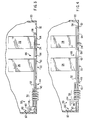
- Fig. 3 is a partial, planar, cutaway view of the computer of Fig. 2 showing a linkage structure in the locked position according to an embodiment of this invention;
- Fig. 4 is a partial, planar, cutaway view of the computer of Fig. 2 showing a linkage structure in the unlocked position according to an embodiment of this invention;
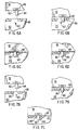
- Fig. 5 is a diagram of a rod and arm portion of the linkage structure acting upon modular units according to an alternative embodiment of this invention;
- Figs. 6a-d are diagrams showing the action between a display housing latch and keyboard housing catch structure according to an embodiment of this invention;
- Figs. 7a-c are diagrams showing the action between a display housing latch and keyboard housing catch structure according to an alternative embodiment of this invention;
- Fig. 8 is a schematic of a circuit for enabling/disabling access to desired system components;
- Fig. 9 is a schematic of a circuit for optionally enabling/disabling access to desired system components;
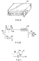
- Fig. 10 is a perspective view of the notebook computer of Fig. 2 inserted into a docking station;
- Fig. 11 is a diagram of a latch connection for securing the notebook computer to the docking station of Fig. 10;
- Fig. 12 is a schematic diagram of a circuit for controlling ejection of the notebook computer from the docking station according to an embodiment of this invention;
- Fig. 13 is a block diagram of an exemplary notebook computer architecture; and
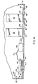
- Fig. 14 is a partial, planar, cutaway view of the computer of Fig. 2 showing a linkage structure in the unlocked position according to an alternate embodiment of this invention.
-
- Figs. 1 and 2 show a
portable computer 10 according to an embodiment of this invention. Theportable computer 10 is a notebook computer, laptop computer, hand-held computer, personal digital assistant or other general purpose or specialized portable computing device. The portable computer includes a processing unit (not shown),display 12 andkeyboard 14 integrated into acase 16. For a notebook computer embodiment thecase 16 includes adisplay housing 18 and akeyboard housing 20 attached via a hinged relationship. Aflat panel display 12 is mounted within thedisplay housing 18. Akeyboard 14, motherboard and I/O ports are mounted in thekeyboard housing 20. Modular units such as batteries, a floppy drive, hard drive, CD-ROM drive and modem or other PC card are readily installed and removed viaopenings keyboard housing 20. Fig. 2 shows anotebook computer 10 having ahard drive 26 andmodem 28 installed within theopenings - According to one aspect of the invention a
lock 30 is mounted within thekeyboard housing 20. Thelock 30 is accessible from one of the faces of thekeyboard housing 20. In the illustrated embodiment thelock 30 is accessible from afront face 32. In various embodiments the lock is a key lock, a combination lock, or an electronic keypad lock. Mechanical tumblers, electrical relays or other conventional or to be developed lock structures define the internal lock components. Illustrated is a mechanical combination lock with tumblers 34-37 which respond to a four entry combination. Also shown on thefront face 32 is aslide button 40. Theslide button 40 moves between an unlocked position 42 (shown in Fig. 1) and a locked position 44 (shown in Fig. 2). Theslide button 40 is movable from theunlocked position 42 to the lockedposition 44 regardless of the state of thelock 30. Theslide button 40, however, can move from the lockedposition 44 to theunlocked position 42 only when tumblers 34-37 are set to the correct combination, (e.g., or a key turns a key lock to an unlocked position; or a keypad lock receives the correct entry sequence). Switching theslide button 40 into the lockedposition 44 places thecomputer 10 into a locked state. Switching theslide button 40 into theunlocked position 42 places thecomputer 10 in the unlocked state. - In a preferred embodiment the
slide button 40 is biased toward the unlocked position. When a user unlocks thelock 30, theslide button 40 automatically moves into theunlocked position 42. Conversely when a user moves theslide button 40 into the lockedposition 44 in some embodiments thelock 30 automatically changes into a locked condition (e.g., the tumblers move, the key lock rotates or the key pad lock internal structure locks). In some embodiments thelock 30 does not automatically change into the locked condition when theslide button 40 moves into the lockedposition 44. The user instead manually changes the lock tumblers 34-37 or turns a key. Although aslide button 40 is shown, another mechanical, electrical, or optical switch, button, or latch is used in alternative embodiments. - Referring to Figs. 3 and 4 a
linkage structure 50 moves between a locked position and an unlocked position with theslide button 40. Thelinkage structure 50 includes arod 52 withmultiple arms arm 54 extends to adisplay latch opening 60.Other arms covers modular units openings covers arms arms rod 52. Thus, as therod 52 slides, thearms rod 52. The rod has two positions - a first 'locked' position 66 (see Fig. 3) corresponding to the slidingswitch 40 lockedposition 44; and a second 'unlocked' position 68 (see Fig. 4) corresponding to the slidingswitch 40unlocked position 42. When the rod is in the first lockedposition 66, thecovers modular units second position 68, thecovers modular units modular units - In the embodiment of Figs. 3 and 4, the
covers front face 32 of thekeyboard housing 20 while therod 52 is in either of thefirst position 66 or thesecond position 68. In an alternative embodiment, thecovers openings 22, 24 (i.e., while the rod is in the first position 66). In such alternative embodiment thecovers keyboard housing 20 out of plain sight when therod 52 moves into thesecond position 68. - While Figs. 3 and 4
show linking structure 50 having a mechanical connection betweenslide button 40 androd 52, an alternate embodiment has been contemplated and is shown in Fig. 14, whereslide button 40 is coupled to electric switch 46, which in turn remotely activatesrod 52 viasolenoid 48.Solenoid 48 is shown coupled to switch 46 viawire 47, although this connection could be made via wireless means, such as infrared. In this embodiment, linkingstructure 50 is still considered to be coupled to lock 30, although this coupling is at least in part obtained electronically. Those skilled in the art will appreciate that linkingstructure 50 can take still other forms, such as electromagnetic, piezo electric, etc., and still be coupled to lock 30, and still fall within the spirit and scope of the invention. - Fig. 5 shows another alternative embodiment in which
extensions 70, 72 are fixed relative to thearms covers modular unit area 74 with anadjacent wall 76. As therod 52 moves into thefirst position 66, theextensions 70, 72 move into the notch or recessedarea 74 adjacent to thewall 76 to block, limit or prevent removal of themodular units extension 70, 72 and thewall 76 block, limit or prevent the correspondingmodular unit openings arms extensions 70, 72. In such embodiment thearms area 74 into a blocking, limiting or preventing relation relative to thewalls 76. In yet another alternative embodiment, therod 52 rotates between first and second positions, instead of sliding, to move thearms extensions 70, 72 or covers 62, 64 into or out of a blocking, limiting or preventing position. The notch or recessedarea 74 occurs at or away from the sides and edges of amodular unit - Referring to Figs. 3, 4, 6 and 7, the function of
arm 54 is now described.Arm 54 serves to lock a display latch 82 (see Fig. 1) and prevent it from unlatching from thekeyboard housing 20. Thedisplay latch 82 is located on thedisplay housing 18 and includes a hookedportion 84. Thekeyboard housing 20 includes anopening 60 into which thelatch 82 is received. Theopening 60 is bordered in part by acatch structure 86. In one embodiment the latch's hookedportion 84 rotates between an extended position and a retracted position. The hookedportion 84 is biased to the extended position and is limited to rotate no further than the extended position (see Fig. 6a). - As the
display housing 18 is closed to thekeyboard housing 20, the hookedportion 84 bumps into thecatch structure 86. As the display housing continues to close, the force applied to the display acts upon the hookedportion 84 at thecatch structure 86 forcing the hookedportion 84 to rotate into the retracted position. (see Fig. 6b). As the display housing continues to close, the hookedportion 84 eventually clears thecatch structure 86. The internal bias within thelatch 82 then causes the hookedportion 84 to rotate back into the extended position (see Fig. 6c). Thedisplay housing 18 is now closed to thekeyboard housing 20. Fig. 6d shows thelatch 82 locked in place. According to an aspect of this invention, theextension 80 ofarm 54 moves into theopening 60 adjacent thelatch 82 when the rod moves into the first (i.e., locked) position 66 (see Figs. 3 and 6d). While theextension 80 is in theopening 60, the display cannot be opened. While the extension is not in the opening the display can be opened. - To open the display while the
rod 52 is in theunlocked position 68, the user moves alatch button 88 on thedisplay housing 18. Thelatch button 88 moves thelatch 82 laterally away from thecatch structure 86 allowing the hookedportion 84 to clear thecatch structure 86 freeing thedisplay housing 18 to open relative to thekeyboard housing 20. When therod 52 is in the lockedposition 66, thearm 54extension 80 fills the area into which thelatch 82 would move to clear thecatch structure 86. Thus, thelatch 82 is blocked while the rod is in the lockedposition 66 preventing the display from opening. - In some embodiments the hooked
portion 84 of thelatch 82 is an integral portion which does not move relative to the rest of thelatch 82. As the display is closed, the closing force is applied through thecatch structure 86 to the hookedportion 84. The force causes thelatch 82 andlatch button 88 to move bringing the hookedportion 84 path away from thecatch structure 86. When the display closes sufficiently, the hookedportion 84 clears thecatch structure 86 removing the force between thecatch structure 86 andlatch 82 / hookedportion 84. As a result, thelatch 82 moves into its relaxed position. In the closed, relaxed position (see fig. 6c) thecatch structure 86 blocks vertical extraction of the hookedportion 84. The user must manually movelatch button 88 to free thehooked portion 84 and allow the display to open. - One advantage of having a
latch 82 with a movable hookedportion 84 is that the display can be closed even when thelinkage structure 50 is in the lockedposition 66. Referring to Fig. 7a, theopening 60 in thekeyboard housing 20 is partially filled by thearm 54extension 80 while the display is open and thelinkage structure 50 is in the locked position . As the display closes, thelatch 82 fits into the remainder of theopening 60. To do so, the hookedportion 84 is rotated into the retracted position. Specifically, the closing force applied to the display is translated to the hookedportion 84 by the contact between the hookedportion 84 and the catch structure 86 (see Fig. 7b). Once the display is closed sufficiently, the hookedportion 84 clears thecatch structure 86 allowing the hookedportion 84 to return to its extended, biased relaxed position (see Fig. 7c). - With the
display housing 18 closed to thekeyboard housing 20 and thelinkage structure 50 in the lockedposition 66, thelatch button 88 cannot be moved to open the display because of the blocking presence of thearm 54extension 80. - Referring again to Figs. 3 and 4, the
linkage structure 50 also includes aspring 90 and theslide button 40. Thespring 90 is anchored at one end to thekeyboard housing 20 and at another end to an end of therod 52. Theslide button 40 is coupled to therod 52 forcing therod 52 to move with theslide button 40, and conversely, theslide button 40 to move with therod 52. Thespring 90 biases the rod toward the second, unlocked position 68 (see Fig. 4). Thus, when thelock 30 opens/unlocks, therod 52 is moved under the force ofspring 90 into theunlocked position 68. In broader terms, thespring 90 automatically moves thelinkage structure 50 into theunlocked position 68 when the correct combination is entered at thelock 30. - When the
slide switch 40 is moved from theunlocked position 42 to the lockedposition 44, therod 52 moves with theslide switch 40 to its lockedposition 66. In some embodiments the movement of the slide switch 40 (or rod 52) forces the tumblers 34-37 to move thereby putting thelock 30 in a locked state. - Fig. 8 is an electrical schematic of an enable/disable
circuit 100 responsive to the position of theslide button 40. Thecircuit 100 includes aswitch 102 having oneterminal 104 coupled to ground and another terminal 106 coupled to apower signal 108 and acomponent 110 being enabled/disabled. Theswitch 102 is positioned in either one of a first state or a second state. Movement of theslide button 40 into the lockedposition 44 puts theswitch 102 into the first state. Movement of theslide button 40 into theunlocked position 42 puts theswitch 102 into the second state. In the embodiment shown the first state corresponds to a closed switch and the second state corresponds to an open switch. When closed, thepower signal 108 flows to ground, thereby disabling the desiredcomponent 110. When open, thepower signal 108 flows to the desiredcomponent 110, thereby enabling such component. - According to an aspect of this invention, the
circuit 100 is located in the power signal path for thekeyboard 14 component, while anothersuch circuit 100 is located in the power signal path for each desired input device 112 (e.g., integral mouse, touchpad, eraser head, trackball; external mouse, touchpad, or trackball; other internal or external pointing device and clicking device). Additionally, one or more other components such as the motherboard, processing unit, I/O port, local bus, video bus, expansion bus, peripheral device are similarly disabled and enabled according to desired configurations. According to a preferred embodiment, the keyboard and pointing/clicking devices are enabled and disabled according to the position of theslide button 40. In an alternative embodiment the movement of theslide button 40 instead triggersCPU 218 interrupt. TheCPU 218 then processes the interrupt to disable one or more of an input device, bus, port, modular unit, component or device. - According to another aspect of the invention a user is given the option of whether some components are to be disabled during a locked
position 66 of theslide switch 40. Fig. 9 shows acircuit 116 used with components for which a user is given such option. Thecircuit 116 is the same as thecircuit 100, but includes anadditional switch 118 which determines whether theswitch 102 is active. Theswitch 118 is located in series with the switch 102 (e.g., as shown in Fig. 9), in parallel with theswitch 102. In other embodiments theswitch 118 instead is located in series or in parallel with theoptional component 120, or in series with the power source. In still another embodiment, a multi-position switch is used in place of theswitches switch 118 under software control. Acircuit 116 is located in the power signal path for each optionally controlledcomponent 120. When the user selects acomponent 120 to be disabled, theswitch 118 closes. Otherwise theswitch 118 is left is open. When closed theswitch 118 enables theswitch 102 to determine whether thecomponent 120 is enabled or disabled. When theswitch 118 is open thecomponent 120 is enabled regardless of the position ofswitch 102. As a result, thecomponent 120 is disabled only whencircuit 116 is configured to closeswitch 118 and theslide switch 40 closes theswitch 102. According to a preferred embodiment, a user is given the option of tying the system on/off switch 114 (see Fig. 1) to the state of theslide button 40 by placing thecircuit 116 in the signal path of the on/off switch. According to other configurations, thecircuit 116 is included in the power signal path of one or more other components such as the motherboard, processing unit, I/O port, local bus, video bus, expansion bus, or a peripheral device. - Referring to Fig. 10, the
notebook computer 10 is shown inserted within adocking station 120. The function of thedocking station 120 is to provide access to additional peripheral devices and to enhance the usability of the notebook computer system in a desktop environment. Because of the small size of notebook computers there often is not enough space to equip the system with all desired peripherals. The docking station provides access to additional peripherals, such as a floppy disk drive and CD-ROM drive. To enhance usability the docking station provides ports for hooking up an external keyboard and display monitor. Because thenotebook computer 10 integrateddisplay 12 andkeyboard 14 are typically small to promote transportability, it is desirable at times to use the notebook computer with an external keyboard and monitor. Rather than changing the cables every time a user moves the notebook computer, the docking station provides an unchanging connection to the monitor and keyboard. Simply by inserting thenotebook computer 10 into thedocking station 120, connections between the notebook computer and an external keyboard, display and one or more peripheral devices are established. - The
docking station 120 includes aneject button 122. When thebutton 122 is pushed, the notebook computer is ejected from thedocking station 120. Referring to Fig. 11, the docking station also includes one ormore latches 124 which mate intoindentations 126 on the notebookcomputer keyboard housing 20. When theeject button 122 is pushed, thelatch 124 releases from theindentation 126 and an actuator pushes the notebook computer outward from thedocking station 120. In one embodiment the actuator serves to both move thelatches 124 and eject thenotebook computer 10. A user is unable to remove the notebook computer from thedocking station 120 while the latch(es) 124 mate into the indentation(s) 126. - According to an aspect of this invention, the
eject button 122 is disabled while the notebook computer'sslide button 40 is in the lockedposition 44. Fig. 12 showscircuit notebook computer 10.Circuit 130 is located within thedocking station 120.Circuit 131 is located within thenotebook computer 10. Thecircuit 130 couples to thecircuit 131 viacontacts docking station 120 andcontacts notebook computer 10. The contacts 138 - 144 are formed by pin connections between thenotebook computer 10 anddocking station 120. In one embodiment the pin connection are part of a multiple pin connector used for exchanging signals between the notebook computer and docking station. In another embodiment the pins/contacts 138-144 replace or supplement guide pins used for aligning an electrical connection between the notebook computer anddocking station 120. - The
circuit 130 includes aswitch 132 and anejection actuator 134. Theswitch 132 is coupled to a power signal. When theswitch 132 is closed the power signal is fed through theactuator 134. When thecircuit 130 is closed (via circuit 131), the signal path 146 is tied to ground, theactuator 134 is energized and thenotebook computer 10 is ejected. When thecircuit 130 is left open (e.g., at circuit 131) the actuator does not become active and the notebook is not ejected. - The
circuit 131 includes aswitch 150 within thenotebook computer 10. The state ofsuch switch 150 is defined by the position of theslide button 40. When theslide button 40 is in theunlocked position 42, theswitch 150 is closed. When theslide button 40 is in the lockedposition 44, theswitch 150 is open. First consider the condition where the slide button is in theunlocked position 42 and thus, theswitch 150 is closed. When a user pushes theeject button 122, theswitch 132 closes causing current to flow from the power source into theactuator 134, along path 146, acrosscontacts closed switch 150 acrosscontact actuator 134 to release and eject thenotebook computer 10. - Next consider the condition where the
slide button 40 is in the lockedposition 44, and thus, switch 150 is open. When a user pushes theeject button 122, theswitch 132 closes causing current to flow from the power source into theactuator 134, along path 146, and acrosscontacts Switch 150 in the notebook computer, however, is open resulting in anopen circuit 131 and no return path for the current. Thus, thecircuit 130 also is left open and the actuator does not activate. In effect, the actuator and the eject button are disabled. - Fig. 13 a system architecture for the
notebook computer 10 configured to operate with multiple peripheral device. Thecomputer 10 includes aprocessor 218, system memory (e.g., 224, 250), multiple communication busses 252, 254, 256, 258 and several system components and peripherals. The number and types of communication busses, system components and peripherals varies for differing embodiments. For thecomputer 10 shown, there is aprocessor bus 252,local bus 254, I/O bus 256 andexpansion bus 258. Theprocessor 218,external cache 250 andsystem RAM 224 are located on theprocessor bus 252. The I/O bus 256 is linked to theprocessor bus 252 for interfacing to I/O ports. Aprinter 266, pointingdevice 220 and clicking device 222 (e.g., mouse) typically are coupled to the I/O bus 256. - The
local bus 254 is linked to theprocessor bus 252 via alocal bus interface 270. Exemplary local busses are the video local (VL) or VESA-standard bus, the peripheral component interface (PCI) bus and the NU-BUS. The PCI bus, for example, may couple up to 10 peripheral devices. Illustrated are agraphics controller 272,video processor 274, infrareddigital communication interface 276, and asound card 278.Speakers 280 and amicrophone 282 are linked to thesound card 278. Thevideo subsystems flat panel display 12 from the video subsystems and sharedmemory 290 via avideo DAC 294. - The
expansion bus 258 is linked to theprocessor bus 252 via thelocal bus 254 and anexpansion bus interface 296. Peripherals, system components and mass storage devices typically are coupled to theexpansion bus 258. Shown are adrive controller 298 coupling to a hard disk drive (mass storage device) 26 and afloppy disk drive 202, aSCSI controller 208 coupling to anoptical storage device 210 or other SCSI peripheral, and a fax/modem 28. As an alternative to theSCSI controller 208, any of several proprietary controllers also may couple to anoptical storage device 210. According to other architectures thehard drive 26 and/or the optical storage device 210 (e.g., CD-ROM) and there respective controllers instead are coupled to thelocal bus 254. - The architecture shown is an exemplary architecture. The
notebook computer 10 embodies a proprietary or open architecture for a personal computer, PENTIUM computer, APPLE MACINTOSH computer, or other computer currently available or to come based on the Intel 80X86 architecture, Motorola 68XXX architecture, PowerPC architecture or other CISC processor architectures, RISC processor architectures and other single or multiple multiprocessor architectures. Alternatively thecomputer 10 embodies simpler architectures for hand-held computing devices or INTERNET communication devices. - The
notebook computer 10 has a locked state defined when theslide button 40, and thuslinkage structure 50, are in the lockedpositions openings 22, 24) of thecomputer housing 20. In addition the input via the keyboard and pointing/clicking devices are disabled and thenotebook computer 10, if docked, is prevented from undocking. If and when thedisplay housing 18 is closed to thekeyboard housing 20, thedisplay housing 18 also is locked in place to prevent re-opening. Lastly, any optional features selected by the user to be incorporated into the security system are activated (e.g., the on/off switch is disabled). In a preferred configuration the user is still able to allow unattended operations, such as receiving e-mail, awaiting a fax or perform data synchronization via a docking port. Thenotebook computer 10 has an unlocked state defined when theslide switch 40, and thuslinkage structure 50, are in theunlocked positions - One advantage of the invention is that only a single action is performed to switch the
computer 10 into the locked state or the unlocked state. Another advantage is that the user can still allow unattended functions to be performed while security measures are active. Another advantage is that a user can configure some security measures to select optional components to be disabled with the security system (i.e., when the computer enters the locked state).
Claims (8)
- A portable computing apparatus (10), comprising:wherein the case defines an opening (22), the modular unit removably inserted within the opening, and wherein the case comprises: a first housing (18) within which is mounted the display; and a second housing (20) within which is mounted the input device, the processing unit and the modular unit, the second housing defining the opening within which the modular unit is removably inserted; and wherein the first housing moves relative to the second housing between an open position for viewing the display and a closed position for storage; and wherein the linkage is mounted within the second housing and prevents opening of the first housing relative to the second housing when the first housing is in the closed position and the linkage is in a first position;a case (16), a display (12), an input device (14/112), a processing unit (218), a modular unit (26), a lock (30) and a linkage (50);
wherein the linkage is coupled to the lock, the linkage movable between the first position (44) and a second position (42), the linkage preventing removal of the modular unit while in the first position; and
wherein the linkage is prevented from moving into the second position while the lock defines a locked condition. - The apparatus of claim 1, in which the linkage automatically moves into the second position when the lock switches into the unlocked condition.
- The apparatus of claims 1 or 2, further comprising a circuit (100) for limiting operation of the apparatus while the linkage is in the first position.
- The apparatus of claims 1, 2 or 3, further comprising a circuit (131) having a first state in which the computing apparatus is precluded from being undocked from a docking station (120) and a second state in which the circuit does not preclude the computing apparatus from being undocked from the docking station, the circuit being in the first state while the linkage is in the first position and being in the second state while the linkage is in the second position.
- The apparatus of claims 1, 2, 3 or 4, in which the linkage comprises a switch (40) defining a switch first position and a switch second position, and a link (52) which moves between the switch first position and the switch second position, the linkage further comprising a first member (62) fixed relative to the link which limits removal of the modular unit while the switch is in the switch first position and a second member (80) fixed relative to the link (52) which limits movement of the first housing out of the closed position while the first housing is in the closed position relative to the second housing and the switch is in the first switch position.
- A method for securing access to a portable computing apparatus (10), the apparatus comprising a case (16), a lock (30), a linkage (50) and a circuit (100), and wherein an input device (14), a processing unit (218), a modular unit (26), the lock (30) and the linkage (50) are mounted within the case, wherein the case defines an opening (22), the modular unit removably inserted within the opening, wherein the case comprises: a first housing (18) within which is mounted the display; and a second housing (20) within which is mounted the input device, the processing unit and the modular unit, the second housing defining the opening within which the modular unit is removably inserted; and wherein the first housing moves relative to the second housing between an open position for viewing the display and a closed position for storage; and wherein the linkage is mounted within the second housing and prevents opening of the first housing relative to the second housing when the first housing is in the closed position and the linkage is in a first position;
wherein the lock defines at a given time either one of a locked condition and an unlocked condition, and wherein the linkage is coupled to the lock and movable between the first position (44) and a second position (42), and wherein the circuit has a first state and a second state, the method comprising the steps of:wherein the step of defining the locked state comprises the steps of:defining a locked state for the computing apparatus via a first action, wherein the first action comprises switching the lock to define the locked condition, and wherein the linkage is prevented from moving into the second position while the lock defines the locked condition; anddefining an unlocked state for the computing apparatus via a second action, the second action comprising switching the lock into the unlocked condition;wherein the step of defining the unlocked state comprises the steps of :moving the linkage into the first position, wherein the linkage restricts removal of the modular unit; andentering the circuit into the first state, during which operation of a component of the computing apparatus is disabled;moving the linkage into the second position, wherein the linkage does not limit removal of the modular unit; andentering the circuit into the second state, during which the circuit does not disable the component. - The method of claim 6, further comprising the step of:wherein while said linkage is in the first position and the first housing is in the closed position, the linkage prevents movement of the first housing into the open position.moving the first housing relative to the second housing between an open position and a closed position,
- The method of claims 6 or 7, in which the circuit is a first circuit and in which the computing apparatus further comprises a second circuit (131) having a first state during which the computing apparatus is precluded from being undocked from a docking station and a second state during which the circuit does not preclude the computing apparatus from being undocked from the docking station, the circuit being in the first state while the linkage is in the first position and being in the second state while the linkage is in the second position, and wherein the step of defining the locked state further comprises the step of entering the second circuit into the first state, wherein the step of defining the unlocked state further comprises the step of entering the second circuit into the second state.
Applications Claiming Priority (2)
| Application Number | Priority Date | Filing Date | Title |
|---|---|---|---|
| US08/742,786 US5757616A (en) | 1996-10-31 | 1996-10-31 | Physical security system for portable computer |
| US742786 | 1996-10-31 |
Publications (3)
| Publication Number | Publication Date |
|---|---|
| EP0840197A2 EP0840197A2 (en) | 1998-05-06 |
| EP0840197A3 EP0840197A3 (en) | 2000-04-19 |
| EP0840197B1 true EP0840197B1 (en) | 2005-08-10 |
Family
ID=24986221
Family Applications (1)
| Application Number | Title | Priority Date | Filing Date |
|---|---|---|---|
| EP97308188A Expired - Lifetime EP0840197B1 (en) | 1996-10-31 | 1997-10-15 | Physical security system for portable computer |
Country Status (6)
| Country | Link |
|---|---|
| US (1) | US5757616A (en) |
| EP (1) | EP0840197B1 (en) |
| JP (1) | JP4071325B2 (en) |
| KR (1) | KR19980033391A (en) |
| CN (1) | CN1143226C (en) |
| DE (1) | DE69733929T2 (en) |
Families Citing this family (152)
| Publication number | Priority date | Publication date | Assignee | Title |
|---|---|---|---|---|
| JPH09269848A (en) * | 1996-03-28 | 1997-10-14 | Internatl Business Mach Corp <Ibm> | Docking device for portable computer |
| JP3369080B2 (en) * | 1997-07-22 | 2003-01-20 | 富士通株式会社 | Electronic equipment |
| JPH1185314A (en) * | 1997-09-01 | 1999-03-30 | Funai Electric Co Ltd | Portable electronic information unit |
| US6014747A (en) * | 1997-09-30 | 2000-01-11 | Intel Corporation | Method and apparatus for system's and chassis protection utilizing system management interrupts |
| JP3966393B2 (en) * | 1997-11-07 | 2007-08-29 | 富士通株式会社 | Anti-theft mechanism for information processing equipment |
| KR19990080369A (en) * | 1998-04-16 | 1999-11-05 | 윤종용 | Computer with mouse lock function and control method |
| US6122163A (en) * | 1998-07-27 | 2000-09-19 | Compaq Computer Corporation | Security mounting structure for electronic apparatus component |
| US6135958A (en) | 1998-08-06 | 2000-10-24 | Acuson Corporation | Ultrasound imaging system with touch-pad pointing device |
| US6182481B1 (en) * | 1998-10-27 | 2001-02-06 | Neil Frank Nagy | Security lock for laptop and notebook computers |
| US6252765B1 (en) * | 1998-12-29 | 2001-06-26 | Intel Corporation | Device bay retention mechanism |
| JP3378822B2 (en) * | 1999-02-05 | 2003-02-17 | インターナショナル・ビジネス・マシーンズ・コーポレーション | Information processing system expansion unit, information processing system attachable to information processing system expansion unit, and existence management method of information processing system |
| US6294995B1 (en) | 1999-03-15 | 2001-09-25 | Jennifer Patterson | Anti-theft alarm for portable computer |
| USRE40012E1 (en) * | 1999-03-15 | 2008-01-22 | J2D Llc | Anti-theft alarm for portable computer |
| US6115248A (en) | 1999-05-17 | 2000-09-05 | Palm, Inc. | Detachable securement of an accessory device to a handheld computer |
| US6053017A (en) * | 1999-07-13 | 2000-04-25 | Ling; Chong-Kuan | Combination lock means for floppy disk drive |
| US6690411B2 (en) * | 1999-07-20 | 2004-02-10 | @Security Broadband Corp. | Security system |
| US8520068B2 (en) * | 1999-07-20 | 2013-08-27 | Comcast Cable Communications, Llc | Video security system |
| US7015806B2 (en) * | 1999-07-20 | 2006-03-21 | @Security Broadband Corporation | Distributed monitoring for a video security system |
| US9300921B2 (en) | 1999-07-20 | 2016-03-29 | Comcast Cable Communications, Llc | Video security systems and methods |
| JP3582782B2 (en) * | 1999-08-20 | 2004-10-27 | ワールドピーコム株式会社 | Hospitality management device for restaurants |
| US6578054B1 (en) | 1999-10-04 | 2003-06-10 | Microsoft Corporation | Method and system for supporting off-line mode of operation and synchronization using resource state information |
| US6237375B1 (en) | 1999-12-10 | 2001-05-29 | William E. Wymer | Lap top lock |
| US6362747B1 (en) * | 2000-05-15 | 2002-03-26 | Digital Security Controls Ltd. | Security alarm keypad with message alert |
| US6490155B2 (en) | 2000-07-07 | 2002-12-03 | Palm, Inc. | Detachable coupling for handheld computer and peripheral attachment scheme |
| US20020104005A1 (en) * | 2001-01-31 | 2002-08-01 | Yin Memphis Zhihong | Direction-sensitive, touch-activated security device and method of use therefor |
| JP4075335B2 (en) * | 2001-04-11 | 2008-04-16 | 松下電器産業株式会社 | Electronics |
| DE10147790B4 (en) * | 2001-09-27 | 2005-06-23 | Fujitsu Siemens Computers Gmbh | Portable computer |
| KR20030043207A (en) * | 2001-11-27 | 2003-06-02 | 삼성전자주식회사 | computer system and controlling method thereof |
| US6658091B1 (en) | 2002-02-01 | 2003-12-02 | @Security Broadband Corp. | LIfestyle multimedia security system |
| US6909910B2 (en) * | 2002-02-01 | 2005-06-21 | Microsoft Corporation | Method and system for managing changes to a contact database |
| US7534211B2 (en) * | 2002-03-29 | 2009-05-19 | Sonosite, Inc. | Modular apparatus for diagnostic ultrasound |
| US6646862B1 (en) * | 2002-05-31 | 2003-11-11 | Dell Products L.P. | Dynamic circuit interface |
| US6885552B2 (en) * | 2002-12-20 | 2005-04-26 | Dell Products L.P. | System and method for a multi-functional security mechanism in a docking station |
| US20050041390A1 (en) * | 2003-08-21 | 2005-02-24 | First International Computer, Inc. | Structure of notebook computer |
| US7644376B2 (en) * | 2003-10-23 | 2010-01-05 | Microsoft Corporation | Flexible architecture for notifying applications of state changes |
| US20050097930A1 (en) * | 2003-11-06 | 2005-05-12 | International Business Machines Corporation | Anti-theft method and system for portable electronic devices |
| CN1332279C (en) * | 2004-01-09 | 2007-08-15 | 佛山市顺德区顺达电脑厂有限公司 | Warning function operating method for portable computer |
| US20090077623A1 (en) | 2005-03-16 | 2009-03-19 | Marc Baum | Security Network Integrating Security System and Network Devices |
| US9191228B2 (en) | 2005-03-16 | 2015-11-17 | Icontrol Networks, Inc. | Cross-client sensor user interface in an integrated security network |
| US8963713B2 (en) | 2005-03-16 | 2015-02-24 | Icontrol Networks, Inc. | Integrated security network with security alarm signaling system |
| US10156959B2 (en) | 2005-03-16 | 2018-12-18 | Icontrol Networks, Inc. | Cross-client sensor user interface in an integrated security network |
| US11811845B2 (en) | 2004-03-16 | 2023-11-07 | Icontrol Networks, Inc. | Communication protocols over internet protocol (IP) networks |
| US11916870B2 (en) | 2004-03-16 | 2024-02-27 | Icontrol Networks, Inc. | Gateway registry methods and systems |
| US11368327B2 (en) | 2008-08-11 | 2022-06-21 | Icontrol Networks, Inc. | Integrated cloud system for premises automation |
| US11489812B2 (en) | 2004-03-16 | 2022-11-01 | Icontrol Networks, Inc. | Forming a security network including integrated security system components and network devices |
| US10127802B2 (en) | 2010-09-28 | 2018-11-13 | Icontrol Networks, Inc. | Integrated security system with parallel processing architecture |
| US7711796B2 (en) | 2006-06-12 | 2010-05-04 | Icontrol Networks, Inc. | Gateway registry methods and systems |
| US11113950B2 (en) | 2005-03-16 | 2021-09-07 | Icontrol Networks, Inc. | Gateway integrated with premises security system |
| US9729342B2 (en) | 2010-12-20 | 2017-08-08 | Icontrol Networks, Inc. | Defining and implementing sensor triggered response rules |
| US11159484B2 (en) | 2004-03-16 | 2021-10-26 | Icontrol Networks, Inc. | Forming a security network including integrated security system components and network devices |
| US11582065B2 (en) | 2007-06-12 | 2023-02-14 | Icontrol Networks, Inc. | Systems and methods for device communication |
| US10721087B2 (en) | 2005-03-16 | 2020-07-21 | Icontrol Networks, Inc. | Method for networked touchscreen with integrated interfaces |
| US11244545B2 (en) | 2004-03-16 | 2022-02-08 | Icontrol Networks, Inc. | Cross-client sensor user interface in an integrated security network |
| US11201755B2 (en) | 2004-03-16 | 2021-12-14 | Icontrol Networks, Inc. | Premises system management using status signal |
| US11277465B2 (en) | 2004-03-16 | 2022-03-15 | Icontrol Networks, Inc. | Generating risk profile using data of home monitoring and security system |
| US9141276B2 (en) | 2005-03-16 | 2015-09-22 | Icontrol Networks, Inc. | Integrated interface for mobile device |
| US11677577B2 (en) | 2004-03-16 | 2023-06-13 | Icontrol Networks, Inc. | Premises system management using status signal |
| US10444964B2 (en) | 2007-06-12 | 2019-10-15 | Icontrol Networks, Inc. | Control system user interface |
| US10382452B1 (en) | 2007-06-12 | 2019-08-13 | Icontrol Networks, Inc. | Communication protocols in integrated systems |
| US10339791B2 (en) | 2007-06-12 | 2019-07-02 | Icontrol Networks, Inc. | Security network integrated with premise security system |
| US10522026B2 (en) | 2008-08-11 | 2019-12-31 | Icontrol Networks, Inc. | Automation system user interface with three-dimensional display |
| US10313303B2 (en) | 2007-06-12 | 2019-06-04 | Icontrol Networks, Inc. | Forming a security network including integrated security system components and network devices |
| US10142392B2 (en) | 2007-01-24 | 2018-11-27 | Icontrol Networks, Inc. | Methods and systems for improved system performance |
| US11368429B2 (en) | 2004-03-16 | 2022-06-21 | Icontrol Networks, Inc. | Premises management configuration and control |
| US11343380B2 (en) | 2004-03-16 | 2022-05-24 | Icontrol Networks, Inc. | Premises system automation |
| US20160065414A1 (en) | 2013-06-27 | 2016-03-03 | Ken Sundermeyer | Control system user interface |
| US8988221B2 (en) | 2005-03-16 | 2015-03-24 | Icontrol Networks, Inc. | Integrated security system with parallel processing architecture |
| US9609003B1 (en) | 2007-06-12 | 2017-03-28 | Icontrol Networks, Inc. | Generating risk profile using data of home monitoring and security system |
| US9531593B2 (en) | 2007-06-12 | 2016-12-27 | Icontrol Networks, Inc. | Takeover processes in security network integrated with premise security system |
| AU2005223267B2 (en) | 2004-03-16 | 2010-12-09 | Icontrol Networks, Inc. | Premises management system |
| US10375253B2 (en) | 2008-08-25 | 2019-08-06 | Icontrol Networks, Inc. | Security system with networked touchscreen and gateway |
| US11316958B2 (en) | 2008-08-11 | 2022-04-26 | Icontrol Networks, Inc. | Virtual device systems and methods |
| US10200504B2 (en) | 2007-06-12 | 2019-02-05 | Icontrol Networks, Inc. | Communication protocols over internet protocol (IP) networks |
| US10237237B2 (en) | 2007-06-12 | 2019-03-19 | Icontrol Networks, Inc. | Communication protocols in integrated systems |
| US8635350B2 (en) | 2006-06-12 | 2014-01-21 | Icontrol Networks, Inc. | IP device discovery systems and methods |
| CA2464703A1 (en) * | 2004-04-22 | 2005-10-22 | Alexander Loudon | Cross-u lock block |
| US20060050474A1 (en) * | 2004-09-08 | 2006-03-09 | Hiroyuki Kusaka | Computer with restriction feature for restricting user access |
| ES2304152T3 (en) * | 2004-10-06 | 2008-09-16 | Nokia Corporation | ACCESS CONTROL TO A DATA TERMINAL. |
| US20060133019A1 (en) * | 2004-12-21 | 2006-06-22 | Fuminori Yamazaki | Latch assembly for an electronic device |
| EP1840703B1 (en) * | 2005-01-14 | 2013-10-09 | Fujitsu Component Limited | Operating body, information inputting device and information terminal device |
| US7296447B2 (en) * | 2005-02-24 | 2007-11-20 | The Stanley Works | Vending machine lock assembly |
| US20110128378A1 (en) | 2005-03-16 | 2011-06-02 | Reza Raji | Modular Electronic Display Platform |
| US20120324566A1 (en) | 2005-03-16 | 2012-12-20 | Marc Baum | Takeover Processes In Security Network Integrated With Premise Security System |
| US10999254B2 (en) | 2005-03-16 | 2021-05-04 | Icontrol Networks, Inc. | System for data routing in networks |
| US20170180198A1 (en) | 2008-08-11 | 2017-06-22 | Marc Baum | Forming a security network including integrated security system components |
| US11496568B2 (en) | 2005-03-16 | 2022-11-08 | Icontrol Networks, Inc. | Security system with networked touchscreen |
| US11700142B2 (en) | 2005-03-16 | 2023-07-11 | Icontrol Networks, Inc. | Security network integrating security system and network devices |
| US9306809B2 (en) | 2007-06-12 | 2016-04-05 | Icontrol Networks, Inc. | Security system with networked touchscreen |
| US11615697B2 (en) | 2005-03-16 | 2023-03-28 | Icontrol Networks, Inc. | Premise management systems and methods |
| US7307846B2 (en) * | 2005-07-20 | 2007-12-11 | Inventec Corporation | Sliding cover for slot of electronic device |
| TWI319183B (en) * | 2005-12-06 | 2010-01-01 | Asustek Comp Inc | Portable electronic apparatus/withdrawer |
| JP2007264964A (en) * | 2006-03-28 | 2007-10-11 | Fujitsu Ltd | Device provided with locking mechanism of casing |
| US20070247803A1 (en) * | 2006-04-24 | 2007-10-25 | Immanuel Eickholdt | Portable computing device housing assembly, and associated methodology, providing for carriage of an external mass storage device |
| US10079839B1 (en) | 2007-06-12 | 2018-09-18 | Icontrol Networks, Inc. | Activation of gateway device |
| US8179672B2 (en) | 2006-06-30 | 2012-05-15 | National Products, Inc. | Portable device docking station |
| US7298611B1 (en) * | 2006-06-30 | 2007-11-20 | Carnevali Jeffrey D | Portable device docking station |
| CN101105703A (en) * | 2006-07-14 | 2008-01-16 | 鸿富锦精密工业(深圳)有限公司 | Notebook computer with cipher lock |
| US20080104716A1 (en) * | 2006-07-31 | 2008-05-01 | Michael Hall | Apparatus for improved security and connectivity of a computer display and other secured items |
| US20080109664A1 (en) * | 2006-07-31 | 2008-05-08 | Michael Hall | Apparatus for improved security and connectivity of secured items |
| US11706279B2 (en) | 2007-01-24 | 2023-07-18 | Icontrol Networks, Inc. | Methods and systems for data communication |
| CN101241396B (en) * | 2007-02-06 | 2012-05-23 | 鸿富锦精密工业(深圳)有限公司 | Keyboard capable of locking key |
| US7633385B2 (en) | 2007-02-28 | 2009-12-15 | Ucontrol, Inc. | Method and system for communicating with and controlling an alarm system from a remote server |
| US7684189B2 (en) * | 2007-04-18 | 2010-03-23 | Sinox Co., Ltd. | Portable electronic device for locking up locking component |
| US8451986B2 (en) | 2007-04-23 | 2013-05-28 | Icontrol Networks, Inc. | Method and system for automatically providing alternate network access for telecommunications |
| US8174837B2 (en) * | 2007-04-27 | 2012-05-08 | Hewlett-Packard Development Company, L.P. | Wireless enable/disable locking system |
| US11237714B2 (en) | 2007-06-12 | 2022-02-01 | Control Networks, Inc. | Control system user interface |
| US10051078B2 (en) | 2007-06-12 | 2018-08-14 | Icontrol Networks, Inc. | WiFi-to-serial encapsulation in systems |
| US11218878B2 (en) | 2007-06-12 | 2022-01-04 | Icontrol Networks, Inc. | Communication protocols in integrated systems |
| US10423309B2 (en) | 2007-06-12 | 2019-09-24 | Icontrol Networks, Inc. | Device integration framework |
| US11212192B2 (en) | 2007-06-12 | 2021-12-28 | Icontrol Networks, Inc. | Communication protocols in integrated systems |
| US10389736B2 (en) | 2007-06-12 | 2019-08-20 | Icontrol Networks, Inc. | Communication protocols in integrated systems |
| US11601810B2 (en) | 2007-06-12 | 2023-03-07 | Icontrol Networks, Inc. | Communication protocols in integrated systems |
| US10666523B2 (en) | 2007-06-12 | 2020-05-26 | Icontrol Networks, Inc. | Communication protocols in integrated systems |
| US11089122B2 (en) | 2007-06-12 | 2021-08-10 | Icontrol Networks, Inc. | Controlling data routing among networks |
| US11316753B2 (en) | 2007-06-12 | 2022-04-26 | Icontrol Networks, Inc. | Communication protocols in integrated systems |
| US11646907B2 (en) | 2007-06-12 | 2023-05-09 | Icontrol Networks, Inc. | Communication protocols in integrated systems |
| US10523689B2 (en) | 2007-06-12 | 2019-12-31 | Icontrol Networks, Inc. | Communication protocols over internet protocol (IP) networks |
| US10616075B2 (en) | 2007-06-12 | 2020-04-07 | Icontrol Networks, Inc. | Communication protocols in integrated systems |
| US11423756B2 (en) | 2007-06-12 | 2022-08-23 | Icontrol Networks, Inc. | Communication protocols in integrated systems |
| US10498830B2 (en) | 2007-06-12 | 2019-12-03 | Icontrol Networks, Inc. | Wi-Fi-to-serial encapsulation in systems |
| US7606024B2 (en) * | 2007-08-16 | 2009-10-20 | International Business Machines Corporation | Computer lock system |
| US11831462B2 (en) | 2007-08-24 | 2023-11-28 | Icontrol Networks, Inc. | Controlling data routing in premises management systems |
| US11916928B2 (en) | 2008-01-24 | 2024-02-27 | Icontrol Networks, Inc. | Communication protocols over internet protocol (IP) networks |
| US8984653B2 (en) * | 2008-04-03 | 2015-03-17 | Microsoft Technology Licensing, Llc | Client controlled lock for electronic devices |
| JP5350464B2 (en) * | 2008-04-29 | 2013-11-27 | ヒューレット−パッカード デベロップメント カンパニー エル.ピー. | Ejection mechanism for computer equipment |
| US20090301477A1 (en) * | 2008-06-05 | 2009-12-10 | Brian William Pierro | Heat and moisture exchange unit with check valve |
| US20170185278A1 (en) | 2008-08-11 | 2017-06-29 | Icontrol Networks, Inc. | Automation system user interface |
| US11729255B2 (en) | 2008-08-11 | 2023-08-15 | Icontrol Networks, Inc. | Integrated cloud system with lightweight gateway for premises automation |
| US11758026B2 (en) | 2008-08-11 | 2023-09-12 | Icontrol Networks, Inc. | Virtual device systems and methods |
| US11792036B2 (en) | 2008-08-11 | 2023-10-17 | Icontrol Networks, Inc. | Mobile premises automation platform |
| US10530839B2 (en) | 2008-08-11 | 2020-01-07 | Icontrol Networks, Inc. | Integrated cloud system with lightweight gateway for premises automation |
| US11258625B2 (en) | 2008-08-11 | 2022-02-22 | Icontrol Networks, Inc. | Mobile premises automation platform |
| US8638211B2 (en) | 2009-04-30 | 2014-01-28 | Icontrol Networks, Inc. | Configurable controller and interface for home SMA, phone and multimedia |
| US7961461B2 (en) * | 2009-09-04 | 2011-06-14 | Dell Products L.P. | Secure media bay and media module |
| US8882069B2 (en) | 2010-01-29 | 2014-11-11 | ACCO Brands Corporation | Securing apparatus for portable electronic devices |
| AU2011250886A1 (en) | 2010-05-10 | 2013-01-10 | Icontrol Networks, Inc | Control system user interface |
| US8432688B2 (en) * | 2010-07-08 | 2013-04-30 | Dell Products L.P. | IHS securing system |
| US8836467B1 (en) | 2010-09-28 | 2014-09-16 | Icontrol Networks, Inc. | Method, system and apparatus for automated reporting of account and sensor zone information to a central station |
| US8427826B2 (en) | 2010-11-29 | 2013-04-23 | L&P Property Management Company | Computer docking station assembly |
| US11750414B2 (en) | 2010-12-16 | 2023-09-05 | Icontrol Networks, Inc. | Bidirectional security sensor communication for a premises security system |
| US9147337B2 (en) | 2010-12-17 | 2015-09-29 | Icontrol Networks, Inc. | Method and system for logging security event data |
| US9163433B2 (en) | 2012-10-31 | 2015-10-20 | Invue Security Products Inc. | Display stand for a tablet computer |
| US9360891B1 (en) * | 2013-02-13 | 2016-06-07 | Steven Van Der Merwe | Recessed USB port |
| WO2014142960A1 (en) | 2013-03-15 | 2014-09-18 | Intel Corporation | Mechanisms for locking computing devices |
| US9567776B2 (en) | 2013-06-11 | 2017-02-14 | Invue Security Products Inc. | Anti-theft device for portable electronic device |
| US9778683B2 (en) | 2013-11-25 | 2017-10-03 | Hewlett-Packard Development Company, L.P. | Locking mechanisms to lock key movement of keyboards |
| US11146637B2 (en) | 2014-03-03 | 2021-10-12 | Icontrol Networks, Inc. | Media content management |
| US11405463B2 (en) | 2014-03-03 | 2022-08-02 | Icontrol Networks, Inc. | Media content management |
| EP3166499A4 (en) * | 2014-07-09 | 2018-02-28 | Edan Instruments, Inc. | Portable ultrasound user interface and resource management systems and methods |
| US9683393B2 (en) | 2014-10-31 | 2017-06-20 | ACCO Brands Corporation | System for physically securing an electronic device |
| GB2533559A (en) * | 2014-12-16 | 2016-06-29 | Displaylink Uk Ltd | A device capable of being operated in different modes |
| US10510230B1 (en) | 2018-11-15 | 2019-12-17 | Hewlett Packard Enterprise Development Lp | Enclosures for coupling to asset walls |
Family Cites Families (5)
| Publication number | Priority date | Publication date | Assignee | Title |
|---|---|---|---|---|
| US5321827A (en) * | 1989-08-02 | 1994-06-14 | Advanced Logic Research, Inc. | Computer system with modular upgrade capability |
| JPH04169917A (en) * | 1990-05-07 | 1992-06-17 | Toshiba Corp | Portable electronic apparatus |
| JPH087646B2 (en) * | 1992-10-29 | 1996-01-29 | インターナショナル・ビジネス・マシーンズ・コーポレイション | Stationary device for portable computer |
| US5406261A (en) * | 1993-01-11 | 1995-04-11 | Glenn; James T. | Computer security apparatus and method |
| JP2596702B2 (en) * | 1993-07-23 | 1997-04-02 | インターナショナル・ビジネス・マシーンズ・コーポレイション | Information processing device |
-
1996
- 1996-10-31 US US08/742,786 patent/US5757616A/en not_active Expired - Lifetime
-
1997
- 1997-10-15 DE DE69733929T patent/DE69733929T2/en not_active Expired - Fee Related
- 1997-10-15 EP EP97308188A patent/EP0840197B1/en not_active Expired - Lifetime
- 1997-10-17 JP JP28560397A patent/JP4071325B2/en not_active Expired - Fee Related
- 1997-10-28 CN CNB971215235A patent/CN1143226C/en not_active Expired - Fee Related
- 1997-10-31 KR KR1019970057162A patent/KR19980033391A/en active IP Right Grant
Also Published As
| Publication number | Publication date |
|---|---|
| DE69733929T2 (en) | 2006-06-22 |
| EP0840197A2 (en) | 1998-05-06 |
| JPH10143280A (en) | 1998-05-29 |
| DE69733929D1 (en) | 2005-09-15 |
| CN1181549A (en) | 1998-05-13 |
| US5757616A (en) | 1998-05-26 |
| JP4071325B2 (en) | 2008-04-02 |
| CN1143226C (en) | 2004-03-24 |
| KR19980033391A (en) | 1998-07-25 |
| EP0840197A3 (en) | 2000-04-19 |
Similar Documents
| Publication | Publication Date | Title |
|---|---|---|
| EP0840197B1 (en) | Physical security system for portable computer | |
| US6264488B1 (en) | Computer underside docking method and apparatus | |
| US6331934B1 (en) | Computer docking station with anti-theft locking mechanisms for removable components | |
| US6724623B2 (en) | Wedge-shaped port replicator for portable computer | |
| US6151218A (en) | Physical security system for portable computer/port replicator | |
| US5995366A (en) | Computer anti-theft system and method | |
| US10019035B2 (en) | Tablet attachment system | |
| US20020131234A1 (en) | Portable computer docking station with protected connector | |
| US5841631A (en) | Latch block control for media bay module | |
| US6046571A (en) | Port replicator with secure integral battery charging cradle | |
| US5450271A (en) | Portable computer docking apparatus including a key mechanism controlling a power supply and a locking mechanism | |
| US5313596A (en) | Motorized portable computer/expansion chassis docking system | |
| TW479163B (en) | Connection device for portable computer | |
| EP1686447B1 (en) | System and method for locking a tablet computer display | |
| EP0823686B1 (en) | Locking system for coupling modules to a modular computer | |
| US5793607A (en) | Ejection mechanism for PC cards | |
| US7859833B2 (en) | Function expansion device and electronic device system | |
| KR20030060346A (en) | Notebook computer | |
| US6189349B1 (en) | Single retracting security hook of desktop port replicator providing security for dissimilar multiple portable computers | |
| US6757166B2 (en) | System and method for multistage security of portable computing device and attachable expansion device | |
| US11641076B2 (en) | Device based lock via electrical socket | |
| US6418013B1 (en) | System and method for one touch operation of a docking station | |
| US20060085864A1 (en) | Electronic security machine start method for notebook computers | |
| JPH06230852A (en) | Information processor | |
| US5925130A (en) | Computer power switch interlock |
Legal Events
| Date | Code | Title | Description |
|---|---|---|---|
| PUAI | Public reference made under article 153(3) epc to a published international application that has entered the european phase |
Free format text: ORIGINAL CODE: 0009012 |
|
| AK | Designated contracting states |
Kind code of ref document: A2 Designated state(s): DE FR GB |
|
| AX | Request for extension of the european patent |
Free format text: AL;LT;LV;RO;SI |
|
| PUAL | Search report despatched |
Free format text: ORIGINAL CODE: 0009013 |
|
| AK | Designated contracting states |
Kind code of ref document: A3 Designated state(s): AT BE CH DE DK ES FI FR GB GR IE IT LI LU MC NL PT SE |
|
| AX | Request for extension of the european patent |
Free format text: AL;LT;LV;RO;SI |
|
| RIC1 | Information provided on ipc code assigned before grant |
Free format text: 7G 06F 1/16 A, 7G 06F 1/00 B |
|
| 17P | Request for examination filed |
Effective date: 20000602 |
|
| AKX | Designation fees paid |
Free format text: DE FR GB |
|
| RAP1 | Party data changed (applicant data changed or rights of an application transferred) |
Owner name: HEWLETT-PACKARD COMPANY, A DELAWARE CORPORATION |
|
| 17Q | First examination report despatched |
Effective date: 20020719 |
|
| GRAP | Despatch of communication of intention to grant a patent |
Free format text: ORIGINAL CODE: EPIDOSNIGR1 |
|
| GRAS | Grant fee paid |
Free format text: ORIGINAL CODE: EPIDOSNIGR3 |
|
| GRAA | (expected) grant |
Free format text: ORIGINAL CODE: 0009210 |
|
| AK | Designated contracting states |
Kind code of ref document: B1 Designated state(s): DE FR GB |
|
| REG | Reference to a national code |
Ref country code: GB Ref legal event code: FG4D |
|
| REF | Corresponds to: |
Ref document number: 69733929 Country of ref document: DE Date of ref document: 20050915 Kind code of ref document: P |
|
| ET | Fr: translation filed | ||
| PLBE | No opposition filed within time limit |
Free format text: ORIGINAL CODE: 0009261 |
|
| STAA | Information on the status of an ep patent application or granted ep patent |
Free format text: STATUS: NO OPPOSITION FILED WITHIN TIME LIMIT |
|
| 26N | No opposition filed |
Effective date: 20060511 |
|
| PGFP | Annual fee paid to national office [announced via postgrant information from national office to epo] |
Ref country code: DE Payment date: 20070228 Year of fee payment: 10 |
|
| PGFP | Annual fee paid to national office [announced via postgrant information from national office to epo] |
Ref country code: FR Payment date: 20070207 Year of fee payment: 10 |
|
| PG25 | Lapsed in a contracting state [announced via postgrant information from national office to epo] |
Ref country code: DE Free format text: LAPSE BECAUSE OF NON-PAYMENT OF DUE FEES Effective date: 20080501 |
|
| REG | Reference to a national code |
Ref country code: FR Ref legal event code: ST Effective date: 20080630 |
|
| PG25 | Lapsed in a contracting state [announced via postgrant information from national office to epo] |
Ref country code: FR Free format text: LAPSE BECAUSE OF NON-PAYMENT OF DUE FEES Effective date: 20071031 |
|
| REG | Reference to a national code |
Ref country code: GB Ref legal event code: 732E Free format text: REGISTERED BETWEEN 20120329 AND 20120404 |
|
| PGFP | Annual fee paid to national office [announced via postgrant information from national office to epo] |
Ref country code: GB Payment date: 20121025 Year of fee payment: 16 |
|
| GBPC | Gb: european patent ceased through non-payment of renewal fee |
Effective date: 20131015 |
|
| PG25 | Lapsed in a contracting state [announced via postgrant information from national office to epo] |
Ref country code: GB Free format text: LAPSE BECAUSE OF NON-PAYMENT OF DUE FEES Effective date: 20131015 |