EP0840097B1 - Movable support member for an examining or controlling device, method for its manufacture and use thereof - Google Patents
Movable support member for an examining or controlling device, method for its manufacture and use thereof Download PDFInfo
- Publication number
- EP0840097B1 EP0840097B1 EP19970402462 EP97402462A EP0840097B1 EP 0840097 B1 EP0840097 B1 EP 0840097B1 EP 19970402462 EP19970402462 EP 19970402462 EP 97402462 A EP97402462 A EP 97402462A EP 0840097 B1 EP0840097 B1 EP 0840097B1
- Authority
- EP
- European Patent Office
- Prior art keywords
- blade
- support member
- conductors
- examination
- optical
- Prior art date
- Legal status (The legal status is an assumption and is not a legal conclusion. Google has not performed a legal analysis and makes no representation as to the accuracy of the status listed.)
- Expired - Lifetime
Links
- 238000000034 method Methods 0.000 title claims description 12
- 238000004519 manufacturing process Methods 0.000 title claims description 5
- 230000007246 mechanism Effects 0.000 claims description 71
- 230000003287 optical effect Effects 0.000 claims description 48
- 239000000463 material Substances 0.000 claims description 25
- 239000000835 fiber Substances 0.000 claims description 24
- 239000004020 conductor Substances 0.000 claims description 14
- 229920002635 polyurethane Polymers 0.000 claims description 14
- 239000004814 polyurethane Substances 0.000 claims description 14
- 229920003023 plastic Polymers 0.000 claims description 13
- 239000004033 plastic Substances 0.000 claims description 13
- XLYOFNOQVPJJNP-UHFFFAOYSA-N water Substances O XLYOFNOQVPJJNP-UHFFFAOYSA-N 0.000 claims description 11
- 239000002184 metal Substances 0.000 claims description 9
- 230000008569 process Effects 0.000 claims description 6
- 125000006850 spacer group Chemical group 0.000 claims description 6
- 229910000831 Steel Inorganic materials 0.000 claims description 4
- 239000010959 steel Substances 0.000 claims description 4
- 238000009434 installation Methods 0.000 claims description 3
- 239000002991 molded plastic Substances 0.000 claims description 3
- 238000002360 preparation method Methods 0.000 claims description 2
- 238000007689 inspection Methods 0.000 claims 5
- 239000002861 polymer material Substances 0.000 claims 1
- 238000006073 displacement reaction Methods 0.000 description 23
- 238000000465 moulding Methods 0.000 description 9
- 238000002788 crimping Methods 0.000 description 7
- 239000013307 optical fiber Substances 0.000 description 6
- 238000012545 processing Methods 0.000 description 5
- 239000000523 sample Substances 0.000 description 5
- 238000004804 winding Methods 0.000 description 4
- 229920001971 elastomer Polymers 0.000 description 3
- 239000000806 elastomer Substances 0.000 description 3
- 230000005291 magnetic effect Effects 0.000 description 3
- 241000722921 Tulipa gesneriana Species 0.000 description 2
- 230000002745 absorbent Effects 0.000 description 2
- 239000002250 absorbent Substances 0.000 description 2
- 230000000712 assembly Effects 0.000 description 2
- 238000000429 assembly Methods 0.000 description 2
- 230000008859 change Effects 0.000 description 2
- 230000006866 deterioration Effects 0.000 description 2
- 230000000694 effects Effects 0.000 description 2
- 230000005294 ferromagnetic effect Effects 0.000 description 2
- 230000005484 gravity Effects 0.000 description 2
- 238000003780 insertion Methods 0.000 description 2
- 230000037431 insertion Effects 0.000 description 2
- 230000007257 malfunction Effects 0.000 description 2
- 238000005259 measurement Methods 0.000 description 2
- -1 polyethylene Polymers 0.000 description 2
- 238000011084 recovery Methods 0.000 description 2
- 238000012360 testing method Methods 0.000 description 2
- 239000004698 Polyethylene Substances 0.000 description 1
- 239000004743 Polypropylene Substances 0.000 description 1
- 230000001464 adherent effect Effects 0.000 description 1
- 238000005452 bending Methods 0.000 description 1
- 230000008901 benefit Effects 0.000 description 1
- 239000011248 coating agent Substances 0.000 description 1
- 238000000576 coating method Methods 0.000 description 1
- 239000000470 constituent Substances 0.000 description 1
- 238000001816 cooling Methods 0.000 description 1
- 238000005336 cracking Methods 0.000 description 1
- 238000013461 design Methods 0.000 description 1
- 238000000605 extraction Methods 0.000 description 1
- 239000003302 ferromagnetic material Substances 0.000 description 1
- 239000000446 fuel Substances 0.000 description 1
- 238000012423 maintenance Methods 0.000 description 1
- 230000002093 peripheral effect Effects 0.000 description 1
- 229920000573 polyethylene Polymers 0.000 description 1
- 238000006116 polymerization reaction Methods 0.000 description 1
- 229920001155 polypropylene Polymers 0.000 description 1
- 229920001296 polysiloxane Polymers 0.000 description 1
- 229920001343 polytetrafluoroethylene Polymers 0.000 description 1
- 230000009257 reactivity Effects 0.000 description 1
- 239000012815 thermoplastic material Substances 0.000 description 1
- 238000011282 treatment Methods 0.000 description 1
- 238000002604 ultrasonography Methods 0.000 description 1
- 235000012431 wafers Nutrition 0.000 description 1
- 238000003466 welding Methods 0.000 description 1
Images


Classifications
-
- G—PHYSICS
- G01—MEASURING; TESTING
- G01D—MEASURING NOT SPECIALLY ADAPTED FOR A SPECIFIC VARIABLE; ARRANGEMENTS FOR MEASURING TWO OR MORE VARIABLES NOT COVERED IN A SINGLE OTHER SUBCLASS; TARIFF METERING APPARATUS; MEASURING OR TESTING NOT OTHERWISE PROVIDED FOR
- G01D5/00—Mechanical means for transferring the output of a sensing member; Means for converting the output of a sensing member to another variable where the form or nature of the sensing member does not constrain the means for converting; Transducers not specially adapted for a specific variable
- G01D5/26—Mechanical means for transferring the output of a sensing member; Means for converting the output of a sensing member to another variable where the form or nature of the sensing member does not constrain the means for converting; Transducers not specially adapted for a specific variable characterised by optical transfer means, i.e. using infrared, visible, or ultraviolet light
- G01D5/268—Mechanical means for transferring the output of a sensing member; Means for converting the output of a sensing member to another variable where the form or nature of the sensing member does not constrain the means for converting; Transducers not specially adapted for a specific variable characterised by optical transfer means, i.e. using infrared, visible, or ultraviolet light using optical fibres
-
- G—PHYSICS
- G01—MEASURING; TESTING
- G01D—MEASURING NOT SPECIALLY ADAPTED FOR A SPECIFIC VARIABLE; ARRANGEMENTS FOR MEASURING TWO OR MORE VARIABLES NOT COVERED IN A SINGLE OTHER SUBCLASS; TARIFF METERING APPARATUS; MEASURING OR TESTING NOT OTHERWISE PROVIDED FOR
- G01D5/00—Mechanical means for transferring the output of a sensing member; Means for converting the output of a sensing member to another variable where the form or nature of the sensing member does not constrain the means for converting; Transducers not specially adapted for a specific variable
- G01D5/26—Mechanical means for transferring the output of a sensing member; Means for converting the output of a sensing member to another variable where the form or nature of the sensing member does not constrain the means for converting; Transducers not specially adapted for a specific variable characterised by optical transfer means, i.e. using infrared, visible, or ultraviolet light
- G01D5/39—Scanning a visible indication of the measured value and reproducing this indication at the remote place, e.g. on the screen of a cathode ray tube
-
- G—PHYSICS
- G02—OPTICS
- G02B—OPTICAL ELEMENTS, SYSTEMS OR APPARATUS
- G02B23/00—Telescopes, e.g. binoculars; Periscopes; Instruments for viewing the inside of hollow bodies; Viewfinders; Optical aiming or sighting devices
- G02B23/24—Instruments or systems for viewing the inside of hollow bodies, e.g. fibrescopes
- G02B23/26—Instruments or systems for viewing the inside of hollow bodies, e.g. fibrescopes using light guides
-
- G—PHYSICS
- G02—OPTICS
- G02B—OPTICAL ELEMENTS, SYSTEMS OR APPARATUS
- G02B6/00—Light guides; Structural details of arrangements comprising light guides and other optical elements, e.g. couplings
- G02B6/04—Light guides; Structural details of arrangements comprising light guides and other optical elements, e.g. couplings formed by bundles of fibres
Definitions
- the invention relates to a support blade and movement of an examination or control device in a cramped and non-straight passage, a manufacturing process of the slide and its use for carrying out the examination optics of an element of a displacement mechanism of a control rod of a cooled nuclear reactor by pressurized water.
- Water-cooled nuclear reactors under pressure have, inside a tank, a core consisting of fuel assemblies.
- a core consisting of fuel assemblies.
- For regulate the reactivity of the heart it is known to move, inside some of the heart assemblies, clusters of pencils containing absorbent material neutrons, called control rods.
- Control bars are usually introduced through the upper part of the reactor core nuclear and control rods pass through the cover the reactor inside tubular adapters which have an upper end outside of the tank on which the movement mechanism is fixed on the command bar.
- Control bar mechanisms include electromagnetic coils for moving the command bar and maneuver the pawls to engage them with the teeth of the control rod or, on the contrary, to release the control rod, during the successive phases of the bar displacement control.
- One of the sets of pawls engaging with the control bar mounted on a mobile element in the axial direction inside the housing containing the mechanisms.
- a second set of pawls is pivotally mounted on a fixed mounted element inside the casing of the mechanism.
- This second set of pawls constitutes a holding rod assembly in position in the vertical direction, between two displacement steps of this control rod.
- Each of the mechanisms includes, around a casing of substantially cylindrical shape, a first electromagnetic coil ensuring the displacement of the control bar, a second electromagnetic coil ensuring the operation of the pawls fixed on the element mobile and a third pawl handling coil mounted in a fixed position in the axial direction of the mechanism.
- the electromagnetic coils of the mechanism ensure the movement, inside the bore of the casing, of annular elements called plunger.
- the pawls of the retaining pawl assembly are pivotally mounted around horizontal axes on a fixed tubular part mounted in an arrangement coaxial inside the mechanism housing.
- the pawls are operated by means of links which are each articulated at one of their ends on a ratchet and at their other end on a retaining pawl plunger.
- the plunger of the holding pawls is made in two tubular parts which are connected end to end in a coaxial arrangement through of two assembly ends which are screwed one on the other and immobilized one with respect to the other, by means of a screw engaged in aligned openings of the two parts of the plunger having a radial direction with respect to the tubular parts constituting the diver.
- the locking screw of the two parts of the plunger is immobilized in rotation by deformation of a cup set in one of the pieces, inside of indents machined in the head of the screw.
- the part of the part receiving the screw head has an external surface placed opposite the internal surface of the housing and separated from it by a small clearance of the order of 3 mm.
- some control rod mechanism malfunctions which are due, at least in part, to the loosening of the locking of the retaining pawl plungers.
- the locking screw may have come loose, due to a desertification of its head engaged inside of the part of the diver facing the inner surface of the housing.
- the screw head protrudes from the outer surface of part of the plunger and is susceptible, due to little clearance between the outer surface of the plunger and the inner surface of the housing, to rub against this interior surface.
- Another difficulty also stems from the fact that the area in which the locking screw is located does not is not in the axial alignment of the opening access.
- the bushing adapters of the tank of a pressurized water nuclear reactor in which pass the control rod ensuring the movement a command bar via a mechanism have a thermal jacket placed at the inside of the adapter in a coaxial arrangement, with a small radial clearance compared to the surface inside the adapter.
- Conductors made up of wires or measurement cables fixed on the blade or saber according to its longitudinal direction supply the probes and collect the measurement signals via an end portion of the blade remaining at the outside of the adapter, after insertion and putting in position of the probe in the annular space of the adapter.
- an optical examination device attached to the end of the saber must be connected to means optical signal processing and reconstruction images, via fiber bundles optics fixed in the longitudinal direction of the saber, in the case where the beams are fixed on a of the saber faces, the fibers constituting these bundles can come into rubbing contact with certain parts mechanisms, during the movement of the saber for the placement or removal of the examination device optical. Fibers may be damaged by wear or by sectioning, especially when they come in contact with sharp edges of the mechanisms.
- JP-A-62 033 813 and JP-A-02 019 129 catheters for endoscopes used for examining cavities in the human body and for perform certain treatments.
- the catheter has a plurality of conductors for supplying the endoscope and signal recovery, embedded in a plastic material from which the catheter is made. Such catheters are not suitable for examining hardly accessible mechanical parts.
- the object of the invention is therefore to propose a support and displacement blade in a cramped passage and not rectilinear, of an examination or control device an element of an accessible industrial installation through the cramped passage, fixed at one end longitudinal of the support blade and connected, for its power supply and for signal recovery, at a plurality of conductors arranged along the length of the blade, this blade having characteristics of flexibility and resistance to avoid blockages or breaks during its movement in the passage cramped and ensuring effective protection of conductors arranged along its length.
- the support and displacement according to the invention is constituted by a one-piece molded plastic material having tensile strength between 20 and 80 daN and preferably of the order of 45 daN, as well as a coefficient of friction on steel less than 0.1 and high wear resistance in the case of a friction with a metal surface, the conductors connected to the control device being fully coated in the plastic of the blade, on all the length of the blade.
- the molded plastic of the blade is a polyurethane.
- the invention also relates to the production method by molding the support and displacement blade.
- the invention also relates to the use of the blade to perform the optical examination of a element arranged inside a movement mechanism a nuclear reactor control bar at pressurized water and in particular a locking screw of two parts of a mechanism plunger.
- a support blade and displacement according to the invention its method and its use to perform an examination optics of a locking screw of two parts of a plunger a mechanism for moving a control bar of a pressurized water nuclear reactor.
- Figure 1 is an exploded perspective view a mechanism for moving a control bar of a pressurized water nuclear reactor.
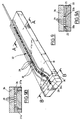
- Figure 2 is a sectional and elevational view of the lower part of a mechanism fixed on an adapter of the reactor vessel cover nuclear.
- Figure 3 is an enlarged sectional view of the lower part of the mechanism shown in the figure 2.
- FIG. 3A is an enlarged view of detail A of Figure 3.
- Figure 3B is a view along B of the figure 3A.
- Figures 4A and 4B are plan views of a support and displacement blade according to the invention and according to two variant embodiments.
- Figure 5 is a sectional view along 5-5 of Figure 4A or Figure 4B.
- Figure 6 is a sectional view along 6-6 of Figure 4A or Figure 4B.
- Figure 7 is a sectional view along 7-7 of Figure 4A or Figure 4B.
- Figure 8 is a plan view of part internal of the support blade shown in the figure 4A or in Figure 4B.
- Figure 9 is a perspective view of a mold open containing an insert, illustrating one of the phases of the manufacturing process by molding the blade support as shown in Figures 4A and 4B.
- Figures 9A and 9B are sectional views along A-A and B-B in Figure 9, respectively, showing the mold of Figure 9 closed by a cover.
- the mechanism comprises a tubular casing 2 of substantially cylindrical shape with the lower part has a thread 2a for fixing of the mechanism on the threaded upper part of a tank cover feedthrough adapter reactor, as shown in Figure 2.
- Mechanism 1 also has three coils electromagnetic actuators 3a, 3b and 3c allowing to move pieces of ferromagnetic material arranged in the inner bore of the housing 2.
- Ferromagnetic parts whose displacement is controlled by the windings 3a, 3b and 3c are shaped tubular and are mounted around a fixed part of the mechanism integral with the casing 2 in which is mounted sliding in the vertical direction a control rod 4 comprising a lower part 4a which comprises means for fixing an absorbent cluster constituting the control bar whose mechanism 1 ensures the displacement in the core of the nuclear reactor.
- the control rod 4 has a part 4b machined to present successive grooves, in the axial direction, delimiting between them teeth for the step-by-step movement of the control rod at which a control bar is attached.
- Moving the control bar, in the vertical direction, step by step, is provided by the assembly electromagnetic 3a constituting a lifting assembly of the control bar and two grabs 5a and 5b formed by a set of pawls which are controlled by the windings 3b and 3c to engage with the toothing 4b of the control rod 4 or to release the control rod.
- the pawls of the grapple 5a are fixed on a moving part which accompanies the control rod 4 during lifting it and which is returned to its initial position after an elementary displacement of the rod ordered.
- the grapple pawls 5b are pawls of support which maintain the control rod 4 and the cluster attached to this rod between two displacements one step of the control rod.
- the adapter 7 has, at its upper part, above the cover 6, a portion 8 diametrically widened having an external thread on which can be screwed the casing 2 of a movement mechanism 1 a command bar.
- a thermal cuff 9 comprising, at its lower part, a tulip 9a enabling re-engagement of the control rods in the corresponding adapters, when replacing the tank cover, after a nuclear reactor shutdown.
- the lower part of mechanism 1, which is shown in Figure 2 includes in particular the coil 3c for actuating the holding pawls and the assembly 5b of the retaining pawls.
- the axis vertical 10 In the bore of the casing 2 having for axis the axis vertical 10 is fixed, in a coaxial arrangement by relative to the casing, a tubular support 11 on which are pivotally mounted, via a horizontal axis pivot, the retaining pawls such as the pawl 12 shown in FIG. 3.
- Each set of ratchets has three ratchets arranged at 120 ° one of the other around axis 10.
- ferromagnetic parts are fixed or divers allowing control of each holding pawls, via a link 13 articulated at one of its ends on a ratchet and at its other end on a part 14 of tubular shape of the plunger of the retaining pawls.
- the part 14 of the retaining pawl is fixed by screwing on a second tubular part 15, in a coaxial arrangement.
- the second part 15 of the ratchet plunger of holding constitutes the pole piece of the plunger which is attracted by a fixed metal part 16, when feeds the magnetic winding 3c of the pawls maintenance.
- the diver is called back down by a spring 17 interposed between the fixed part 16 integral of the tubular support 11 and the pole piece 15 of the plunger retaining pawls.
- the part 14 is crossed by an opening in which a cup 19 is introduced and fixed by crimping metal sheet in which the head of the screw 18 which is screwed inside an opening tapped 20 crossing part of the part 15 coming facing the opening of the part 14 when we have carried out the assembly by screwing of parts 14 and 15.
- the screw 18 is made to rotate by deformation and crimping of two parts 19a and 19b of the cup 19 in two recesses of the head of the screw 18.
- the head of the screw 18 can come in protrusion inside the free space 21 formed between the outer surface of parts 14 and 15 of the plunger and the inner surface of the casing 2 of the mechanism 1. Because that the free space 21 has a small width in the radial direction, of the order of 3 mm, the screw head can come to rub against the surface inside of casing 2 of the mechanism, which can disturb or prevent the displacement of the pole pieces 14 and 15 actuating the retaining pawls 12.
- Such faulty operation is particularly undesirable when preventing a command bar to fall back into position of maximum insertion in the core of the nuclear reactor in the event of an emergency shutdown.
- This control can be carried out by optical examination, so as to control the position of the screw head 18 and check that this head is not protruding relative to the outer surface of the pieces of retaining pawl plungers 14 and 15.
- an optical examination means can only be done through the inside of the thermal cuff 9 of the adapter 7 on which the mechanism is fixed 1, after shutdown and cooling of the nuclear reactor and dismantling of the cover which is deposited on a support, in a room equipped with a handling arm allowing to introduce examination equipment inside the thermal cuffs of each of the bushing adapters of the cover, successively.
- the cover In this position allowing the control of adapters in particular, the cover is placed horizontally on the support, so that the adapters are arranged vertically.
- Tests have been carried out using camera elements attached to the end of a metal blade flat of a type already used to carry out the checking the internal surface of bushing adapters a tank cover using an inserted probe in the annular space between the thermal cuff and the adapter.
- Such a metal blade or saber has a thin between 1 and 2 mm and a width of the order of 10 to 15 mm.
- the length of the blade must be sufficient for the device to be sent optical examination in the area of the screw 18, from the lower part of the adapter thermal sleeve 9 constituted by the introductory tulip 9a.
- the optical examination device support saber To reach the annular space 21 from of the interior space of the thermal sleeve 9, the optical examination device support saber must be oriented towards a narrow passage 22 (Figure 3) formed between a peripheral part of the end bottom of part 14 of the ratchet plunger and part of the internal bore of the casing 2 of frustoconical shape placed between two parts with different diameters of this bore.
- the space 22 has a narrow width of around 1.6 mm.
- this passage 22 is located in an area device of the mechanism which is not level with the area with screw 18.
- the support blade of the optical examination device must therefore first be oriented in one direction inclined shown in Figure 3 to be introduced in passage 22 then must undergo a bending to penetrate in ring game 21 and finally a certain twist around axis 10 to reach the area of screw 18.
- a support blade has been produced and moving a new type, as shown in particular in Figures 4A and 4B.
- the blade 24 has a straight portion 24a of flat shape, the section of which is shown in the figure 6 and a curved portion 24b in the extension of the rectilinear part 24a which ends at the level of the head optical examination 24c carrying the optical elements 26 of the examination device fixed to the end of the blade 24.
- the 24c optical examination head also has two parts 27a and 27b thinner than the thickness of the blade and inclined with respect to the plane of the blade, of a same side of this plan.
- the blade 24 is connected to a section 28 section circular constituting the end of a connecting cable blade 24 and a set of signal processing optics provided by the elements 26.
- Optical signals are transmitted between the head optical examination comprising the optical elements 26 and the means of signal processing, by beams of optical fibers 29 arranged inside the blade 24 along its entire length.
- Each of the fiber bundles 29 can comprise a very large number of fibers, of the order of 10,000.
- the blade 24 is made completely monobloc in a thermoplastic material such as an elastomer.
- the fiber optic bundles 29 are completely embedded in the plastic material constituting the blade 24, so that the optical fibers are completely isolated from the outside environment and are not susceptible to come into contact with part of the mechanisms during the movement of the support blade between its operating position for examination of the screw 18 inside mechanisms and an outside withdrawal position of the mechanism. This avoids any deterioration fibers during the movement of the blade inside mechanisms.
- Slides 27a and 27b of the optical examination head 24c which constitute support and retaining springs of the blade inside the annular space 21 of the mechanism are also made in one piece with the body of the blade 24 of rectangular section.
- a blade of support having a thickness of the order of 1.4 mm, a width of 12 mm and a length from the end of the part 28 of the blade to the end of the head 24c optical examination, of the order of 500 mm.
- a polyurethane was preferably used for constitute the body of the blade 24 in which are embedded fiber optic bundles 29.
- Polyurethane has the advantage of having a high tensile strength, very high flexibility, low coefficient of friction on surfaces metallic, for example steel, less than 0.1, and high wear resistance when in contact rubbing with metal surfaces.
- the blades produced according to the invention having the dimensions mentioned above have resistance tensile strength of the order of 45 daN. We were able to realize and use blades according to the technique described having a resistance between 20 and 80 daN, which allows to avoid any risk of breaking the conditions of use for moving an examination device optics inside the annular space of mechanisms for moving control bars.
- plastics than polyurethane can be used to achieve the body of the blade and for example, silicones, polytetrafluoroethylene (Teflon), polyethylene or even polypropylene, to the extent that these plastics are acceptable as "usable products and materials nuclear power plant. "
- the optical devices 26 fixed at the end of the optical examination head 24c have elements optics for aiming in the axial direction to check that the screw head is not in projection in the annular space and optical elements radial sight to provide an image of the screw head and the crimp lock cup.
- the light signals recovered by the fibers of the bundles 29 in the area of the screw head which is lit up through a bundle of fibers are transmitted by optical fiber bundles arranged at inside and in the longitudinal direction of the body of the support and displacement blade 24 and at the inside of an optical cable extending the part end 28 of the blade. Signals get there to operating means making it possible to reconstruct an image of the screw head in axial sight and in sight radial.
- These means include in particular cameras CCD and a processing computer.
- the mechanical properties of the support blade and displacement as well as its geometric shape allow to facilitate the movement of this blade in the cramped and non-rectilinear space formed by the passage the blade at the bottom of the mechanisms and through the annular space between the plunger retaining pawls and the inner surface of the mechanism housing.
- the tensile strength of the blade polyurethane support which is of the order of 45 daN, in the case of the embodiment described, avoids risks of breakage of the blade inside a mechanism.
- Deflection and introduction of the blade into the access passage to the annular space of the mechanism are made by a device introduced inside the adapter thermal sleeve.
- the blade has in particular a core or insert consisting of fiber optic bundles 29 and means for holding these bundles of fibers in parallel arrangements in the longitudinal direction of the support blade.
- the nucleus or insert consisting of bundles of optical fibers (six bundles of parallel optical fibers have been shown in FIG. 8) and holding plates 30 bundles of optical fibers 29 grouped two by two, in parallel arrangements following the direction longitudinal of the blade.
- the plates 30 can be constituted by polyurethane wafers drilled so that present a network of openings 31 in which are engaged the fiber optic bundles 29 which are thus kept in parallel arrangements between them.
- At one end of the fiber bundles optics 29 are fixed optical means 26 allowing to pick up the optical signals which are then transmitted by the fibers of the bundles 29 to the processing means and image reconstruction.
- the fiber bundles 29 extend at the end of the blade opposite the optical examination head 24c comprising the optical means 26, inside a optical cable with circular section (see figure 7).
- the core or insert 32 of the blade made up of fiber bundles 29 and holding plates 30, inside the cavity of a mold 33.
- the insert 32 is shaped so as to have a curved part at the end of which are fixed the optical means 26 of the examination head 24c optic.
- the mold can be closed by a lid 34 coming to rest on the upper surface of the mold 33 in two parts support 33a and 33b of reduced surface.
- Lid 34 ensures the closing of the mold cavity in which insert 32 is inserted, in particular fiber bundles 29.
- the mold 33 comprises an insert 36 in which is machined a part of the mold cavity which is extended laterally by oblique cavities constituting the imprints molding 27'a and 27'b of springs 27a and 27b, as it is visible in Figure 9B.
- Channels 25 for recovering the polymerizable product in excess, during molding, are placed on the side and on the other side of the mold cavity.
- the implementation of the method has shown that the polyurethane is perfectly adherent on the fibers and on the spacers.
- the introduction of polyurethane in the openings 31 of the plates 30 as well as the coating of the fiber bundles 29 in the polyurethane allows to realize a very resistant bond between the plastic material of the blade and the elements which are fixed inside the blade.
- the realization in one piece of the blade and in particular, the realization in one piece of the blade and springs 27a, 27b avoid any risk an element of the blade comes off inside the mechanisms, during the optical examination.
- the elements of examination device entering the mechanisms are therefore totally captive. This captivity does not could be obtained only very difficult in the case of a metal blade.
- the plastic or elastomer blade molding in another way, for example by injecting the material hot plastic in a closed mold containing the insert. In all cases, the molding is carried out from so as to completely coat the fiber bundles optics and spacers in the blade in plastic or elastomer.
- the invention is not limited to the embodiment that has been described. This is how we can use materials other than polyurethane to achieve the blade body surrounding the fiber optic bundles.
- the spacing and holding plates conductors can be made of an identical material to the material constituting the body of the blade or a different material.
- the inserts arranged inside the mold forming the blade and which constitute, after molding, internal elements of the blade can have shapes and arrangements different from those which have been described.
- the invention applies to optical examinations of different objects of fixing screws of constituent parts of ratchet plungers of displacement mechanisms command bars.
- the blade of support and displacement according to the invention can be used to perform optical examinations or controls in many parts of a nuclear reactor or in other industrial installations with elements to be performed examination or control and accessible by passages cramped and not straight.
Landscapes
- Physics & Mathematics (AREA)
- General Physics & Mathematics (AREA)
- Optics & Photonics (AREA)
- Astronomy & Astrophysics (AREA)
- Monitoring And Testing Of Nuclear Reactors (AREA)
- Investigating Strength Of Materials By Application Of Mechanical Stress (AREA)
- Heating, Cooling, Or Curing Plastics Or The Like In General (AREA)
Description
L'invention concerne une lame de support et de déplacement d'un dispositif d'examen ou de contrôle dans un passage exigu et non rectiligne, un procédé de fabrication de la lame et son utilisation pour réaliser l'examen optique d'un élément d'un mécanisme de déplacement d'une barre de commande d'un réacteur nucléaire refroidi par de l'eau sous pression.The invention relates to a support blade and movement of an examination or control device in a cramped and non-straight passage, a manufacturing process of the slide and its use for carrying out the examination optics of an element of a displacement mechanism of a control rod of a cooled nuclear reactor by pressurized water.
Les réacteurs nucléaires refroidis par de l'eau sous pression comportent, à l'intérieur d'une cuve, un coeur constitué par des assemblages de combustible. Pour régler la réactivité du coeur, il est connu de déplacer, à l'intérieur de certains des assemblages du coeur, des grappes de crayons renfermant un matériau absorbant les neutrons, appelées barres de commande.Water-cooled nuclear reactors under pressure have, inside a tank, a core consisting of fuel assemblies. For regulate the reactivity of the heart, it is known to move, inside some of the heart assemblies, clusters of pencils containing absorbent material neutrons, called control rods.
Pour déplacer les barres de commande à l'intérieur du coeur, on utilise des mécanismes qui comportent des cliquets venant en prise avec des dents usinées avec un certain espacement suivant la longueur d'une tige de commande à laquelle est fixée la barre de commande.To move the control bars inside from the heart, we use mechanisms that include pawls engaging teeth machined with some spacing along the length of a rod command to which the command bar is attached.
Les barres de commande sont généralement introduites par la partie supérieure du coeur du réacteur nucléaire et les tiges de commande traversent le couvercle du réacteur à l'intérieur d'adaptateurs tubulaires qui comportent une extrémité supérieure à l'extérieur de la cuve sur laquelle est fixé le mécanisme de déplacement de la barre de commande.Control bars are usually introduced through the upper part of the reactor core nuclear and control rods pass through the cover the reactor inside tubular adapters which have an upper end outside of the tank on which the movement mechanism is fixed on the command bar.
Les mécanismes de barres de commande comportent des bobinages électromagnétiques permettant de déplacer la barre de commande et de manoeuvrer les cliquets pour les mettre en prise avec les dents de la tige de commande ou, au contraire, pour libérer la tige de commande, pendant les phases successives du déplacement de la barre de commande.Control bar mechanisms include electromagnetic coils for moving the command bar and maneuver the pawls to engage them with the teeth of the control rod or, on the contrary, to release the control rod, during the successive phases of the bar displacement control.
L'un des ensembles de cliquets venant en prise avec la barre de commande est monté sur un élément mobile dans la direction axiale à l'intérieur du carter renfermant les mécanismes.One of the sets of pawls engaging with the control bar mounted on a mobile element in the axial direction inside the housing containing the mechanisms.
Un second ensemble de cliquets est monté pivotant sur un élément monté fixe à l'intérieur du carter du mécanisme. Ce second ensemble de cliquets constitue un ensemble de maintien de la tige de commande en position dans la direction verticale, entre deux pas de déplacement de cette tige de commande.A second set of pawls is pivotally mounted on a fixed mounted element inside the casing of the mechanism. This second set of pawls constitutes a holding rod assembly in position in the vertical direction, between two displacement steps of this control rod.
Chacun des mécanismes comporte, autour d'un carter de forme sensiblement cylindrique, une première bobine électromagnétique assurant le déplacement de la barre de commande, une seconde bobine électromagnétique assurant la manoeuvre des cliquets fixés sur l'élément mobile et une troisième bobine de manoeuvre des cliquets montée en position fixe dans la direction axiale du mécanisme.Each of the mechanisms includes, around a casing of substantially cylindrical shape, a first electromagnetic coil ensuring the displacement of the control bar, a second electromagnetic coil ensuring the operation of the pawls fixed on the element mobile and a third pawl handling coil mounted in a fixed position in the axial direction of the mechanism.
Les bobines électromagnétiques du mécanisme assurent le déplacement, à l'intérieur de l'alésage du carter, d'éléments de forme annulaire appelé plongeur.The electromagnetic coils of the mechanism ensure the movement, inside the bore of the casing, of annular elements called plunger.
Les plongeurs sont déplacés vers le haut par attraction magnétique, lors de l'alimentation des bobinages correspondants et rappelés vers le bas par des ressorts et sous l'effet de la pesanteur.Divers are moved up by magnetic attraction, when feeding the windings corresponding and recalled downwards by springs and under the effect of gravity.
Les cliquets de l'ensemble de cliquets de maintien sont montés pivotants autour d'axes horizontaux sur une pièce tubulaire fixe montée dans une disposition coaxiale à l'intérieur du carter des mécanismes. Les cliquets sont manoeuvrés par l'intermédiaire de biellettes qui sont articulées chacune à l'une de leurs extrémités sur un cliquet et à leur autre extrémité sur un plongeur des cliquets de maintien. Par déplacement dans la direction verticale du plongeur, dans un sens ou dans l'autre, sous l'effet de l'attraction magnétique ou de la force de ressorts de rappel et de la pesanteur, chacun des cliquets de l'ensemble de cliquets de maintien peut être déplacé, par l'intermédiaire de la biellette correspondante, entre une position d'engagement sur la denture de la tige de commande et une position de retrait dans laquelle les cliquets de l'ensemble de maintien libèrent la tige de commande qui peut être déplacée alors dans la direction verticale.The pawls of the retaining pawl assembly are pivotally mounted around horizontal axes on a fixed tubular part mounted in an arrangement coaxial inside the mechanism housing. The pawls are operated by means of links which are each articulated at one of their ends on a ratchet and at their other end on a retaining pawl plunger. By moving in the vertical direction of the diver, in one direction or in the other, under the effect of magnetic attraction or force of return springs and gravity, each pawls the set of retaining pawls can be moved, via the corresponding link, between an engagement position on the teeth of the control rod and a withdrawal position in which the pawls of the holding assembly release the control rod which can then be moved in the vertical direction.
Pour permettre le montage du plongeur des cliquets de maintien à l'intérieur du carter du mécanisme, autour du support des cliquets de maintien solidaires du carter, le plongeur des cliquets de maintien est réalisé en deux parties de forme tubulaire qui sont raccordées bout à bout dans une disposition coaxiale par l'intermédiaire de deux extrémités d'assemblage qui sont vissées l'une sur l'autre et immobilisées l'une par rapport à l'autre, par l'intermédiaire d'une vis engagée dans des ouvertures alignées des deux parties du plongeur ayant une direction radiale par rapport aux pièces tubulaires constituant le plongeur.To allow mounting of the ratchet plunger holding inside the mechanism housing, around the support of the retaining pawls secured to the housing, the plunger of the holding pawls is made in two tubular parts which are connected end to end in a coaxial arrangement through of two assembly ends which are screwed one on the other and immobilized one with respect to the other, by means of a screw engaged in aligned openings of the two parts of the plunger having a radial direction with respect to the tubular parts constituting the diver.
La vis de blocage des deux parties du plongeur est immobilisée en rotation par déformation d'une coupelle sertie dans l'une des pièces, à l'intérieur d'embrèvements usinés dans la tête de la vis. La partie de la pièce recevant la tête de vis présente une surface externe placée en vis-à-vis de la surface interne du carter et séparée de celle-ci par un jeu faible de l'ordre de 3 mm.The locking screw of the two parts of the plunger is immobilized in rotation by deformation of a cup set in one of the pieces, inside of indents machined in the head of the screw. The part of the part receiving the screw head has an external surface placed opposite the internal surface of the housing and separated from it by a small clearance of the order of 3 mm.
Dans le cas de certains réacteurs nucléaires actuellement en fonctionnement, on a observé certains dysfonctionnements de mécanisme de barres de commande qui sont dus, au moins en partie, au desserrage de la vis de blocage des plongeurs de cliquets de maintien. En effet, dans certains cas, la vis de blocage a pu se desserrer, du fait d'un désertissage de sa tête engagée à l'intérieur de la partie du plongeur située en vis-à-vis de la surface intérieure du carter. Dans ce cas, la tête de vis vient en saillie par rapport à la surface extérieure de la pièce du plongeur et est susceptible, du fait du faible jeu existant entre la surface externe du plongeur et la surface intérieure du carter, de venir frotter contre cette surface intérieure.In the case of certain nuclear reactors currently in operation, some control rod mechanism malfunctions which are due, at least in part, to the loosening of the locking of the retaining pawl plungers. Indeed, in some cases, the locking screw may have come loose, due to a desertification of its head engaged inside of the part of the diver facing the inner surface of the housing. In this case, the screw head protrudes from the outer surface of part of the plunger and is susceptible, due to little clearance between the outer surface of the plunger and the inner surface of the housing, to rub against this interior surface.
Il est donc souhaitable de pouvoir contrôler périodiquement que la vis de blocage des plongeurs des cliquets de maintien des mécanismes de barres de commande d'un réacteur nucléaire ne se trouve pas en saillie par rapport à la surface du plongeur et présente une tête qui est correctement sertie à l'intérieur de la partie externe du plongeur.It is therefore desirable to be able to control periodically that the locking screw of the plungers of the control rod mechanisms holding pawls of a nuclear reactor is not protruding by relative to the surface of the diver and has a head which is correctly crimped inside the part external of the diver.
Ce contrôle, qui doit être effectué de préférence par examen optique, doit être réalisé sans démonter le mécanisme ; la zone où se trouve la vis de blocage n'est accessible que par l'intermédiaire de l'espace annulaire de faible largeur (cette largeur correspondant au jeu radial entre les plongeurs et la surface interne du carter du mécanisme) et d'une ouverture d'accès à cet espace annulaire débouchant, à l'une de ses extrémités, dans l'espace annulaire et, à son autre extrémité, à la partie inférieure du mécanisme.This check, which should preferably be carried out by optical examination, must be carried out without dismantling the mechanism; the area where the locking screw is located is not accessible only through the annular space narrow (this width corresponding to the clearance radial between the plungers and the internal surface of the mechanism housing) and an access opening to this annular space opening at one of its ends, in the annular space and, at its other end, at the lower part of the mechanism.
Pour faire parvenir un dispositif d'examen optique dans l'espace annulaire, au voisinage de la vis de blocage qui se trouve à une distance de l'ordre de 150 mm de la partie inférieure du carter du mécanisme, il est nécessaire de disposer d'un moyen de support et de déplacement du dispositif d'examen optique qui puisse être engagé dans un espace exigu (l'ouverture d'accès à l'espace annulaire du mécanisme présente une largeur de l'ordre de 1,6 mm) et déplacé suivant un parcours présentant un changement de direction.To send an optical examination device in the annular space, in the vicinity of the screw blockage which is at a distance of the order of 150 mm from the lower part of the mechanism housing, it is necessary to have a means of support and movement of the optical examination device which can be engaged in a confined space (the opening of access to the annular space of the mechanism has a width of about 1.6 mm) and moved along a course presenting a change of direction.
Une autre difficulté provient également du fait que la zone dans laquelle est située la vis de blocage ne se trouve pas dans l'alignement axial de l'ouverture d'accès. Another difficulty also stems from the fact that the area in which the locking screw is located does not is not in the axial alignment of the opening access.
Les adaptateurs de traversée du couvercle de la cuve d'un réacteur nucléaire à eau sous pression dans lesquels passe la tige de commande assurant le déplacement d'une barre de commande par l'intermédiaire d'un mécanisme comportent une chemise thermique placée à l'intérieur de l'adaptateur dans une disposition coaxiale, avec un faible jeu radial par rapport à la surface intérieure de l'adaptateur.The bushing adapters of the tank of a pressurized water nuclear reactor in which pass the control rod ensuring the movement a command bar via a mechanism have a thermal jacket placed at the inside of the adapter in a coaxial arrangement, with a small radial clearance compared to the surface inside the adapter.
Dans certains réacteurs nucléaires, on a observé une fissuration sur la surface intérieure des adaptateurs, en particulier dans leur zone de soudure avec le couvercle.In some nuclear reactors, we have observed cracking on the inner surface of the adapters, especially in their welding area with the lid.
Il s'est donc avéré nécessaire de concevoir des dispositifs permettant de réaliser l'examen de la surface intérieure de l'adaptateur. On a réalisé en particulier des dispositifs comportant une lame allongée de faible épaisseur et présentant une certaine souplesse à l'extrémité de laquelle on fixe un dispositif de contrôle, par exemple par ultrasons ou par courants de Foucault. Le dispositif de contrôle peut être déplacé à l'intérieur de l'espace annulaire entre la chemise thermique et la surface intérieure de l'adaptateur, par poussée et par traction sur la lame souple de grande longueur. Des dispositifs de rappel élastique permettent de plaquer la ou les sondes utilisées fixées à l'extrémité de la lame contre la surface intérieure de l'adaptateur.It therefore became necessary to design devices for performing surface examination inside the adapter. We realized in particular devices with an elongated blade of low thick and flexible at the end of which a control device is fixed, by example by ultrasound or eddy currents. The control device can be moved inside the annular space between the thermal jacket and the inner surface of the adapter, by pushing and by traction on the long flexible blade. Devices elastic return allow to press the or the probes used fixed at the end of the blade against the inner surface of the adapter.
Des conducteurs constitués par des fils ou des câbles de mesures fixés sur la lame ou sabre suivant sa direction longitudinale permettent d'alimenter les sondes et de recueillir les signaux de mesure par l'intermédiaire d'une partie d'extrémité de la lame restant à l'extérieur de l'adaptateur, après introduction et mise en position de la sonde dans l'espace annulaire de l'adaptateur. Conductors made up of wires or measurement cables fixed on the blade or saber according to its longitudinal direction supply the probes and collect the measurement signals via an end portion of the blade remaining at the outside of the adapter, after insertion and putting in position of the probe in the annular space of the adapter.
On a proposé d'utiliser des lames ou sabres constituées par des bandes plates métalliques ou des bandes stratifiées sur lesquelles sont fixés des conducteurs électriques suivant toute la longueur du sabre.It has been proposed to use blades or sabers made up by flat metallic bands or bands laminates on which conductors are fixed electric along the entire length of the saber.
On a essayé d'utiliser de telles lames ou sabres pour réaliser l'examen optique des vis d'assemblage des plongeurs de cliquets de maintien des mécanismes de déplacement des barres de commande d'un réacteur nucléaire.We tried to use such blades or sabers to carry out the optical examination of the assembly screws of the ratchet plungers holding the moving mechanisms nuclear reactor control rods.
Du fait, en particulier, de la faible largeur du passage d'entrée et de la présence d'un changement de direction sur le passage de la lame ou sabre, un blocage a tendance à se produire lorsque le dispositif d'examen fixé à l'extrémité du sabre parvient dans l'espace annulaire du mécanisme. Il peut être alors très difficile sinon impossible d'extraire le dispositif d'examen optique du passage annulaire, l'augmentation de la force de traction sur le sabre pouvant entraíner une rupture du sabre. Il est alors difficile sinon impossible de récupérer le dispositif d'examen optique et la partie d'extrémité du sabre introduite dans l'espace annulaire du mécanisme.Due, in particular, to the narrow width of the entry passage and the presence of a change of direction on the passage of the blade or saber, a blockage tends to occur when the examination device attached to the end of the saber reaches the annular space of the mechanism. Then it can be very difficult otherwise impossible to extract the optical examination device of the annular passage, increasing the force of pulling on the saber which can cause a rupture of the saber. It is then difficult if not impossible to recover the optical examination device and the end part of the saber introduced into the annular space of the mechanism.
En outre, lorsqu'un dispositif d'examen optique fixé à l'extrémité du sabre doit être relié à des moyens d'exploitation de signaux optiques et de reconstitution d'images, par l'intermédiaire de faisceaux de fibres optiques fixés suivant la direction longitudinale du sabre, dans le cas où les faisceaux sont fixés sur une des faces du sabre, les fibres constituant ces faisceaux peuvent venir en contact frottant avec certaines parties des mécanismes, pendant le déplacement du sabre pour la mise en place ou l'extraction du dispositif d'examen optique. Les fibres risquent d'être détériorées par usure ou par sectionnement, en particulier lorsqu'elles viennent en contact avec des arêtes vives des mécanismes. In addition, when an optical examination device attached to the end of the saber must be connected to means optical signal processing and reconstruction images, via fiber bundles optics fixed in the longitudinal direction of the saber, in the case where the beams are fixed on a of the saber faces, the fibers constituting these bundles can come into rubbing contact with certain parts mechanisms, during the movement of the saber for the placement or removal of the examination device optical. Fibers may be damaged by wear or by sectioning, especially when they come in contact with sharp edges of the mechanisms.
On connaít par les JP-A-62 033 813 et JP-A-02 019 129, des cathéters pour endoscopes utilisés pour l'examen de cavités dans le corps humain et pour effectuer certains traitements. Le cathéter comporte une pluralité de conducteurs pour l'alimentation de l'endoscope et la récupération de signaux, enrobés dans une matière plastique dont est constitué le cathéter. De tels cathéters ne sont pas adaptés à l'examen de pièces mécaniques difficilement accessibles.We know by JP-A-62 033 813 and JP-A-02 019 129, catheters for endoscopes used for examining cavities in the human body and for perform certain treatments. The catheter has a plurality of conductors for supplying the endoscope and signal recovery, embedded in a plastic material from which the catheter is made. Such catheters are not suitable for examining hardly accessible mechanical parts.
Le but de l'invention est donc de proposer une lame de support et de déplacement dans un passage exigu et non rectiligne, d'un dispositif d'examen ou de contrôle d'un élément d'une installation industrielle accessible par le passage exigu, fixé à l'une des extrémités longitudinales de la lame de support et relié, pour son alimentation et pour la récupération de signaux, à une pluralité de conducteurs disposés suivant la longueur de la lame, cette lame présentant des caractéristiques de souplesse et de résistance permettant d'éviter des blocages ou des ruptures lors de son déplacement dans le passage exigu et assurant une protection efficace des conducteurs disposés suivant sa longueur.The object of the invention is therefore to propose a support and displacement blade in a cramped passage and not rectilinear, of an examination or control device an element of an accessible industrial installation through the cramped passage, fixed at one end longitudinal of the support blade and connected, for its power supply and for signal recovery, at a plurality of conductors arranged along the length of the blade, this blade having characteristics of flexibility and resistance to avoid blockages or breaks during its movement in the passage cramped and ensuring effective protection of conductors arranged along its length.
Dans ce but, la lame de support et de déplacement suivant l'invention est constituée par une pièce monobloc en une matière plastique moulée, ayant une résistance à la traction comprise entre 20 et 80 daN et de préférence de l'ordre de 45 daN, ainsi qu'un coefficient de frottement sur l'acier inférieur à 0,1 et une forte résistance à l'usure dans le cas d'un frottement avec une surface métallique, les conducteurs reliés au dispositif de contrôle étant entièrement enrobés dans la matière plastique de la lame, sur toute la longueur de la lame. For this purpose, the support and displacement according to the invention is constituted by a one-piece molded plastic material having tensile strength between 20 and 80 daN and preferably of the order of 45 daN, as well as a coefficient of friction on steel less than 0.1 and high wear resistance in the case of a friction with a metal surface, the conductors connected to the control device being fully coated in the plastic of the blade, on all the length of the blade.
De préférence, la matière plastique moulée de la lame est un polyuréthanne.Preferably, the molded plastic of the blade is a polyurethane.
L'invention concerne également le procédé de réalisation par moulage de la lame de support et de déplacement.The invention also relates to the production method by molding the support and displacement blade.
L'invention est également relative à l'utilisation de la lame pour effectuer l'examen optique d'un élément disposé à l'intérieur d'un mécanisme de déplacement d'une barre de commande d'un réacteur nucléaire à eau sous pression et en particulier d'une vis de blocage de deux parties d'un plongeur du mécanisme.The invention also relates to the use of the blade to perform the optical examination of a element arranged inside a movement mechanism a nuclear reactor control bar at pressurized water and in particular a locking screw of two parts of a mechanism plunger.
Afin de bien faire comprendre l'invention, on va maintenant décrire à titre d'exemple non limitatif, en se référant aux figures jointes en annexe, une lame de support et de déplacement suivant l'invention, son procédé de fabrication et son utilisation pour réaliser un examen optique d'une vis de blocage de deux pièces d'un plongeur d'un mécanisme de déplacement d'une barre de commande d'un réacteur nucléaire à eau sous pression.In order to clearly understand the invention, we will now describe by way of nonlimiting example, by referring to the attached figures, a support blade and displacement according to the invention, its method and its use to perform an examination optics of a locking screw of two parts of a plunger a mechanism for moving a control bar of a pressurized water nuclear reactor.
La figure 1 est une vue en perspective éclatée d'un mécanisme de déplacement d'une barre de commande d'un réacteur nucléaire à eau sous pression.Figure 1 is an exploded perspective view a mechanism for moving a control bar of a pressurized water nuclear reactor.
La figure 2 est une vue en coupe et en élévation de la partie inférieure d'un mécanisme fixé sur un adaptateur de traversée du couvercle de cuve du réacteur nucléaire.Figure 2 is a sectional and elevational view of the lower part of a mechanism fixed on an adapter of the reactor vessel cover nuclear.
La figure 3 est une vue en coupe agrandie de la partie inférieure du mécanisme représenté sur la figure 2.Figure 3 is an enlarged sectional view of the lower part of the mechanism shown in the figure 2.
La figure 3A est une vue agrandie du détail A de la figure 3.FIG. 3A is an enlarged view of detail A of Figure 3.
La figure 3B est une vue suivant B de la figure 3A.Figure 3B is a view along B of the figure 3A.
Les figures 4A et 4B sont des vue en plan d'une lame de support et de déplacement suivant l'invention et suivant deux variantes de réalisation.Figures 4A and 4B are plan views of a support and displacement blade according to the invention and according to two variant embodiments.
La figure 5 est une vue en coupe suivant 5-5 de la figure 4A ou de la figure 4B.Figure 5 is a sectional view along 5-5 of Figure 4A or Figure 4B.
La figure 6 est une vue en coupe suivant 6-6 de la figure 4A ou de la figure 4B.Figure 6 is a sectional view along 6-6 of Figure 4A or Figure 4B.
La figure 7 est une vue en coupe suivant 7-7 de la figure 4A ou de la figure 4B.Figure 7 is a sectional view along 7-7 of Figure 4A or Figure 4B.
La figure 8 est une vue en plan d'une partie interne de la lame de support représentée sur la figure 4A ou sur la figure 4B.Figure 8 is a plan view of part internal of the support blade shown in the figure 4A or in Figure 4B.
La figure 9 est une vue en perspective d'un moule ouvert contenant un insert, illustrant l'une des phases du procédé de fabrication par moulage de la lame de support telle que représentée sur les figures 4A et 4B.Figure 9 is a perspective view of a mold open containing an insert, illustrating one of the phases of the manufacturing process by molding the blade support as shown in Figures 4A and 4B.
Les figures 9A et 9B sont des vues en coupe suivant A-A et B-B de la figure 9, respectivement, montrant le moule de la figure 9 fermé par un couvercle.Figures 9A and 9B are sectional views along A-A and B-B in Figure 9, respectively, showing the mold of Figure 9 closed by a cover.
Sur la figure 1, on voit un mécanisme de déplacement d'une barre de commande d'un réacteur nucléaire à eau sous pression désigné de manière générale par le repère 1.In Figure 1, we see a movement mechanism a nuclear reactor control bar at pressurized water generally designated by mark 1.
Le mécanisme comporte un carter tubulaire 2 de
forme sensiblement cylindrique dont la partie inférieure
présente un taraudage 2a permettant de réaliser la fixation
du mécanisme sur la partie supérieure filetée d'un
adaptateur de traversée du couvercle de la cuve du
réacteur, comme représenté sur la figure 2.The mechanism comprises a
Le mécanisme 1 comporte de plus trois bobines
électromagnétiques d'actionnement 3a, 3b et 3c permettant
de déplacer des pièces en matériau ferromagnétique disposées
dans l'alésage intérieur du carter 2.Mechanism 1 also has three coils
Les pièces ferromagnétiques dont le déplacement
est commandé par les bobinages 3a, 3b et 3c sont de forme
tubulaire et sont montées autour d'une partie fixe du
mécanisme solidaire du carter 2 dans laquelle est montée
glissante dans la direction verticale une tige de commande
4 comportant une partie inférieure 4a qui comporte
des moyens de fixation d'une grappe absorbante constituant
la barre de commande dont le mécanisme 1 assure le
déplacement dans le coeur du réacteur nucléaire.Ferromagnetic parts whose displacement
is controlled by the
La tige de commande 4 comporte une partie 4b
usinée pour présenter des gorges successives, dans la
direction axiale, délimitant entre elles des dents pour
le déplacement pas à pas de la tige de commande à laquelle
est fixée une barre de commande.The
Le déplacement de la barre de commande, dans la
direction verticale, pas par pas, est assuré par l'ensemble
électromagnétique 3a constituant un ensemble de levée
de la barre de commande et deux grappins 5a et 5b constitués
par un ensemble de cliquets qui sont commandés par
les bobinages 3b et 3c pour venir en prise avec la
denture 4b de la tige de commande 4 ou pour libérer la
tige de commande.Moving the control bar, in the
vertical direction, step by step, is provided by the assembly
electromagnetic 3a constituting a lifting assembly
of the control bar and two
Les cliquets du grappin 5a sont fixés sur une
pièce mobile qui accompagne la tige de commande 4 lors de
son levage et qui est rappelée dans sa position initiale
à l'issue d'un déplacement élémentaire de la tige de
commande.The pawls of the grapple 5a are fixed on a
moving part which accompanies the
Les cliquets du grappin 5b sont des cliquets de
maintien qui assurent le maintien de la tige de commande
4 et de la grappe fixée à cette tige entre deux déplacements
d'un pas de la tige de commande.The grapple
Sur la figure 2, on a représenté une partie du
couvercle 6 de la cuve d'un réacteur nucléaire dans
laquelle est fixé un tube de traversée 7 ou adaptateur
assurant le passage à l'intérieur de la cuve d'une tige
de commande telle que la tige 4 représentée sur la figure
1 et permettant le déplacement d'une grappe de commande
à l'intérieur d'un assemblage du coeur du réacteur
nucléaire disposé dans la cuve fermée par le couvercle 6.In Figure 2, part of the
L'adaptateur 7 comporte, à sa partie supérieure,
au-dessus du couvercle 6, une partie 8 élargie diamétralement
présentant un filetage externe sur lequel peut
être vissé le carter 2 d'un mécanisme 1 de déplacement
d'une barre de commande.The
A l'intérieur de l'adaptateur 7 est disposée une
manchette thermique 9 comportant, à sa partie inférieure,
une tulipe 9a permettant d'assurer un réengagement des
tiges de commande dans les adaptateurs correspondants,
lors d'une remise en place du couvercle de la cuve, après
un arrêt du réacteur nucléaire. Inside the
La partie inférieure du mécanisme 1, qui est
représentée sur la figure 2, comporte en particulier la
bobine 3c d'actionnement des cliquets de maintien et
l'ensemble 5b des cliquets de maintien.The lower part of mechanism 1, which is
shown in Figure 2, includes in particular the
Cette partie du mécanisme a été représentée plus en détail sur la figure 3.This part of the mechanism has been shown more in detail in Figure 3.
Dans l'alésage du carter 2 ayant pour axe l'axe
vertical 10 est fixé, dans une disposition coaxiale par
rapport au carter, un support tubulaire 11 sur lequel
sont montés pivotants, par l'intermédiaire d'un axe horizontal
de pivotement, les cliquets de maintien tels que
le cliquet 12 représenté sur la figure 3. Chaque jeu de
cliquets comporte trois cliquets disposés à 120° l'un de
l'autre autour de l'axe 10.In the bore of the
Autour du support tubulaire 11 et de l'ensemble
de cliquets de maintien, sont fixées des pièces ferromagnétiques
ou plongeurs permettant la commande de chacun
des cliquets de maintien, par l'intermédiaire d'une
biellette 13 articulée à l'une de ses extrémités sur un
cliquet et à son autre extrémité sur une pièce 14 de
forme tubulaire du plongeur des cliquets de maintien.Around the
La pièce 14 du cliquet de maintien est fixée par
vissage sur une seconde pièce tubulaire 15, dans une
disposition coaxiale.The
La seconde pièce 15 du plongeur de cliquets de
maintien constitue la pièce polaire du plongeur qui est
attirée par une pièce métallique fixe 16, lorsqu'on
alimente le bobinage magnétique 3c des cliquets de
maintien.The
De plus, le plongeur est rappelé vers le bas par
un ressort 17 intercalé entre la pièce fixe 16 solidaire
du support tubulaire 11 et la pièce polaire 15 du plongeur
des cliquets de maintien.In addition, the diver is called back down by
a
De manière à assurer une immobilisation des deux
pièces 14 et 15 du plongeur des cliquets de maintien, on
engage une vis de blocage 18 dans des ouvertures alignées
des pièces 14 et 15, après leur assemblage par vissage.In order to ensure immobilization of the two
Comme il est visible sur les figures 3A et 3B, la
pièce 14 est traversée par une ouverture dans laquelle
est introduite et fixée par sertissage une coupelle 19 en
tôle métallique dans laquelle est engagée la tête de la
vis 18 qui est vissée à l'intérieur d'une ouverture
taraudée 20 traversant une partie de la pièce 15 venant
en vis-à-vis de l'ouverture de la pièce 14 lorsqu'on a
réalisé l'assemblage par vissage des pièces 14 et 15.As can be seen in FIGS. 3A and 3B, the
On réalise le blocage en rotation de la vis 18
par déformation et sertissage de deux parties 19a et 19b
de la coupelle 19 dans deux embrèvements de la tête de la
vis 18.The
Bien que la vis 18 de blocage des deux parties 14
et 15 du plongeur des cliquets de maintien soit fixée par
sertissage de la coupelle, on a observé dans certains
cas, pendant le fonctionnement du réacteur nucléaire, un
dysfonctionnement du mécanisme ayant pour origine un
desserrage de la vis 18 qui peut être dû par exemple à un
mauvais sertissage de la coupelle 19 ou à une détérioration
de la coupelle 19 en service.Although the
Dans ce cas, la tête de la vis 18 peut venir en
saillie à l'intérieur de l'espace libre 21 ménagé entre
la surface extérieure des pièces 14 et 15 du plongeur et
la surface intérieure du carter 2 du mécanisme 1. Du fait
que l'espace libre 21 présente une faible largeur dans la
direction radiale, de l'ordre de 3 mm, la tête de vis
peut être amenée à venir frotter contre la surface
intérieure du carter 2 du mécanisme, ce qui peut perturber
ou empêcher le déplacement des pièces polaires 14 et
15 actionnant les cliquets de maintien 12.In this case, the head of the
Un tel fonctionnement défectueux est particulièrement indésirable lorsqu'il empêche une barre de commande de retomber en position d'insertion maximale dans le coeur du réacteur nucléaire en cas d'arrêt d'urgence.Such faulty operation is particularly undesirable when preventing a command bar to fall back into position of maximum insertion in the core of the nuclear reactor in the event of an emergency shutdown.
Il s'est donc avéré tout à fait souhaitable de
vérifier l'état de serrage et de sertissage des vis 18
d'assemblage des plongeurs des cliquets de maintien des
mécanismes de barres de commande des réacteurs nucléaires
à eau sous pression.It therefore proved to be entirely desirable to
check the tightening and crimping condition of the
Ce contrôle peut être réalisé par examen optique,
de manière à contrôler la position de la tête de la vis
18 et à vérifier que cette tête ne se trouve pas en saillie
par rapport à la surface extérieure des pièces de
plongeurs de cliquets de maintien 14 et 15.This control can be carried out by optical examination,
so as to control the position of the
Il est également souhaitable d'effectuer un contrôle du sertissage de la coupelle d'immobilisation de la tête de vis.It is also desirable to carry out a checking the crimping of the immobilization cup of the screw head.
Il est donc nécessaire de réaliser un examen optique
avec une visée dans la direction axiale du mécanisme,
au voisinage de la vis 18, pour voir si la tête de
vis ne se trouve pas en saillie par rapport à la surface
externe des pièces 14 et 15 et avec une visée radiale en
direction de la tête de vis 18 pour contrôler l'état de
sertissage de la coupelle 19, l'image optique étant analogue
à la vue de la figure 3B.It is therefore necessary to perform an optical examination
with a view in the axial direction of the mechanism,
in the vicinity of
Pour réaliser ces examens optiques au niveau de
la tête de la vis 18, dans l'espace annulaire 21, il est
nécessaire d'introduire un moyen d'éclairage et une
micro-caméra vidéo ou encore des éléments optiques de
captage d'images d'une caméra, dans le jeu 21, jusqu'au
niveau de la vis 18, c'est-à-dire à une distance de
l'ordre de 150 mm de la base du mécanisme.To carry out these optical examinations at the level of
the head of the
L'introduction d'un moyen d'examen optique ne
peut se faire que par l'intérieur de la manchette thermique
9 de l'adaptateur 7 sur lequel est fixé le mécanisme
1, après arrêt et refroidissement du réacteur nucléaire
et démontage du couvercle qui est déposé sur un support,
dans un local équipé d'un bras de manutention permettant
d'introduire un appareillage d'examen à l'intérieur des
manchettes thermiques de chacun des adaptateurs de traversée
du couvercle, successivement. Dans cette position
permettant le contrôle des adaptateurs en particulier, le
couvercle est placé horizontalement sur le support, de
sorte que les adaptateurs sont disposés verticalement.The introduction of an optical examination means
can only be done through the inside of the thermal cuff
9 of the
Des essais ont été réalisés en utilisant des éléments de caméra fixés à l'extrémité d'une lame métallique plate d'un type déjà utilisé pour réaliser le contrôle de la surface intérieure d'adaptateurs de traversée d'un couvercle de cuve à l'aide d'une sonde introduite dans l'espace annulaire entre la manchette thermique et l'adaptateur.Tests have been carried out using camera elements attached to the end of a metal blade flat of a type already used to carry out the checking the internal surface of bushing adapters a tank cover using an inserted probe in the annular space between the thermal cuff and the adapter.
Une telle lame métallique ou sabre présente une
faible épaisseur comprise entre 1 et 2 mm et une largeur
de l'ordre 10 à 15 mm. La longueur de la lame doit être
suffisante pour qu'on puisse faire parvenir le dispositif
d'examen optique dans la zone de la vis 18, depuis la
partie inférieure de la manchette thermique 9 de l'adaptateur
constituée par la tulipe d'introduction 9a.Such a metal blade or saber has a
thin between 1 and 2 mm and a width
of the order of 10 to 15 mm. The length of the blade must be
sufficient for the device to be sent
optical examination in the area of the
Pour parvenir dans l'espace annulaire 21 à partir
de l'espace intérieur de la manchette thermique 9, le
sabre de support du dispositif d'examen optique doit être
orienté en direction d'un passage 22 de faible largeur
(figure 3) ménagé entre une partie périphérique de l'extrémité
inférieure de la pièce 14 du plongeur de cliquet
de maintien et une partie de l'alésage intérieur du
carter 2 de forme tronconique placée entre deux parties
à diamètres différents de cet alésage.To reach the
L'espace 22 présente une largeur faible de
l'ordre de 1,6 mm.The
De plus, ce passage 22 se trouve dans une zone
périphérique du mécanisme qui n'est pas à l'aplomb de la
zone comportant la vis 18. In addition, this
La lame de support du dispositif d'examen optique
doit donc être tout d'abord orientée dans une direction
inclinée représentée sur la figure 3 pour être introduite
dans le passage 22 puis doit subir une flexion pour pénétrer
dans le jeu annulaire 21 et enfin un certain vrillage
autour de l'axe 10 pour parvenir dans la zone de la
vis 18.The support blade of the optical examination device
must therefore first be oriented in one direction
inclined shown in Figure 3 to be introduced
in
Lors des essais qui ont été effectués sur des
mécanismes de réacteur nucléaire à eau sous pression, il
s'est avéré que des lames ou sabres métalliques de la
technique connue ne pouvaient supporter les déformations
nécessaires pour parvenir jusque dans la zone de la vis
18 et qu'il se produisait des blocages ou même des ruptures
du ruban, soit lors de son introduction, soit lors
de son extraction. Il s'est donc avéré pratiquement
impossible d'utiliser des supports de sonde de contrôle
d'un type connu pour réaliser l'examen optique des vis de
fixation des plongeurs de cliquets de maintien des mécanismes
de réacteur nucléaire à eau sous pression.During tests which have been carried out on
pressurized water nuclear reactor mechanisms it
turned out that metal blades or sabers of the
known technique could not withstand the deformations
necessary to reach the area of the
Selon l'invention, on a réalisé une lame de support et de déplacement d'un type nouveau, tel que représenté en particulier sur les figures 4A et 4B.According to the invention, a support blade has been produced and moving a new type, as shown in particular in Figures 4A and 4B.
On ne décrira que la lame représentée sur la figure 4A, la lame représentée sur la figure 4B ne présentant qu'une légère différence de forme, comme il sera expliqué plus loin.We will only describe the blade shown on the Figure 4A, the blade shown in Figure 4B not having that a slight difference in shape, as it will explained further.
La lame de support et de déplacement désignée de
manière générale par le repère 24 sera décrite en se
référant aux figures 4A, 5, 6 et 7.The designated support and displacement blade of
generally by the
La lame 24 comporte une partie rectiligne 24a de
forme plate dont la section est représentée sur la figure
6 et une partie courbe 24b dans le prolongement de la
partie rectiligne 24a qui se termine au niveau de la tête
d'examen optique 24c portant les éléments optiques 26 du
dispositif d'examen fixé à l'extrémité de la lame 24. La
tête d'examen optique 24c comporte également deux parties
27a et 27b d'épaisseur plus faible que l'épaisseur de la
lame et inclinées par rapport au plan de la lame, d'un
même côté de ce plan.The
A l'extrémité opposée à la tête d'examen optique
24c, la lame 24 se raccorde à une partie 28 à section
circulaire constituant l'extrémité d'un câble de liaison
de la lame 24 et d'un ensemble d'exploitation des signaux
optiques fournis par les éléments 26.At the end opposite the optical examination head
24c, the
Les signaux optiques sont transmis entre la tête
d'examen optique comportant les éléments optiques 26 et
les moyens d'exploitation des signaux, par des faisceaux
de fibres optiques 29 disposés à l'intérieur de la lame
24 suivant toute sa longueur.Optical signals are transmitted between the head
optical examination comprising the
Chacun des faisceaux de fibres 29 peut comporter un nombre de fibres très important, de l'ordre de 10.000.Each of the fiber bundles 29 can comprise a very large number of fibers, of the order of 10,000.
La lame 24 est réalisée de manière totalement
monobloc en un matériau thermoplastique tel qu'un élastomère.The
Les faisceaux de fibres optiques 29 sont totalement
noyés dans la matière plastique constituant la lame
24, de telle sorte que les fibres optiques sont totalement
isolées du milieu extérieur et ne sont pas susceptibles
de venir en contact avec une partie des mécanismes
pendant le déplacement de la lame de support entre sa
position de service pour l'examen de la vis 18 à l'intérieur
des mécanismes et une position de retrait à l'extérieur
du mécanisme. On évite ainsi toute détérioration
des fibres pendant le déplacement de la lame à l'intérieur
des mécanismes.The fiber optic bundles 29 are completely
embedded in the plastic material constituting the
Les lames 27a et 27b de la tête d'examen optique
24c qui constituent des ressorts d'appui et de maintien
de la lame à l'intérieur de l'espace annulaire 21 du
mécanisme sont également réalisées en une seule pièce
avec le corps de la lame 24 à section rectangulaire.
Dans le cas de mécanismes de déplacement de barres
de commande de réacteurs nucléaires à eau sous pression
actuellement en service, on a utilisé une lame de
support ayant une épaisseur de l'ordre de 1,4 mm, une
largeur de 12 mm et une longueur depuis l'extrémité de la
partie 28 de la lame jusqu'à l'extrémité de la tête
d'examen optique 24c, de l'ordre de 500 mm.In the case of bar displacement mechanisms
for controlling pressurized water nuclear reactors
currently in use, a blade of
support having a thickness of the order of 1.4 mm, a
width of 12 mm and a length from the end of the
On a utilisé de préférence un polyuréthanne pour
constituer le corps de la lame 24 dans lequel sont noyés
les faisceaux de fibres optiques 29.A polyurethane was preferably used for
constitute the body of the
Le polyuréthanne présente l'avantage d'avoir une forte résistance à la traction, une très grande souplesse, un faible coefficient de frottement sur les surfaces métalliques, par exemple en acier, inférieur à 0,1, et une forte résistance à l'usure lorsqu'il est en contact frottant avec des surfaces métalliques.Polyurethane has the advantage of having a high tensile strength, very high flexibility, low coefficient of friction on surfaces metallic, for example steel, less than 0.1, and high wear resistance when in contact rubbing with metal surfaces.
Les lames réalisées selon l'invention présentant les dimensions mentionnées ci-dessus ont une résistance à la traction de l'ordre de 45 daN. On a pu réaliser et utiliser des lames suivant la technique décrite ayant une résistance comprise entre 20 et 80 daN, ce qui permet d'éviter tout risque de rupture dans les conditions d'utilisation pour le déplacement d'un dispositif d'examen optique à l'intérieur de l'espace annulaire de mécanismes de déplacement de barres de commande.The blades produced according to the invention having the dimensions mentioned above have resistance tensile strength of the order of 45 daN. We were able to realize and use blades according to the technique described having a resistance between 20 and 80 daN, which allows to avoid any risk of breaking the conditions of use for moving an examination device optics inside the annular space of mechanisms for moving control bars.
De plus, les fortes possibilités d'allongement de la lame (500 %) s'accompagnent d'un rétreint important permettant d'éviter tout risque de coincement dans le mécanisme de barre de commande.In addition, the strong possibilities of lengthening the blade (500%) is accompanied by a significant shrinkage to avoid any risk of jamming in the control bar mechanism.
Bien entendu, d'autres matières plastiques que le polyuréthanne peuvent être utilisées pour réaliser le corps de la lame et par exemple, les silicones, le polytétrafluoréthylène (Téflon), le polyéthylène ou encore le polypropylène, dans la mesure où ces matières plastiques sont acceptables comme "produits et matériaux utilisables en centrale nucléaire".Of course, other plastics than polyurethane can be used to achieve the body of the blade and for example, silicones, polytetrafluoroethylene (Teflon), polyethylene or even polypropylene, to the extent that these plastics are acceptable as "usable products and materials nuclear power plant. "
Pour effectuer la mise en place d'un dispositif
d'examen optique à l'intérieur de l'espace annulaire des
mécanismes, au niveau de la vis 18, on a utilisé des
lames de support présentant une partie courbe d'extrémité
24b dirigée à gauche, comme représenté sur la figure 4A,
ou présentant une partie courbe dirigée à droite, comme
représenté sur la figure 4B, suivant la disposition relative
du passage 22 de la partie inférieure des mécanismes
et de la vis 18, à la périphérie des mécanismes.To set up a device
optical examination inside the annular space of
mechanisms, at the level of
La présence d'une partie courbe permet d'éviter
d'avoir à effectuer un vrillage hélicoïdal de la lame
dans l'espace annulaire des mécanismes, pour parvenir à
la vis 18.The presence of a curved part avoids
to have to make a helical twist of the blade
in the annular space of the mechanisms, to achieve
Les dispositifs optiques 26 fixés à l'extrémité
de la tête d'examen optique 24c comportent des éléments
optiques permettant une visée dans la direction axiale
pour contrôler que la tête de vis ne se trouve pas en
saillie dans l'espace annulaire et des éléments optiques
de visée radiale pour fournir une image de la tête de vis
et de la coupelle de blocage par sertissage.The
Les signaux lumineux récupérés par les fibres des
faisceaux 29 dans la zone de la tête de vis qui est
éclairée par l'intermédiaire d'un faisceau de fibres sont
transmis par des faisceaux de fibres optiques disposés à
l'intérieur et suivant la direction longitudinale du
corps de la lame de support et de déplacement 24 et à
l'intérieur d'un câble optique prolongeant la partie
d'extrémité 28 de la lame. Les signaux parviennent ainsi
à des moyens d'exploitation permettant de reconstituer
une image de la tête de vis en visée axiale et en visée
radiale. Ces moyens comportent en particulier des caméras
CCD et un ordinateur de traitement. The light signals recovered by the fibers of the
Les propriétés mécaniques de la lame de support et de déplacement ainsi que sa forme géométrique permettent de faciliter le déplacement de cette lame dans l'espace exigu et non rectiligne constitué par le passage d'introduction de la lame à la partie inférieure des mécanismes et par l'espace annulaire entre le plongeur des cliquets de maintien et la surface intérieure du carter du mécanisme.The mechanical properties of the support blade and displacement as well as its geometric shape allow to facilitate the movement of this blade in the cramped and non-rectilinear space formed by the passage the blade at the bottom of the mechanisms and through the annular space between the plunger retaining pawls and the inner surface of the mechanism housing.
Le faible coefficient de frottement de la lame en
polyuréthanne sur l'acier, ce coefficient étant inférieur
à 0,1, ainsi que les fortes possibilités d'allongement de
la lame (500 %) permettent de faciliter l'introduction et
le déplacement de la lame dans l'espace exigu et non rectiligne
du mécanisme. L'allongement, le rétreint et le
comportement élastique de la lame permettent d'autre part
un dégagement de cette lame, en cas de coincement dans
une partie de l'espace exigu non rectiligne d'accès à la
vis 18. D'autre part, la lame présente une bonne rigidité
longitudinale.The low coefficient of friction of the blade in
polyurethane on steel, this coefficient being lower
to 0.1, as well as the strong possibilities of lengthening
the blade (500%) makes it easier to introduce and
displacement of the blade in the confined and non-rectilinear space
of the mechanism. Elongation, constriction and
elastic behavior of the blade allow on the other hand
a release of this blade, in case of jamming in
part of the confined non-rectilinear space to access the
En outre, la résistance à la traction de la lame de support en polyuréthanne qui est de l'ordre de 45 daN, dans le cas du mode de réalisation décrit, permet d'éviter des risques de rupture de la lame à l'intérieur d'un mécanisme.In addition, the tensile strength of the blade polyurethane support which is of the order of 45 daN, in the case of the embodiment described, avoids risks of breakage of the blade inside a mechanism.
La déflexion et l'introduction de la lame dans le passage d'accès à l'espace annulaire du mécanisme sont réalisées par un dispositif introduit à l'intérieur de la manchette thermique de l'adaptateur.Deflection and introduction of the blade into the access passage to the annular space of the mechanism are made by a device introduced inside the adapter thermal sleeve.
Ce dispositif fait l'objet d'une demande de brevet déposée le même jour que la présente demande.This device is the subject of a request for patent filed on the same day as this application.
On va maintenant décrire, en se référant aux figures 8 et 9, un procédé de réalisation de la lame de support et de déplacement selon l'invention en utilisant un procédé de moulage d'une matière plastique. We will now describe, with reference to Figures 8 and 9, a method of producing the blade support and displacement according to the invention using a process for molding a plastic material.
La lame comporte en particulier un noyau ou insert constitué par les faisceaux de fibres optiques 29 et des moyens de maintien de ces faisceaux de fibres dans des dispositions parallèles suivant la direction longitudinale de la lame de support.The blade has in particular a core or insert consisting of fiber optic bundles 29 and means for holding these bundles of fibers in parallel arrangements in the longitudinal direction of the support blade.
Sur la figure 8, on a représenté le noyau ou
insert constitué par des faisceaux de fibres optiques
(six faisceaux de fibres optiques parallèles ont été représentés
sur la figure 8) et des plaquettes 30 de maintien
des faisceaux de fibres optiques 29 groupés deux par
deux, dans des dispositions parallèles suivant la direction
longitudinale de la lame.In FIG. 8, the nucleus or
insert consisting of bundles of optical fibers
(six bundles of parallel optical fibers have been shown
in FIG. 8) and holding
Les plaquettes 30 peuvent être constituées par
des plaquettes de polyuréthanne percées de manière à
présenter un réseau d'ouvertures 31 dans lesquelles sont
engagés les faisceaux de fibres optiques 29 qui sont
ainsi maintenus dans des dispositions parallèles entre
eux.The
A l'une des extrémités des faisceaux de fibres
optiques 29 sont fixés des moyens optiques 26 permettant
de capter les signaux optiques qui sont ensuite transmis
par les fibres des faisceaux 29 aux moyens de traitement
et de reconstitution d'images.At one end of the
Les faisceaux de fibres 29 se prolongent, à l'extrémité de la lame opposée à la tête d'examen optique 24c comportant les moyens optiques 26, à l'intérieur d'un câble optique à section circulaire (voir figure 7).The fiber bundles 29 extend at the end of the blade opposite the optical examination head 24c comprising the optical means 26, inside a optical cable with circular section (see figure 7).
Comme il est visible sur la figure 9, pour réaliser
par moulage une lame de support et de déplacement
suivant l'invention, on place le noyau ou insert 32 de la
lame constitué par les faisceaux de fibres 29 et les
plaquettes de maintien 30, à l'intérieur de la cavité
d'un moule 33. L'insert 32 est mis en forme de manière à
présenter une partie courbe à l'extrémité de laquelle
sont fixés les moyens optiques 26 de la tête d'examen
optique 24c.As shown in Figure 9, to achieve
by molding a support and displacement blade
according to the invention, the core or insert 32 of the
blade made up of
Comme il est visible sur les figures 9A et 9B, le
moule peut être fermé par un couvercle 34 venant reposer
sur la surface supérieure du moule 33 suivant deux parties
d'appui 33a et 33b de surface réduite. Le couvercle
34 assure la fermeture de la cavité du moule dans laquelle
est introduit l'insert 32 comportant en particulier
les faisceaux de fibres 29.As can be seen in FIGS. 9A and 9B, the
mold can be closed by a
A l'une de ses extrémités, le moule 33 comporte
une pièce rapportée 36 dans laquelle est usinée une
partie de la cavité du moule qui est prolongée latéralement
par des cavités obliques constituant les empreintes
de moulage 27'a et 27'b des ressorts 27a et 27b, comme il
est visible sur la figure 9B.At one of its ends, the
Des canaux 25 de récupération du produit polymérisable
en excès, pendant le moulage, sont placés de part
et d'autre de la cavité du moule.
Il est possible de remplir la cavité du moule de
manière à entourer complètement l'insert par une préparation
polymérisable qui est ensuite polymérisée pour
réaliser une lame d'une matière souple entourant complètement
l'insert. Pour cela, on réalise le préchauffage du
moule 33 et du couvercle 34 ainsi que du produit polymérisable,
en les plaçant dans une étuve à une température
de 30 à 35°C. Ensuite, on remplit le moule de matière
polymérisable et on referme le couvercle 34. Le moule
renfermant la matière polymérisable et fermé par son
couvercle est placé dans une étuve, à une température de
35 à 40°C, pour une durée d'environ 24 heures.It is possible to fill the mold cavity with
so as to completely surround the insert with a preparation
polymerizable which is then polymerized to
make a blade of a flexible material completely surrounding
the insert. For this, the preheating of the
Après remplissage du moule et au moment de la
fermeture du couvercle, du produit polymérisable en excès
dans la cavité du moule est chassé latéralement sur les
parties d'appui 33a et 33b de la surface supérieure du
moule 33 pour être évacué par les canaux 25. After filling the mold and at the time of
closing the lid, excess polymerizable product
in the mold cavity is driven laterally on the
Le maintien de la matière polymérisable à une
température de 35 à 40°C, à l'intérieur de la cavité du
moule permet de réaliser la polymérisation et le durcissement
de la matière polymérisable. On obtient ainsi une
lame de polyuréthanne dans laquelle sont noyés les
faisceaux de fibres optiques 29 et les plaquettes d'espacement
30.Maintaining the polymerizable material at a
temperature from 35 to 40 ° C, inside the cavity of the
mold allows polymerization and hardening
polymerizable material. We thus obtain a
polyurethane strip in which the
fiber optic bundles 29 and
La mise en oeuvre du procédé a montré que le
polyuréthanne est parfaitement adhérent sur les fibres et
sur les plaquettes d'espacement. L'introduction de
polyuréthanne dans les ouvertures 31 des plaquettes 30
ainsi que l'enrobage des faisceaux de fibres 29 dans le
polyuréthanne permet de réaliser une liaison très résistante
entre la matière plastique de la lame et les
éléments qui sont fixés à l'intérieur de la lame. En
outre, la réalisation sous forme monobloc de la lame et
en particulier, la réalisation en une seule pièce de la
lame et des ressorts 27a, 27b permet d'éviter tout risque
qu'un élément de la lame ne se détache à l'intérieur des
mécanismes, pendant l'examen optique. Les éléments du
dispositif d'examen pénétrant dans les mécanismes sont
donc totalement imperdables. Cette imperdabilité ne
pourrait être obtenue que très difficilement dans le cas
d'une lame en métal.The implementation of the method has shown that the
polyurethane is perfectly adherent on the fibers and
on the spacers. The introduction of
polyurethane in the
Bien entendu, il serait possible de réaliser le moulage de la lame en matière plastique ou élastomère d'une autre manière, par exemple en injectant la matière plastique à chaud dans un moule fermé renfermant l'insert. Dans tous les cas, le moulage est réalisé de manière à enrober totalement les faisceaux de fibres optiques et les plaquettes d'espacement dans la lame en matière plastique ou élastomère.Of course, it would be possible to carry out the plastic or elastomer blade molding in another way, for example by injecting the material hot plastic in a closed mold containing the insert. In all cases, the molding is carried out from so as to completely coat the fiber bundles optics and spacers in the blade in plastic or elastomer.
L'invention ne se limite pas au mode de réalisation qui a été décrit. C'est ainsi qu'on peut utiliser d'autres matières que le polyuréthanne pour réaliser le corps de la lame entourant les faisceaux de fibres optiques.The invention is not limited to the embodiment that has been described. This is how we can use materials other than polyurethane to achieve the blade body surrounding the fiber optic bundles.
Les plaquettes d'espacement et de maintien des conducteurs peuvent être réalisées en une matière identique à la matière constituant le corps de la lame ou en une matière différente.The spacing and holding plates conductors can be made of an identical material to the material constituting the body of the blade or a different material.
Les inserts disposés à l'intérieur du moule de formage de la lame et qui constituent, après moulage, des éléments internes de la lame peuvent avoir des formes et des agencements différents de ceux qui ont été décrits.The inserts arranged inside the mold forming the blade and which constitute, after molding, internal elements of the blade can have shapes and arrangements different from those which have been described.
On peut donner toute forme et toutes dimensions à la lame, de manière à faciliter l'accès d'un dispositif d'examen fixé à l'extrémité de cette lame dans une zone d'examen située dans un passage exigu et non rectiligne.We can give any shape and any size to the blade, so as to facilitate the access of a device examination attached to the end of this blade in an area of examination located in a cramped and not rectilinear passage.
L'invention s'applique à des examens optiques d'objets différents de vis de fixation de pièces constitutives de plongeurs de cliquets de mécanismes de déplacement de barres de commande. En particulier, la lame de support et de déplacement suivant l'invention peut être utilisée pour effectuer des examens optiques ou des contrôles dans de nombreuses parties d'un réacteur nucléaire ou encore dans d'autres installations industrielles comportant des éléments dont on doit effectuer l'examen ou le contrôle et accessibles par des passages exigus et non rectilignes.The invention applies to optical examinations of different objects of fixing screws of constituent parts of ratchet plungers of displacement mechanisms command bars. In particular, the blade of support and displacement according to the invention can be used to perform optical examinations or controls in many parts of a nuclear reactor or in other industrial installations with elements to be performed examination or control and accessible by passages cramped and not straight.
Claims (13)
- Movable member for supporting in a narrow passage (21) which is not straight, a device (26) for examining and inspecting a part of an industrial installation accessible through the narrow passage (21), fixed to one of the longitudinal ends of the supporting part (24) and connected, to supply it and recover signals, to a number of conductors (29), arranged to suit the length of the member (24), characterised in that it consists of a one-piece part made from a moulded plastic material, having a tensile strength between 20 and 80 daN and preferably in the region of 45 daN, as well as a coefficient of friction on steel below 0.1 and a high resistance to wear in the case of rubbing on a metal surface, the conductors (29) connected to the examining or inspecting device (26) being entirely wrapped in the plastic material of the member (24) over the full length of the member (24).
- Movable support member according to Claim 1, characterised in that the conductors (29) consist of fibre optic bundles and that the examining device (26) is an optical examination device.
- Support member according to any one of the claims 1 and 2, characterised in that the polymer material of the member (24) is polyurethane.
- Support member according to any one of the Claims 1 to 3, characterised in that it has at one of its ends an optical examination or inspection head which takes optical examination parts (26) or inspection parts and has lateral extensions (27a, 27b) made integral with the support member and at an angle to the faces of the member (24), consisting of springs for holding the optical examination or inspection head (24c) in the narrow passage (21).
- Support member according to any one of the Claims 1 to 4, characterised in that it has in succession, along its length, a straight section (24a) and a curved section (24b) to the end of which the examination or inspection device (26) is fixed.
- Support member according to Claim 5, characterised in that the conductors (29) are arranged, in the extension of the member (24) as from the end of the member opposite to the end taking the examination or inspection device, inside a cable with a circular section.
- Process for manufacturing a movable support member according to any one of the Claims 1 to 6, characterised in that:a core or insert is made consisting of conductors (29) fitted into more or less parallel arrangements,the core or insert (32) is placed in a mould (33) which has a cavity in the shape of the support member to be made, anda plastic material is moulded in the mould around the core or insert.
- Process according to Claim 7, characterised in that the mould is filled with a polymerisable material and that material is polymezised inside the mould.
- Process according to Claim 8, characterised in that the mould (33), brought to a temperature of 30 to 35°C is filled with a polymerisable preparation intended to form a polyurethane, at a temperature of 30 to 35°, and that the polymerisable material is polymerised inside the mould at a temperature between 35 and 40° inclusive.
- Process according to any one of the Claims 7 to 9, characterised in that the core or insert has spacer plates (30) with a series of apenings (31) in which the conductors (29) are engaged in parallel arrangements, the spacer plates (30) being spaced from each other in the longitudinal direction of the conductors (29).
- Process according to Claim 10, characterised in that the spacer plates (30) are from a plastic material identical with the material of the one-piece part of the movable support member (24).
- Application of a movable support member according to any one of the Claims 1 to 6 to perform an optical examination of an element (18) inside a casing (2) of a mechanism (1) for moving a control rod of a pressurised water nuclear reactor.
- Application according to Claim 12, characterised in that the element (18) is a screw for assembling two parts (14, 15) of a pawl plunger for holding the mechanism (1) activated by an electromagnetic coil (3c).
Applications Claiming Priority (2)
| Application Number | Priority Date | Filing Date | Title |
|---|---|---|---|
| FR9613273 | 1996-10-30 | ||
| FR9613273A FR2755229B1 (en) | 1996-10-30 | 1996-10-30 | SUPPORTING AND MOVING BLADE OF AN EXAMINATION OR CONTROL DEVICE, METHOD OF MANUFACTURING THE BLADE AND ITS USE |
Publications (2)
| Publication Number | Publication Date |
|---|---|
| EP0840097A1 EP0840097A1 (en) | 1998-05-06 |
| EP0840097B1 true EP0840097B1 (en) | 2002-09-11 |
Family
ID=9497191
Family Applications (1)
| Application Number | Title | Priority Date | Filing Date |
|---|---|---|---|
| EP19970402462 Expired - Lifetime EP0840097B1 (en) | 1996-10-30 | 1997-10-17 | Movable support member for an examining or controlling device, method for its manufacture and use thereof |
Country Status (3)
| Country | Link |
|---|---|
| EP (1) | EP0840097B1 (en) |
| ES (1) | ES2183104T3 (en) |
| FR (1) | FR2755229B1 (en) |
Family Cites Families (6)
| Publication number | Priority date | Publication date | Assignee | Title |
|---|---|---|---|---|
| JPS59143105A (en) * | 1983-02-04 | 1984-08-16 | Furukawa Electric Co Ltd:The | Optical fiber array and its production |
| US5192278A (en) * | 1985-03-22 | 1993-03-09 | Massachusetts Institute Of Technology | Multi-fiber plug for a laser catheter |
| JPS6239813A (en) * | 1985-08-15 | 1987-02-20 | Sumitomo Electric Ind Ltd | Endoscope catheter |
| JPH0219129A (en) * | 1988-07-08 | 1990-01-23 | Toshiba Corp | Endoscope |
| DE3936007A1 (en) * | 1989-10-28 | 1991-05-02 | Rheydt Kabelwerk Ag | OPTICAL CABLE |
| JPH0651141A (en) * | 1992-07-31 | 1994-02-25 | Mitsubishi Rayon Co Ltd | Manufacturing method of plastic multi-filament type optical fiber and optical fiber for endoscope using the same |
-
1996
- 1996-10-30 FR FR9613273A patent/FR2755229B1/en not_active Expired - Fee Related
-
1997
- 1997-10-17 EP EP19970402462 patent/EP0840097B1/en not_active Expired - Lifetime
- 1997-10-17 ES ES97402462T patent/ES2183104T3/en not_active Expired - Lifetime
Also Published As
| Publication number | Publication date |
|---|---|
| FR2755229A1 (en) | 1998-04-30 |
| ES2183104T3 (en) | 2003-03-16 |
| EP0840097A1 (en) | 1998-05-06 |
| FR2755229B1 (en) | 1999-01-15 |
Similar Documents
| Publication | Publication Date | Title |
|---|---|---|
| EP0753861B1 (en) | Arrangement for automatically decoupling a drive rod and an absorber assembly of a nuclear reactor | |
| CA1306522C (en) | Shape memory element for a connector braid connection | |
| EP0346170A1 (en) | Device for measuring parameters in the core of a nuclear reactor in operation | |
| FR2733005A1 (en) | LOGGING CABLE | |
| EP0399863A1 (en) | Device for the introduction and the positioning of a tool into a pipe of a steam generator and use of that device | |
| EP0840097B1 (en) | Movable support member for an examining or controlling device, method for its manufacture and use thereof | |
| BE897757A (en) | GRIPPING DEVICE FOR SIMULTANEOUSLY REMOVING A MULTIPLICITY OF FUEL BARS FROM A NUCLEAR FUEL ASSEMBLY | |
| FR2526532A1 (en) | APPARATUS FOR CHECKING THE TUBES OF A HEAT EXCHANGER AT A DISTANCE GIVEN FROM THE END OF THESE TUBES | |
| EP1395377A1 (en) | Device for assembling by crimping linking components on means to be assembled | |
| CA2343596C (en) | Electronic connection device, and power distribution apparatus containing said device | |
| FR2672423A1 (en) | Device for manufacturing composite insulators for overhead power lines | |
| EP0275773B1 (en) | Wiring installation for connecting electric devices associated with a nuclear reactor | |
| EP0123607A1 (en) | Hold-down apparatus for a nuclear reactor | |
| FR2491220A1 (en) | OPTICAL CABLE COMPRISING AT LEAST ONE ELEMENT COMPRISING AT LEAST ONE OPTICAL FIBER COATED IN A SHEATH OF PLASTIC MATERIAL, THE ELEMENT OR SET OF ELEMENTS BEING MAINTAINED WITHIN A METAL PROTECTIVE TUBE | |
| EP2478524A1 (en) | Device for assisting in the underwater extraction or insertion of an elongate element disposed in a pipe, and method for assisting in the extraction or insertion of one such element | |
| FR2749435A1 (en) | DEVICE FOR DECOUPLING A CONTROL ROD OF AN ABSORBENT ELEMENT FOR A NUCLEAR REACTOR | |
| EP0208596A1 (en) | Vibration damper for a towed element | |
| FR2976993A1 (en) | SPRING DEVICE | |
| EP0285464B1 (en) | Heating device, in particular for heat-treating small diameter bent tubes, and the use of said device | |
| EP0449736B1 (en) | Thermal buckler | |
| EP0077245B1 (en) | Manipulator for remote intervention in a water collector of a steam generator | |
| FR2596859A1 (en) | DEVICE FOR REMOTE MEASUREMENT OF THE OUTSIDE DIAMETER OF A CYLINDRICAL SHAPE ELEMENT PROJECTING RELATIVE TO THE SURFACE OF A PLATE | |
| FR2755239A1 (en) | Optical examination of component inside PWR control rod drive mechanism | |
| FR2598247A1 (en) | CORE PLUG OF A FAST NEUTRAL NUCLEAR REACTOR | |
| BE1007333A3 (en) | Device and method for straightening guide vane-grid spacers for fuel assembly of a nuclear reactor. |
Legal Events
| Date | Code | Title | Description |
|---|---|---|---|
| PUAI | Public reference made under article 153(3) epc to a published international application that has entered the european phase |
Free format text: ORIGINAL CODE: 0009012 |
|
| AK | Designated contracting states |
Kind code of ref document: A1 Designated state(s): BE CH ES LI SE |
|
| AX | Request for extension of the european patent |
Free format text: AL;LT;LV;RO;SI |
|
| 17P | Request for examination filed |
Effective date: 19980404 |
|
| AKX | Designation fees paid |
Free format text: BE CH ES LI SE |
|
| RBV | Designated contracting states (corrected) |
Designated state(s): BE CH ES LI SE |
|
| REG | Reference to a national code |
Ref country code: DE Ref legal event code: 8566 |
|
| 17Q | First examination report despatched |
Effective date: 20010521 |
|
| GRAG | Despatch of communication of intention to grant |
Free format text: ORIGINAL CODE: EPIDOS AGRA |
|
| GRAG | Despatch of communication of intention to grant |
Free format text: ORIGINAL CODE: EPIDOS AGRA |
|
| GRAH | Despatch of communication of intention to grant a patent |
Free format text: ORIGINAL CODE: EPIDOS IGRA |
|
| GRAH | Despatch of communication of intention to grant a patent |
Free format text: ORIGINAL CODE: EPIDOS IGRA |
|
| GRAA | (expected) grant |
Free format text: ORIGINAL CODE: 0009210 |
|
| AK | Designated contracting states |
Kind code of ref document: B1 Designated state(s): BE CH ES LI SE |
|
| REG | Reference to a national code |
Ref country code: CH Ref legal event code: EP |
|
| RAP2 | Party data changed (patent owner data changed or rights of a patent transferred) |
Owner name: FRAMATOME ANP |
|
| REG | Reference to a national code |
Ref country code: ES Ref legal event code: FG2A Ref document number: 2183104 Country of ref document: ES Kind code of ref document: T3 |
|
| PLBE | No opposition filed within time limit |
Free format text: ORIGINAL CODE: 0009261 |
|
| STAA | Information on the status of an ep patent application or granted ep patent |
Free format text: STATUS: NO OPPOSITION FILED WITHIN TIME LIMIT |
|
| 26N | No opposition filed |
Effective date: 20030612 |
|
| PGFP | Annual fee paid to national office [announced via postgrant information from national office to epo] |
Ref country code: SE Payment date: 20031021 Year of fee payment: 7 |
|
| PGFP | Annual fee paid to national office [announced via postgrant information from national office to epo] |
Ref country code: CH Payment date: 20031022 Year of fee payment: 7 |
|
| PGFP | Annual fee paid to national office [announced via postgrant information from national office to epo] |
Ref country code: ES Payment date: 20031107 Year of fee payment: 7 |
|
| PGFP | Annual fee paid to national office [announced via postgrant information from national office to epo] |
Ref country code: BE Payment date: 20031125 Year of fee payment: 7 |
|
| PG25 | Lapsed in a contracting state [announced via postgrant information from national office to epo] |
Ref country code: SE Free format text: LAPSE BECAUSE OF NON-PAYMENT OF DUE FEES Effective date: 20041018 Ref country code: ES Free format text: LAPSE BECAUSE OF NON-PAYMENT OF DUE FEES Effective date: 20041018 |
|
| PG25 | Lapsed in a contracting state [announced via postgrant information from national office to epo] |
Ref country code: LI Free format text: LAPSE BECAUSE OF NON-PAYMENT OF DUE FEES Effective date: 20041031 Ref country code: CH Free format text: LAPSE BECAUSE OF NON-PAYMENT OF DUE FEES Effective date: 20041031 Ref country code: BE Free format text: LAPSE BECAUSE OF NON-PAYMENT OF DUE FEES Effective date: 20041031 |
|
| BERE | Be: lapsed |
Owner name: *FRAMATOME Effective date: 20041031 |
|
| EUG | Se: european patent has lapsed | ||
| REG | Reference to a national code |
Ref country code: CH Ref legal event code: PL |
|
| REG | Reference to a national code |
Ref country code: ES Ref legal event code: FD2A Effective date: 20041018 |
|
| BERE | Be: lapsed |
Owner name: *FRAMATOME Effective date: 20041031 |