EP0840097B1 - Bewegliche Trägervorrichtung für eine Untersuchungs- oder Kontrollvorrichtung, sowie Verfahren zu deren Herstellung und Verwendung - Google Patents
Bewegliche Trägervorrichtung für eine Untersuchungs- oder Kontrollvorrichtung, sowie Verfahren zu deren Herstellung und Verwendung Download PDFInfo
- Publication number
- EP0840097B1 EP0840097B1 EP19970402462 EP97402462A EP0840097B1 EP 0840097 B1 EP0840097 B1 EP 0840097B1 EP 19970402462 EP19970402462 EP 19970402462 EP 97402462 A EP97402462 A EP 97402462A EP 0840097 B1 EP0840097 B1 EP 0840097B1
- Authority
- EP
- European Patent Office
- Prior art keywords
- blade
- support member
- conductors
- examination
- optical
- Prior art date
- Legal status (The legal status is an assumption and is not a legal conclusion. Google has not performed a legal analysis and makes no representation as to the accuracy of the status listed.)
- Expired - Lifetime
Links
- 238000000034 method Methods 0.000 title claims description 12
- 238000004519 manufacturing process Methods 0.000 title claims description 5
- 230000007246 mechanism Effects 0.000 claims description 71
- 230000003287 optical effect Effects 0.000 claims description 48
- 239000000463 material Substances 0.000 claims description 25
- 239000000835 fiber Substances 0.000 claims description 24
- 239000004020 conductor Substances 0.000 claims description 14
- 229920002635 polyurethane Polymers 0.000 claims description 14
- 239000004814 polyurethane Substances 0.000 claims description 14
- 229920003023 plastic Polymers 0.000 claims description 13
- 239000004033 plastic Substances 0.000 claims description 13
- XLYOFNOQVPJJNP-UHFFFAOYSA-N water Substances O XLYOFNOQVPJJNP-UHFFFAOYSA-N 0.000 claims description 11
- 239000002184 metal Substances 0.000 claims description 9
- 230000008569 process Effects 0.000 claims description 6
- 125000006850 spacer group Chemical group 0.000 claims description 6
- 229910000831 Steel Inorganic materials 0.000 claims description 4
- 239000010959 steel Substances 0.000 claims description 4
- 238000009434 installation Methods 0.000 claims description 3
- 239000002991 molded plastic Substances 0.000 claims description 3
- 238000002360 preparation method Methods 0.000 claims description 2
- 238000007689 inspection Methods 0.000 claims 5
- 239000002861 polymer material Substances 0.000 claims 1
- 238000006073 displacement reaction Methods 0.000 description 23
- 238000000465 moulding Methods 0.000 description 9
- 238000002788 crimping Methods 0.000 description 7
- 239000013307 optical fiber Substances 0.000 description 6
- 238000012545 processing Methods 0.000 description 5
- 239000000523 sample Substances 0.000 description 5
- 238000004804 winding Methods 0.000 description 4
- 229920001971 elastomer Polymers 0.000 description 3
- 239000000806 elastomer Substances 0.000 description 3
- 230000005291 magnetic effect Effects 0.000 description 3
- 241000722921 Tulipa gesneriana Species 0.000 description 2
- 230000002745 absorbent Effects 0.000 description 2
- 239000002250 absorbent Substances 0.000 description 2
- 230000000712 assembly Effects 0.000 description 2
- 238000000429 assembly Methods 0.000 description 2
- 230000008859 change Effects 0.000 description 2
- 230000006866 deterioration Effects 0.000 description 2
- 230000000694 effects Effects 0.000 description 2
- 230000005294 ferromagnetic effect Effects 0.000 description 2
- 230000005484 gravity Effects 0.000 description 2
- 238000003780 insertion Methods 0.000 description 2
- 230000037431 insertion Effects 0.000 description 2
- 230000007257 malfunction Effects 0.000 description 2
- 238000005259 measurement Methods 0.000 description 2
- -1 polyethylene Polymers 0.000 description 2
- 238000011084 recovery Methods 0.000 description 2
- 238000012360 testing method Methods 0.000 description 2
- 239000004698 Polyethylene Substances 0.000 description 1
- 239000004743 Polypropylene Substances 0.000 description 1
- 230000001464 adherent effect Effects 0.000 description 1
- 238000005452 bending Methods 0.000 description 1
- 230000008901 benefit Effects 0.000 description 1
- 239000011248 coating agent Substances 0.000 description 1
- 238000000576 coating method Methods 0.000 description 1
- 239000000470 constituent Substances 0.000 description 1
- 238000001816 cooling Methods 0.000 description 1
- 238000005336 cracking Methods 0.000 description 1
- 238000013461 design Methods 0.000 description 1
- 238000000605 extraction Methods 0.000 description 1
- 239000003302 ferromagnetic material Substances 0.000 description 1
- 239000000446 fuel Substances 0.000 description 1
- 238000012423 maintenance Methods 0.000 description 1
- 230000002093 peripheral effect Effects 0.000 description 1
- 229920000573 polyethylene Polymers 0.000 description 1
- 238000006116 polymerization reaction Methods 0.000 description 1
- 229920001155 polypropylene Polymers 0.000 description 1
- 229920001296 polysiloxane Polymers 0.000 description 1
- 229920001343 polytetrafluoroethylene Polymers 0.000 description 1
- 230000009257 reactivity Effects 0.000 description 1
- 239000012815 thermoplastic material Substances 0.000 description 1
- 238000011282 treatment Methods 0.000 description 1
- 238000002604 ultrasonography Methods 0.000 description 1
- 235000012431 wafers Nutrition 0.000 description 1
- 238000003466 welding Methods 0.000 description 1
Images


Classifications
-
- G—PHYSICS
- G01—MEASURING; TESTING
- G01D—MEASURING NOT SPECIALLY ADAPTED FOR A SPECIFIC VARIABLE; ARRANGEMENTS FOR MEASURING TWO OR MORE VARIABLES NOT COVERED IN A SINGLE OTHER SUBCLASS; TARIFF METERING APPARATUS; MEASURING OR TESTING NOT OTHERWISE PROVIDED FOR
- G01D5/00—Mechanical means for transferring the output of a sensing member; Means for converting the output of a sensing member to another variable where the form or nature of the sensing member does not constrain the means for converting; Transducers not specially adapted for a specific variable
- G01D5/26—Mechanical means for transferring the output of a sensing member; Means for converting the output of a sensing member to another variable where the form or nature of the sensing member does not constrain the means for converting; Transducers not specially adapted for a specific variable characterised by optical transfer means, i.e. using infrared, visible, or ultraviolet light
- G01D5/268—Mechanical means for transferring the output of a sensing member; Means for converting the output of a sensing member to another variable where the form or nature of the sensing member does not constrain the means for converting; Transducers not specially adapted for a specific variable characterised by optical transfer means, i.e. using infrared, visible, or ultraviolet light using optical fibres
-
- G—PHYSICS
- G01—MEASURING; TESTING
- G01D—MEASURING NOT SPECIALLY ADAPTED FOR A SPECIFIC VARIABLE; ARRANGEMENTS FOR MEASURING TWO OR MORE VARIABLES NOT COVERED IN A SINGLE OTHER SUBCLASS; TARIFF METERING APPARATUS; MEASURING OR TESTING NOT OTHERWISE PROVIDED FOR
- G01D5/00—Mechanical means for transferring the output of a sensing member; Means for converting the output of a sensing member to another variable where the form or nature of the sensing member does not constrain the means for converting; Transducers not specially adapted for a specific variable
- G01D5/26—Mechanical means for transferring the output of a sensing member; Means for converting the output of a sensing member to another variable where the form or nature of the sensing member does not constrain the means for converting; Transducers not specially adapted for a specific variable characterised by optical transfer means, i.e. using infrared, visible, or ultraviolet light
- G01D5/39—Scanning a visible indication of the measured value and reproducing this indication at the remote place, e.g. on the screen of a cathode ray tube
-
- G—PHYSICS
- G02—OPTICS
- G02B—OPTICAL ELEMENTS, SYSTEMS OR APPARATUS
- G02B23/00—Telescopes, e.g. binoculars; Periscopes; Instruments for viewing the inside of hollow bodies; Viewfinders; Optical aiming or sighting devices
- G02B23/24—Instruments or systems for viewing the inside of hollow bodies, e.g. fibrescopes
- G02B23/26—Instruments or systems for viewing the inside of hollow bodies, e.g. fibrescopes using light guides
-
- G—PHYSICS
- G02—OPTICS
- G02B—OPTICAL ELEMENTS, SYSTEMS OR APPARATUS
- G02B6/00—Light guides; Structural details of arrangements comprising light guides and other optical elements, e.g. couplings
- G02B6/04—Light guides; Structural details of arrangements comprising light guides and other optical elements, e.g. couplings formed by bundles of fibres
Definitions
- the invention relates to a support blade and movement of an examination or control device in a cramped and non-straight passage, a manufacturing process of the slide and its use for carrying out the examination optics of an element of a displacement mechanism of a control rod of a cooled nuclear reactor by pressurized water.
- Water-cooled nuclear reactors under pressure have, inside a tank, a core consisting of fuel assemblies.
- a core consisting of fuel assemblies.
- For regulate the reactivity of the heart it is known to move, inside some of the heart assemblies, clusters of pencils containing absorbent material neutrons, called control rods.
- Control bars are usually introduced through the upper part of the reactor core nuclear and control rods pass through the cover the reactor inside tubular adapters which have an upper end outside of the tank on which the movement mechanism is fixed on the command bar.
- Control bar mechanisms include electromagnetic coils for moving the command bar and maneuver the pawls to engage them with the teeth of the control rod or, on the contrary, to release the control rod, during the successive phases of the bar displacement control.
- One of the sets of pawls engaging with the control bar mounted on a mobile element in the axial direction inside the housing containing the mechanisms.
- a second set of pawls is pivotally mounted on a fixed mounted element inside the casing of the mechanism.
- This second set of pawls constitutes a holding rod assembly in position in the vertical direction, between two displacement steps of this control rod.
- Each of the mechanisms includes, around a casing of substantially cylindrical shape, a first electromagnetic coil ensuring the displacement of the control bar, a second electromagnetic coil ensuring the operation of the pawls fixed on the element mobile and a third pawl handling coil mounted in a fixed position in the axial direction of the mechanism.
- the electromagnetic coils of the mechanism ensure the movement, inside the bore of the casing, of annular elements called plunger.
- the pawls of the retaining pawl assembly are pivotally mounted around horizontal axes on a fixed tubular part mounted in an arrangement coaxial inside the mechanism housing.
- the pawls are operated by means of links which are each articulated at one of their ends on a ratchet and at their other end on a retaining pawl plunger.
- the plunger of the holding pawls is made in two tubular parts which are connected end to end in a coaxial arrangement through of two assembly ends which are screwed one on the other and immobilized one with respect to the other, by means of a screw engaged in aligned openings of the two parts of the plunger having a radial direction with respect to the tubular parts constituting the diver.
- the locking screw of the two parts of the plunger is immobilized in rotation by deformation of a cup set in one of the pieces, inside of indents machined in the head of the screw.
- the part of the part receiving the screw head has an external surface placed opposite the internal surface of the housing and separated from it by a small clearance of the order of 3 mm.
- some control rod mechanism malfunctions which are due, at least in part, to the loosening of the locking of the retaining pawl plungers.
- the locking screw may have come loose, due to a desertification of its head engaged inside of the part of the diver facing the inner surface of the housing.
- the screw head protrudes from the outer surface of part of the plunger and is susceptible, due to little clearance between the outer surface of the plunger and the inner surface of the housing, to rub against this interior surface.
- Another difficulty also stems from the fact that the area in which the locking screw is located does not is not in the axial alignment of the opening access.
- the bushing adapters of the tank of a pressurized water nuclear reactor in which pass the control rod ensuring the movement a command bar via a mechanism have a thermal jacket placed at the inside of the adapter in a coaxial arrangement, with a small radial clearance compared to the surface inside the adapter.
- Conductors made up of wires or measurement cables fixed on the blade or saber according to its longitudinal direction supply the probes and collect the measurement signals via an end portion of the blade remaining at the outside of the adapter, after insertion and putting in position of the probe in the annular space of the adapter.
- an optical examination device attached to the end of the saber must be connected to means optical signal processing and reconstruction images, via fiber bundles optics fixed in the longitudinal direction of the saber, in the case where the beams are fixed on a of the saber faces, the fibers constituting these bundles can come into rubbing contact with certain parts mechanisms, during the movement of the saber for the placement or removal of the examination device optical. Fibers may be damaged by wear or by sectioning, especially when they come in contact with sharp edges of the mechanisms.
- JP-A-62 033 813 and JP-A-02 019 129 catheters for endoscopes used for examining cavities in the human body and for perform certain treatments.
- the catheter has a plurality of conductors for supplying the endoscope and signal recovery, embedded in a plastic material from which the catheter is made. Such catheters are not suitable for examining hardly accessible mechanical parts.
- the object of the invention is therefore to propose a support and displacement blade in a cramped passage and not rectilinear, of an examination or control device an element of an accessible industrial installation through the cramped passage, fixed at one end longitudinal of the support blade and connected, for its power supply and for signal recovery, at a plurality of conductors arranged along the length of the blade, this blade having characteristics of flexibility and resistance to avoid blockages or breaks during its movement in the passage cramped and ensuring effective protection of conductors arranged along its length.
- the support and displacement according to the invention is constituted by a one-piece molded plastic material having tensile strength between 20 and 80 daN and preferably of the order of 45 daN, as well as a coefficient of friction on steel less than 0.1 and high wear resistance in the case of a friction with a metal surface, the conductors connected to the control device being fully coated in the plastic of the blade, on all the length of the blade.
- the molded plastic of the blade is a polyurethane.
- the invention also relates to the production method by molding the support and displacement blade.
- the invention also relates to the use of the blade to perform the optical examination of a element arranged inside a movement mechanism a nuclear reactor control bar at pressurized water and in particular a locking screw of two parts of a mechanism plunger.
- a support blade and displacement according to the invention its method and its use to perform an examination optics of a locking screw of two parts of a plunger a mechanism for moving a control bar of a pressurized water nuclear reactor.
- Figure 1 is an exploded perspective view a mechanism for moving a control bar of a pressurized water nuclear reactor.
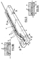
- Figure 2 is a sectional and elevational view of the lower part of a mechanism fixed on an adapter of the reactor vessel cover nuclear.
- Figure 3 is an enlarged sectional view of the lower part of the mechanism shown in the figure 2.
- FIG. 3A is an enlarged view of detail A of Figure 3.
- Figure 3B is a view along B of the figure 3A.
- Figures 4A and 4B are plan views of a support and displacement blade according to the invention and according to two variant embodiments.
- Figure 5 is a sectional view along 5-5 of Figure 4A or Figure 4B.
- Figure 6 is a sectional view along 6-6 of Figure 4A or Figure 4B.
- Figure 7 is a sectional view along 7-7 of Figure 4A or Figure 4B.
- Figure 8 is a plan view of part internal of the support blade shown in the figure 4A or in Figure 4B.
- Figure 9 is a perspective view of a mold open containing an insert, illustrating one of the phases of the manufacturing process by molding the blade support as shown in Figures 4A and 4B.
- Figures 9A and 9B are sectional views along A-A and B-B in Figure 9, respectively, showing the mold of Figure 9 closed by a cover.
- the mechanism comprises a tubular casing 2 of substantially cylindrical shape with the lower part has a thread 2a for fixing of the mechanism on the threaded upper part of a tank cover feedthrough adapter reactor, as shown in Figure 2.
- Mechanism 1 also has three coils electromagnetic actuators 3a, 3b and 3c allowing to move pieces of ferromagnetic material arranged in the inner bore of the housing 2.
- Ferromagnetic parts whose displacement is controlled by the windings 3a, 3b and 3c are shaped tubular and are mounted around a fixed part of the mechanism integral with the casing 2 in which is mounted sliding in the vertical direction a control rod 4 comprising a lower part 4a which comprises means for fixing an absorbent cluster constituting the control bar whose mechanism 1 ensures the displacement in the core of the nuclear reactor.
- the control rod 4 has a part 4b machined to present successive grooves, in the axial direction, delimiting between them teeth for the step-by-step movement of the control rod at which a control bar is attached.
- Moving the control bar, in the vertical direction, step by step, is provided by the assembly electromagnetic 3a constituting a lifting assembly of the control bar and two grabs 5a and 5b formed by a set of pawls which are controlled by the windings 3b and 3c to engage with the toothing 4b of the control rod 4 or to release the control rod.
- the pawls of the grapple 5a are fixed on a moving part which accompanies the control rod 4 during lifting it and which is returned to its initial position after an elementary displacement of the rod ordered.
- the grapple pawls 5b are pawls of support which maintain the control rod 4 and the cluster attached to this rod between two displacements one step of the control rod.
- the adapter 7 has, at its upper part, above the cover 6, a portion 8 diametrically widened having an external thread on which can be screwed the casing 2 of a movement mechanism 1 a command bar.
- a thermal cuff 9 comprising, at its lower part, a tulip 9a enabling re-engagement of the control rods in the corresponding adapters, when replacing the tank cover, after a nuclear reactor shutdown.
- the lower part of mechanism 1, which is shown in Figure 2 includes in particular the coil 3c for actuating the holding pawls and the assembly 5b of the retaining pawls.
- the axis vertical 10 In the bore of the casing 2 having for axis the axis vertical 10 is fixed, in a coaxial arrangement by relative to the casing, a tubular support 11 on which are pivotally mounted, via a horizontal axis pivot, the retaining pawls such as the pawl 12 shown in FIG. 3.
- Each set of ratchets has three ratchets arranged at 120 ° one of the other around axis 10.
- ferromagnetic parts are fixed or divers allowing control of each holding pawls, via a link 13 articulated at one of its ends on a ratchet and at its other end on a part 14 of tubular shape of the plunger of the retaining pawls.
- the part 14 of the retaining pawl is fixed by screwing on a second tubular part 15, in a coaxial arrangement.
- the second part 15 of the ratchet plunger of holding constitutes the pole piece of the plunger which is attracted by a fixed metal part 16, when feeds the magnetic winding 3c of the pawls maintenance.
- the diver is called back down by a spring 17 interposed between the fixed part 16 integral of the tubular support 11 and the pole piece 15 of the plunger retaining pawls.
- the part 14 is crossed by an opening in which a cup 19 is introduced and fixed by crimping metal sheet in which the head of the screw 18 which is screwed inside an opening tapped 20 crossing part of the part 15 coming facing the opening of the part 14 when we have carried out the assembly by screwing of parts 14 and 15.
- the screw 18 is made to rotate by deformation and crimping of two parts 19a and 19b of the cup 19 in two recesses of the head of the screw 18.
- the head of the screw 18 can come in protrusion inside the free space 21 formed between the outer surface of parts 14 and 15 of the plunger and the inner surface of the casing 2 of the mechanism 1. Because that the free space 21 has a small width in the radial direction, of the order of 3 mm, the screw head can come to rub against the surface inside of casing 2 of the mechanism, which can disturb or prevent the displacement of the pole pieces 14 and 15 actuating the retaining pawls 12.
- Such faulty operation is particularly undesirable when preventing a command bar to fall back into position of maximum insertion in the core of the nuclear reactor in the event of an emergency shutdown.
- This control can be carried out by optical examination, so as to control the position of the screw head 18 and check that this head is not protruding relative to the outer surface of the pieces of retaining pawl plungers 14 and 15.
- an optical examination means can only be done through the inside of the thermal cuff 9 of the adapter 7 on which the mechanism is fixed 1, after shutdown and cooling of the nuclear reactor and dismantling of the cover which is deposited on a support, in a room equipped with a handling arm allowing to introduce examination equipment inside the thermal cuffs of each of the bushing adapters of the cover, successively.
- the cover In this position allowing the control of adapters in particular, the cover is placed horizontally on the support, so that the adapters are arranged vertically.
- Tests have been carried out using camera elements attached to the end of a metal blade flat of a type already used to carry out the checking the internal surface of bushing adapters a tank cover using an inserted probe in the annular space between the thermal cuff and the adapter.
- Such a metal blade or saber has a thin between 1 and 2 mm and a width of the order of 10 to 15 mm.
- the length of the blade must be sufficient for the device to be sent optical examination in the area of the screw 18, from the lower part of the adapter thermal sleeve 9 constituted by the introductory tulip 9a.
- the optical examination device support saber To reach the annular space 21 from of the interior space of the thermal sleeve 9, the optical examination device support saber must be oriented towards a narrow passage 22 (Figure 3) formed between a peripheral part of the end bottom of part 14 of the ratchet plunger and part of the internal bore of the casing 2 of frustoconical shape placed between two parts with different diameters of this bore.
- the space 22 has a narrow width of around 1.6 mm.
- this passage 22 is located in an area device of the mechanism which is not level with the area with screw 18.
- the support blade of the optical examination device must therefore first be oriented in one direction inclined shown in Figure 3 to be introduced in passage 22 then must undergo a bending to penetrate in ring game 21 and finally a certain twist around axis 10 to reach the area of screw 18.
- a support blade has been produced and moving a new type, as shown in particular in Figures 4A and 4B.
- the blade 24 has a straight portion 24a of flat shape, the section of which is shown in the figure 6 and a curved portion 24b in the extension of the rectilinear part 24a which ends at the level of the head optical examination 24c carrying the optical elements 26 of the examination device fixed to the end of the blade 24.
- the 24c optical examination head also has two parts 27a and 27b thinner than the thickness of the blade and inclined with respect to the plane of the blade, of a same side of this plan.
- the blade 24 is connected to a section 28 section circular constituting the end of a connecting cable blade 24 and a set of signal processing optics provided by the elements 26.
- Optical signals are transmitted between the head optical examination comprising the optical elements 26 and the means of signal processing, by beams of optical fibers 29 arranged inside the blade 24 along its entire length.
- Each of the fiber bundles 29 can comprise a very large number of fibers, of the order of 10,000.
- the blade 24 is made completely monobloc in a thermoplastic material such as an elastomer.
- the fiber optic bundles 29 are completely embedded in the plastic material constituting the blade 24, so that the optical fibers are completely isolated from the outside environment and are not susceptible to come into contact with part of the mechanisms during the movement of the support blade between its operating position for examination of the screw 18 inside mechanisms and an outside withdrawal position of the mechanism. This avoids any deterioration fibers during the movement of the blade inside mechanisms.
- Slides 27a and 27b of the optical examination head 24c which constitute support and retaining springs of the blade inside the annular space 21 of the mechanism are also made in one piece with the body of the blade 24 of rectangular section.
- a blade of support having a thickness of the order of 1.4 mm, a width of 12 mm and a length from the end of the part 28 of the blade to the end of the head 24c optical examination, of the order of 500 mm.
- a polyurethane was preferably used for constitute the body of the blade 24 in which are embedded fiber optic bundles 29.
- Polyurethane has the advantage of having a high tensile strength, very high flexibility, low coefficient of friction on surfaces metallic, for example steel, less than 0.1, and high wear resistance when in contact rubbing with metal surfaces.
- the blades produced according to the invention having the dimensions mentioned above have resistance tensile strength of the order of 45 daN. We were able to realize and use blades according to the technique described having a resistance between 20 and 80 daN, which allows to avoid any risk of breaking the conditions of use for moving an examination device optics inside the annular space of mechanisms for moving control bars.
- plastics than polyurethane can be used to achieve the body of the blade and for example, silicones, polytetrafluoroethylene (Teflon), polyethylene or even polypropylene, to the extent that these plastics are acceptable as "usable products and materials nuclear power plant. "
- the optical devices 26 fixed at the end of the optical examination head 24c have elements optics for aiming in the axial direction to check that the screw head is not in projection in the annular space and optical elements radial sight to provide an image of the screw head and the crimp lock cup.
- the light signals recovered by the fibers of the bundles 29 in the area of the screw head which is lit up through a bundle of fibers are transmitted by optical fiber bundles arranged at inside and in the longitudinal direction of the body of the support and displacement blade 24 and at the inside of an optical cable extending the part end 28 of the blade. Signals get there to operating means making it possible to reconstruct an image of the screw head in axial sight and in sight radial.
- These means include in particular cameras CCD and a processing computer.
- the mechanical properties of the support blade and displacement as well as its geometric shape allow to facilitate the movement of this blade in the cramped and non-rectilinear space formed by the passage the blade at the bottom of the mechanisms and through the annular space between the plunger retaining pawls and the inner surface of the mechanism housing.
- the tensile strength of the blade polyurethane support which is of the order of 45 daN, in the case of the embodiment described, avoids risks of breakage of the blade inside a mechanism.
- Deflection and introduction of the blade into the access passage to the annular space of the mechanism are made by a device introduced inside the adapter thermal sleeve.
- the blade has in particular a core or insert consisting of fiber optic bundles 29 and means for holding these bundles of fibers in parallel arrangements in the longitudinal direction of the support blade.
- the nucleus or insert consisting of bundles of optical fibers (six bundles of parallel optical fibers have been shown in FIG. 8) and holding plates 30 bundles of optical fibers 29 grouped two by two, in parallel arrangements following the direction longitudinal of the blade.
- the plates 30 can be constituted by polyurethane wafers drilled so that present a network of openings 31 in which are engaged the fiber optic bundles 29 which are thus kept in parallel arrangements between them.
- At one end of the fiber bundles optics 29 are fixed optical means 26 allowing to pick up the optical signals which are then transmitted by the fibers of the bundles 29 to the processing means and image reconstruction.
- the fiber bundles 29 extend at the end of the blade opposite the optical examination head 24c comprising the optical means 26, inside a optical cable with circular section (see figure 7).
- the core or insert 32 of the blade made up of fiber bundles 29 and holding plates 30, inside the cavity of a mold 33.
- the insert 32 is shaped so as to have a curved part at the end of which are fixed the optical means 26 of the examination head 24c optic.
- the mold can be closed by a lid 34 coming to rest on the upper surface of the mold 33 in two parts support 33a and 33b of reduced surface.
- Lid 34 ensures the closing of the mold cavity in which insert 32 is inserted, in particular fiber bundles 29.
- the mold 33 comprises an insert 36 in which is machined a part of the mold cavity which is extended laterally by oblique cavities constituting the imprints molding 27'a and 27'b of springs 27a and 27b, as it is visible in Figure 9B.
- Channels 25 for recovering the polymerizable product in excess, during molding, are placed on the side and on the other side of the mold cavity.
- the implementation of the method has shown that the polyurethane is perfectly adherent on the fibers and on the spacers.
- the introduction of polyurethane in the openings 31 of the plates 30 as well as the coating of the fiber bundles 29 in the polyurethane allows to realize a very resistant bond between the plastic material of the blade and the elements which are fixed inside the blade.
- the realization in one piece of the blade and in particular, the realization in one piece of the blade and springs 27a, 27b avoid any risk an element of the blade comes off inside the mechanisms, during the optical examination.
- the elements of examination device entering the mechanisms are therefore totally captive. This captivity does not could be obtained only very difficult in the case of a metal blade.
- the plastic or elastomer blade molding in another way, for example by injecting the material hot plastic in a closed mold containing the insert. In all cases, the molding is carried out from so as to completely coat the fiber bundles optics and spacers in the blade in plastic or elastomer.
- the invention is not limited to the embodiment that has been described. This is how we can use materials other than polyurethane to achieve the blade body surrounding the fiber optic bundles.
- the spacing and holding plates conductors can be made of an identical material to the material constituting the body of the blade or a different material.
- the inserts arranged inside the mold forming the blade and which constitute, after molding, internal elements of the blade can have shapes and arrangements different from those which have been described.
- the invention applies to optical examinations of different objects of fixing screws of constituent parts of ratchet plungers of displacement mechanisms command bars.
- the blade of support and displacement according to the invention can be used to perform optical examinations or controls in many parts of a nuclear reactor or in other industrial installations with elements to be performed examination or control and accessible by passages cramped and not straight.
Landscapes
- Physics & Mathematics (AREA)
- General Physics & Mathematics (AREA)
- Optics & Photonics (AREA)
- Astronomy & Astrophysics (AREA)
- Monitoring And Testing Of Nuclear Reactors (AREA)
- Investigating Strength Of Materials By Application Of Mechanical Stress (AREA)
- Heating, Cooling, Or Curing Plastics Or The Like In General (AREA)
Claims (13)
- Lamelle zum Tragen und Verschieben, in einem engen und nicht geradlinigen Durchlaß (21), einer Untersuchungs- oder Kontröllvorrichtung (26) für ein durch den engen Durchlaß (21) zugängliches Element einer Industrieanlage, die an einem der Längsenden der Trägerlamelle (24) befestigt und für ihre Stromzuführ und das Auffangen von Signalen mit mehreren Leitern (29) verbunden ist, die entlang der Länge der Lamelle (24) angeordnet sind, dadurch gekennzeichnet, daß sie aus einem einstückigen Bauteil aus einem geformten Kunststoffmaterial besteht, das eine Zugfestigkeit zwischen 20 und 80 daN, und vorzugsweise in der Größenordnung von 45 daN, sowie einen Reibungskoeffizienten auf Stahl von weniger als 0,1 und eine hohe Abnutzungsfestigkeit im Fall eines Reibkontakts mit einer metallischen Oberfläche aufweist, wobei die mit der Untersuchungs- oder Kontrollvorrichtung (26) verbundenen Leiter (29) über die ganze Länge der Lamelle (24) vollständig vom Kunststoffmaterial der Lamelle (24) umhüllt sind.
- Träger- und Verschiebelamelle nach Anspruch 1, dadurch gekennzeichnet, daß die Leiter (29) aus Bündeln von Lichtleitfasern bestehen, und daß die Untersuchungsvorrichtung (26) eine optische Untersuchungsvorrichtung ist.
- Trägerlamelle nach einem der Ansprüche 1 und 2, dadurch gekennzeichnet, daß das Polymermaterial der Lamelle (24) Polyurethan ist.
- Trägerlamelle nach einem der Ansprüche 1 bis 3, dadurch gekennzeichnet, daß sie an einem ihrer Enden einen Kopf (24c) für eine optische Untersuchung oder Kontrolle aufweist, der Elemente (26) für die optische Untersuchung oder Kontrollelemente trägt und seitliche Verlängerungen (27a, 27b) aufweist, die in einem Stück mit der Trägerlamelle hergestellt werden und in bezug auf die Flächen der Lamelle (24) geneigt sind und Haltefedern für den Kopf (24c) für die optische Untersuchung oder Kontrolle im engen Durchlaß (21) bilden.
- Trägerlamelle nach einem der Ansprüche 1 bis 4, dadurch gekennzeichnet, daß sie nacheinander entlang ihrer Länge einen geradlinigen Bereich (24a) und einen gekrümmten Bereich (24b) aufweist, an dessen Ende die Vorrichtung zur Untersuchung oder Kontrolle (26) befestigt ist.
- Trägerlamelle nach Anspruch 5, dadurch gekennzeichnet, daß die Leiter (29) in der Verlängerung der Lamelle (24) ausgehend von dem Ende der Lamelle entgegengesetzt zu demjenigen, welches die Untersuchungs- oder Kontrollvorrichtung trägt, im Inneren eines Kabels mit kreisförmigem Querschnitt angeordnet sind.
- Verfahren zur Herstellung einer Träger- und Verschiebelamelle nach einem der Ansprüche 1 bis 6, dadurch gekennzeichnet, daßein Kern oder Einsatz hergestellt wird, der die Leiter (29) aufweist, die in im wesentlichen parallelen Anordnungen eingesetzt sind,der Kern oder Einsatz (32) in eine Form (33) mit einem Hohlraum gebracht wird, der die Form der herzustellenden Trägerlamelle hat, unddas Formen eines Kunststoffmaterials in der Form um den Kern oder Einsatz herum durchgeführt wird.
- Verfahren nach Anspruch 7, dadurch gekennzeichnet, daß die Form mit einem polymerisierbaren Material gefüllt und das polymerisierbare Material innerhalb der Form polymerisiert wird.
- Verfahren nach Anspruch 8, dadurch gekennzeichnet, daß die auf eine Temperatur von 30 bis 35°C gebrachte Form (33) mit einer polymerisierbaren Zubereitung mit einer Temperatur von 30 bis 35°C gefüllt wird, die ein Polyurethan bilden soll, und das polymerisierbare Material innerhalb der Form bei einer Temperatur zwischen 35 und 40°C polymerisiert wird.
- Verfahren nach einem der Ansprüche 7 bis 9, dadurch gekennzeichnet, daß der Kern oder Einsatz Abstandshalterplatten (30) aufweist, die von einem Netz von Öffnungen (31) durchquert werden, in die die Leiter (29) in parallelen Anordnungen eingeführt sind, wobei die Abstandshalterplatten (30) in Längsrichtung der Leiter (29) einen Abstand zueinander aufweisen.
- Verfahren nach Anspruch 10, dadurch gekennzeichnet, daß die Abstandshalterplatten (30) aus einem Kunststoffmaterial gleich dem Material des einstückigen geformten Bauteils der Trägerund Verschiebelamelle (24) geformt sind.
- Verwendung einer Träger- und Verschiebelamelle nach einem der Ansprüche 1 bis 6 zur Durchführung einer optischen Untersuchung eines Elements (18) innerhalb eines Gehäuses (2) eines Mechanismus (1) zur Verschiebung eines Steuerstabs eines Druckwasser-Kernreaktors.
- Verwendung nach Anspruch 12, dadurch gekennzeichnet, daß das Element (18) eine Schraube zum Zusammenbau von zwei Teilen (14, 15) eines Kolbens einer Halteklinke des Mechanismus (1) ist, die von einer elektromagnetischen Wicklung (3c) betätigt wird.
Applications Claiming Priority (2)
| Application Number | Priority Date | Filing Date | Title |
|---|---|---|---|
| FR9613273 | 1996-10-30 | ||
| FR9613273A FR2755229B1 (fr) | 1996-10-30 | 1996-10-30 | Lame de support et de deplacement d'un dispositif d'examen ou de controle, procede de fabrication de la lame et son utilisation |
Publications (2)
| Publication Number | Publication Date |
|---|---|
| EP0840097A1 EP0840097A1 (de) | 1998-05-06 |
| EP0840097B1 true EP0840097B1 (de) | 2002-09-11 |
Family
ID=9497191
Family Applications (1)
| Application Number | Title | Priority Date | Filing Date |
|---|---|---|---|
| EP19970402462 Expired - Lifetime EP0840097B1 (de) | 1996-10-30 | 1997-10-17 | Bewegliche Trägervorrichtung für eine Untersuchungs- oder Kontrollvorrichtung, sowie Verfahren zu deren Herstellung und Verwendung |
Country Status (3)
| Country | Link |
|---|---|
| EP (1) | EP0840097B1 (de) |
| ES (1) | ES2183104T3 (de) |
| FR (1) | FR2755229B1 (de) |
Family Cites Families (6)
| Publication number | Priority date | Publication date | Assignee | Title |
|---|---|---|---|---|
| JPS59143105A (ja) * | 1983-02-04 | 1984-08-16 | Furukawa Electric Co Ltd:The | 光フアイバアレイ及びその製造方法 |
| US5192278A (en) * | 1985-03-22 | 1993-03-09 | Massachusetts Institute Of Technology | Multi-fiber plug for a laser catheter |
| JPS6239813A (ja) * | 1985-08-15 | 1987-02-20 | Sumitomo Electric Ind Ltd | 内視鏡カテ−テル |
| JPH0219129A (ja) * | 1988-07-08 | 1990-01-23 | Toshiba Corp | 内視鏡装置 |
| DE3936007A1 (de) * | 1989-10-28 | 1991-05-02 | Rheydt Kabelwerk Ag | Optisches kabel |
| JPH0651141A (ja) * | 1992-07-31 | 1994-02-25 | Mitsubishi Rayon Co Ltd | プラスチック製マルチフィラメント型光ファイバの製法およびそれを用いた内視鏡用光ファイバ |
-
1996
- 1996-10-30 FR FR9613273A patent/FR2755229B1/fr not_active Expired - Fee Related
-
1997
- 1997-10-17 ES ES97402462T patent/ES2183104T3/es not_active Expired - Lifetime
- 1997-10-17 EP EP19970402462 patent/EP0840097B1/de not_active Expired - Lifetime
Also Published As
| Publication number | Publication date |
|---|---|
| EP0840097A1 (de) | 1998-05-06 |
| FR2755229B1 (fr) | 1999-01-15 |
| ES2183104T3 (es) | 2003-03-16 |
| FR2755229A1 (fr) | 1998-04-30 |
Similar Documents
| Publication | Publication Date | Title |
|---|---|---|
| EP0346170B1 (de) | Vorrichtung zum Messen von Parametern in der Spaltzone eines im Betrieb befindlichen Kernreaktors | |
| EP0753861B1 (de) | Vorrichtung zum selbsttätigen Entkoppeln eines Antriebstabs und einer Absorberanordnung eines Kernreaktors | |
| EP0245134B1 (de) | Verfahren und Vorrichtung zum Einbringen einer Hülse in ein Peripherierohr eines Dampferzeugers | |
| CA1306522C (fr) | Element a memoire de forme pour raccord de tresse sur connecteur | |
| FR2733005A1 (fr) | Cable de diagraphie | |
| EP0399863A1 (de) | Einrichtung zum Einbringen und Positionieren eines Gerätes in ein Rohr eines Dampferzeugers und Gebrauch dieser Einrichtung | |
| EP0840097B1 (de) | Bewegliche Trägervorrichtung für eine Untersuchungs- oder Kontrollvorrichtung, sowie Verfahren zu deren Herstellung und Verwendung | |
| BE897757A (fr) | Dispositif de prehension pour retirer simultanement une multiplicite de barres de combustible d'un assemblage combustible nucleaire | |
| CA2343596C (fr) | Dispositif de connexion electrique et dispositif de distribution de puissance le comportant | |
| EP0275773B1 (de) | Verkabelungseinrichtung zur Verbindung elektrischer Geräte bei Kernreaktoren | |
| EP0123607A1 (de) | Niederhaltungsvorrichtung für Kernreaktor | |
| FR2491220A1 (fr) | Cable optique comportant au moins un element compose d'au moins une fibre optique enrobee dans une gaine de matiere plastique, l'element ou l'ensemble d'elements etant maintenu a l'interieur d'un tube protecteur metallique | |
| WO2011033220A1 (fr) | Dispositif d'aide sous eau à l'extraction ou à l'insertion d'un élément de forme allongée disposé dans un conduit et procédé d'aide à l'extraction ou à l'insertion d'un tel élément | |
| EP2724047B1 (de) | Federvorrichtung | |
| FR2749435A1 (fr) | Dispositif de desaccouplement d'une tige de commande d'un element absorbant pour reacteur nucleaire | |
| EP0208596A1 (de) | Schwingungsdämpfer für Schleppkörper | |
| EP0285464B1 (de) | Erhitzungsvorrichtung, insbesondere zur Wärmebehandlung von gebogenen Rohren mit niedrigem Durchmesser | |
| EP0449736B1 (de) | Wärmeschutzschild | |
| EP0077245B1 (de) | Manipulator zum fernbedienbaren Eingreifen im Wasserbehälter eines Dampferzeugers | |
| FR2534700A1 (fr) | Dispositif de separation et de protection de fibres optiques a partir d'un cable optique | |
| FR2596859A1 (fr) | Dispositif de mesure a distance du diametre exterieur d'un element de forme cylindrique saillant par rapport a la surface d'une plaque | |
| FR2755239A1 (fr) | Procede et dispositif d'examen optique d'un element dispose a l'interieur d'un mecanisme de deplacement d'une barre de commande d'un reacteur nucleaire refroidi par de l'eau sous pression | |
| FR2575582A1 (fr) | Dispositif et procede d'accrochage pour tige de manoeuvre de grappe de commande dans un reacteur nucleaire | |
| EP0245167A1 (de) | Spaltzonenverschlussdeckel eines schnellen Neutronenkernreaktors | |
| EP3542372A1 (de) | Unterwasserbeleuchtungsvorrichtung zur visuellen inspektion von kernreaktoranlagen und entsprechendes verfahren |
Legal Events
| Date | Code | Title | Description |
|---|---|---|---|
| PUAI | Public reference made under article 153(3) epc to a published international application that has entered the european phase |
Free format text: ORIGINAL CODE: 0009012 |
|
| AK | Designated contracting states |
Kind code of ref document: A1 Designated state(s): BE CH ES LI SE |
|
| AX | Request for extension of the european patent |
Free format text: AL;LT;LV;RO;SI |
|
| 17P | Request for examination filed |
Effective date: 19980404 |
|
| AKX | Designation fees paid |
Free format text: BE CH ES LI SE |
|
| RBV | Designated contracting states (corrected) |
Designated state(s): BE CH ES LI SE |
|
| REG | Reference to a national code |
Ref country code: DE Ref legal event code: 8566 |
|
| 17Q | First examination report despatched |
Effective date: 20010521 |
|
| GRAG | Despatch of communication of intention to grant |
Free format text: ORIGINAL CODE: EPIDOS AGRA |
|
| GRAG | Despatch of communication of intention to grant |
Free format text: ORIGINAL CODE: EPIDOS AGRA |
|
| GRAH | Despatch of communication of intention to grant a patent |
Free format text: ORIGINAL CODE: EPIDOS IGRA |
|
| GRAH | Despatch of communication of intention to grant a patent |
Free format text: ORIGINAL CODE: EPIDOS IGRA |
|
| GRAA | (expected) grant |
Free format text: ORIGINAL CODE: 0009210 |
|
| AK | Designated contracting states |
Kind code of ref document: B1 Designated state(s): BE CH ES LI SE |
|
| REG | Reference to a national code |
Ref country code: CH Ref legal event code: EP |
|
| RAP2 | Party data changed (patent owner data changed or rights of a patent transferred) |
Owner name: FRAMATOME ANP |
|
| REG | Reference to a national code |
Ref country code: ES Ref legal event code: FG2A Ref document number: 2183104 Country of ref document: ES Kind code of ref document: T3 |
|
| PLBE | No opposition filed within time limit |
Free format text: ORIGINAL CODE: 0009261 |
|
| STAA | Information on the status of an ep patent application or granted ep patent |
Free format text: STATUS: NO OPPOSITION FILED WITHIN TIME LIMIT |
|
| 26N | No opposition filed |
Effective date: 20030612 |
|
| PGFP | Annual fee paid to national office [announced via postgrant information from national office to epo] |
Ref country code: SE Payment date: 20031021 Year of fee payment: 7 |
|
| PGFP | Annual fee paid to national office [announced via postgrant information from national office to epo] |
Ref country code: CH Payment date: 20031022 Year of fee payment: 7 |
|
| PGFP | Annual fee paid to national office [announced via postgrant information from national office to epo] |
Ref country code: ES Payment date: 20031107 Year of fee payment: 7 |
|
| PGFP | Annual fee paid to national office [announced via postgrant information from national office to epo] |
Ref country code: BE Payment date: 20031125 Year of fee payment: 7 |
|
| PG25 | Lapsed in a contracting state [announced via postgrant information from national office to epo] |
Ref country code: SE Free format text: LAPSE BECAUSE OF NON-PAYMENT OF DUE FEES Effective date: 20041018 Ref country code: ES Free format text: LAPSE BECAUSE OF NON-PAYMENT OF DUE FEES Effective date: 20041018 |
|
| PG25 | Lapsed in a contracting state [announced via postgrant information from national office to epo] |
Ref country code: LI Free format text: LAPSE BECAUSE OF NON-PAYMENT OF DUE FEES Effective date: 20041031 Ref country code: CH Free format text: LAPSE BECAUSE OF NON-PAYMENT OF DUE FEES Effective date: 20041031 Ref country code: BE Free format text: LAPSE BECAUSE OF NON-PAYMENT OF DUE FEES Effective date: 20041031 |
|
| BERE | Be: lapsed |
Owner name: *FRAMATOME Effective date: 20041031 |
|
| EUG | Se: european patent has lapsed | ||
| REG | Reference to a national code |
Ref country code: CH Ref legal event code: PL |
|
| REG | Reference to a national code |
Ref country code: ES Ref legal event code: FD2A Effective date: 20041018 |
|
| BERE | Be: lapsed |
Owner name: *FRAMATOME Effective date: 20041031 |