EP0839331B1 - Proximaler schnuppverbindungsstecker zum montieren eines faseroptischen elements in ein lichtquellensystem - Google Patents
Proximaler schnuppverbindungsstecker zum montieren eines faseroptischen elements in ein lichtquellensystem Download PDFInfo
- Publication number
- EP0839331B1 EP0839331B1 EP96924490A EP96924490A EP0839331B1 EP 0839331 B1 EP0839331 B1 EP 0839331B1 EP 96924490 A EP96924490 A EP 96924490A EP 96924490 A EP96924490 A EP 96924490A EP 0839331 B1 EP0839331 B1 EP 0839331B1
- Authority
- EP
- European Patent Office
- Prior art keywords
- ferrule
- aperture
- optic fiber
- housing
- fiber element
- Prior art date
- Legal status (The legal status is an assumption and is not a legal conclusion. Google has not performed a legal analysis and makes no representation as to the accuracy of the status listed.)
- Expired - Lifetime
Links
Images

Classifications
-
- G—PHYSICS
- G02—OPTICS
- G02B—OPTICAL ELEMENTS, SYSTEMS OR APPARATUS
- G02B6/00—Light guides; Structural details of arrangements comprising light guides and other optical elements, e.g. couplings
- G02B6/24—Coupling light guides
- G02B6/42—Coupling light guides with opto-electronic elements
-
- G—PHYSICS
- G02—OPTICS
- G02B—OPTICAL ELEMENTS, SYSTEMS OR APPARATUS
- G02B6/00—Light guides; Structural details of arrangements comprising light guides and other optical elements, e.g. couplings
- G02B6/24—Coupling light guides
- G02B6/36—Mechanical coupling means
- G02B6/38—Mechanical coupling means having fibre to fibre mating means
- G02B6/3807—Dismountable connectors, i.e. comprising plugs
- G02B6/389—Dismountable connectors, i.e. comprising plugs characterised by the method of fastening connecting plugs and sockets, e.g. screw- or nut-lock, snap-in, bayonet type
- G02B6/3893—Push-pull type, e.g. snap-in, push-on
-
- G—PHYSICS
- G02—OPTICS
- G02B—OPTICAL ELEMENTS, SYSTEMS OR APPARATUS
- G02B6/00—Light guides; Structural details of arrangements comprising light guides and other optical elements, e.g. couplings
- G02B6/24—Coupling light guides
- G02B6/36—Mechanical coupling means
- G02B6/38—Mechanical coupling means having fibre to fibre mating means
- G02B6/3807—Dismountable connectors, i.e. comprising plugs
- G02B6/3869—Mounting ferrules to connector body, i.e. plugs
-
- G—PHYSICS
- G02—OPTICS
- G02B—OPTICAL ELEMENTS, SYSTEMS OR APPARATUS
- G02B6/00—Light guides; Structural details of arrangements comprising light guides and other optical elements, e.g. couplings
- G02B6/24—Coupling light guides
- G02B6/42—Coupling light guides with opto-electronic elements
- G02B6/4292—Coupling light guides with opto-electronic elements the light guide being disconnectable from the opto-electronic element, e.g. mutually self aligning arrangements
-
- G—PHYSICS
- G02—OPTICS
- G02B—OPTICAL ELEMENTS, SYSTEMS OR APPARATUS
- G02B6/00—Light guides; Structural details of arrangements comprising light guides and other optical elements, e.g. couplings
- G02B6/24—Coupling light guides
- G02B6/42—Coupling light guides with opto-electronic elements
- G02B6/4296—Coupling light guides with opto-electronic elements coupling with sources of high radiant energy, e.g. high power lasers, high temperature light sources
Definitions
- the invention generally relates to optical systems for coupling light into a single optic fiber or fiber bundle and, in particular, to a connector for connecting a single optic fiber or fiber bundle into a housing of a light source system.
- a variety of light source systems have been developed for coupling light from a high intensity light source such as an arc lamp into an optical fiber bundle or single optical fiber.
- the light coupled into the bundle or single fiber may be used, for example, for medical illumination purposes such as for use with a surgical lummaire, headlamp, endoscope or borescope.
- a proximal end of the single fiber or fiber bundle is mounted within a proximal connector for insertion into a slot or aperture within a housing containing the light source.
- a distal end of the single fiber or fiber bundle is connected to an application device. i.e., a surgical luminaire, endoscope, etc.
- the proximal connector is configured to be removed from the light source system. This allows a person operating the application device, such as a surgeon using a surgical headlamp, to have free mobility, which may be otherwise hindered while the fiber or fiber bundle is connected into the light source system.
- the provision of the removable proximal connector also allows a singie light source system to be used to provide light for a variety of different application devices, each having a corresponding proximal connector.
- proximai connectors particularly those designed for use with a single optic fiber.
- Single fibers require high intensity light to be directed onto an entrance aperture of the single fiber held by the proximal connector.
- Conventional proximal connectors for single fibers generally support silica fibers for which heat is not a problem. If the materials or the optical fiber are susceptible to thermal damage, a method of removing the heat is necessary to assure continued operation. For silica fibers having a polymer cladding, excess heat of a conventional connector will destroy the cladding. To remedy this problem, some previous light source systems have been configured to position the proximal entrance aperture of the single fiber some distance from the proximal connector itself.
- the high intensity light is then focused at the entrance aperture of the singie fiber which is offset from the proximal connector itself.
- the proximal connector is not significantly heated.
- the entrance aperture of the single fiber extends from the proximal connector, the fiber is unprotected and easily broken or otherwise damaged after removal from the light source system.
- At least one proximal connector includes a slidable housing designed to protect the fiber.
- the housing retracts while the connector is mounted to the light source system to allow the single fiber to receive light.
- the slidable housing slides outwardly, as the connector is removed from the light source system to enclose and protect the optic fiber.
- proximal connectors having an optic fiber extending beyond the connector itself.
- single fibers require precise positioning of the entrance aperture of the fiber with respect to the optical components of the light source system which is complicated by having the fiber extend beyond the connector.
- polishing such fibers protruding beyond the proximal connectors is difficult and not readily manufacturable.
- a method of coupling light from a high intensity light source to a optic fiber element and a proximal connector for connecting an optic fiber element such as a single optic fiber or fiber bundle into a housing of a light source system are provided as defined in claims 1, 6.
- the proximal connector includes a cone-shaped ferrule mounted around a proximal end of the single fiber designed for both alignment and heat sinking.
- the cone-shaped ferrule is sized and configured for mounting within a cone-shaped slot or aperture within a receiving block of the housing. While inserted, an exterior sidewall of the cone-shaped ferrule rests snugly against an interior sidewall of the receiving block.
- High intensity light is directed into an entrance aperture of the proximal end of the single fiber.
- the entrance aperture is aligned with a truncated end of the cone-shaped ferrule.
- the cone-shaped ferrule and the receiving block are both formed of stainless steel or other metals or alloys having a high index of heat conduction. Accordingly, any heat generated within the cone-shaped ferrule from the high intensity light is conducted into the receiving block of the housing thereby keeping the cone-shaped ferrule, and the single fiber enclosed therein, relatively cool.
- the fiber optic does not extend from the truncated end of the cone-shaped ferrule, but lies flush therewith. Hence, upon removal from the housing, the optic fiber element is protected by the cone-shaped ferrule from possible damage. In this manner, heating problems and breakage problems are both substantially eliminated, without requiring a complicated and expensive mounting apparatus such as the type described above having a slidable external housing. Furthermore, the entrance aperture of the fiber optic can be polished because it is secured within the ferrule.
- the receiving block includes a spring-loaded ball plunger to ensure that the ferrule remains snugly mounted within the aperture of the receiving block.
- the ferrule is mounted in a case that includes an indented ring.
- the ball plunger and the indented ring are relatively positioned such that the ball plunger rests within the indented ring only while the ferrule is fully inserted within the aperture.
- the ball plunger prevents the ferrule from a sliding out from the aperture.
- the ball plunger holds the ferrule in place until sufficient manual force is applied to disengage the ball plunger. By holding the ferrule in place, lateral alignment, along the direction of insertion of the ferrule, of the entrance aperture of the single fiber is ensured.
- the cone-shaped ferrule and the matching aperture of the receiving block are both axially symmetric such that longitudinal alignment is also ensured.
- rotation of the ferrule within the aperture does not cause any displacement of the entrance aperture of the fiber but merely rotates the fiber, which itself is axially symmetric.
- positioning problems of the type discussed are also avoided.
- Figure 1 illustrates an illumination system 10 having, for example, a medical device 12 connected through a single fiber optic 14 to a light source system 16.
- Medical device 12 may be a surgical headlamp, surgical luminaire, endoscope, borescope, etc.
- Light source system 16 includes a high intensity light source 18, such as a metal halide or xenon arc lamp, and an optical system 20 for collecting and condensing light from source 18.
- Optical system 20 may include one or more optical elements such as mirrors, configured, for example, in accordance with the source system described in U.S. Patent 4,757,431.
- Fiber optic 14 includes a proximal connector 22 configured for "snap" insertion into an aperture formed in a receiving block of a housing of light source system 16. Proximal connector 22 and the receiving block in which it is inserted will now be described with reference to the remaining figures.
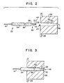
- Figure 2 provides a sideview of proximal connector 22 positioned prior to insertion into an aperture 24 of a receiving block 26 of a housing 28 of light source system 16.
- Proximal connector 22 includes a three-dimensional symmetrical profile matching the interior profile of aperture 24. More specifically, proximal connector 22 includes a stainless steel ferrule 30 having a cylindrical base portion 31 and a tapering cone-shaped tip 32 with a truncated end 33. Base portion 31 is mounted within a case 34 which is substantially right-cylindrical but includes an indented ring 36 offset a distance from a tapered, truncated portion 38.
- Optic fiber 14 is held within an internal bore within case 34 and ferrule 30.
- An entrance aperture 40 of optic fiber 14 lies flush with the front truncated end 33 of ferrule 30.
- aperture 24 includes cylindrical and conical portions having substantially the same size and shape as corresponding portions of the proximal connector.
- the aperture does not define an outwardly extending ring shaped to match indented ring 36.
- a ball plunger spring-biasing mechanism 42 is mounted along an inner sidewall 44 of housing block 26. Ball plunger 42 is positioned such that it engages with indented ring 36 only while the proximal connector is fully inserted within aperture 24. This is illustrated in Figure 3 . Ball plunger 42 thus allows the proximal connector to be snapped into place during insertion.
- the ball plunger prevents the proximal connector from accidentally sliding out of the aperture.
- the proximal connector can only be manually removed by pulling on the proximal connector with sufficient force to displace the ball plunger out of the indented ring allowing free removal of the connector.
- the ball plunger may be mounted to the case of the proximal connector with the ring formed within the housing.
- the case may be formed with a resilient outwardly extending ring and the aperture formed with a matching ring. Upon insertion of the proximal connector, the resilient ring of the case bends inwardly slightly until reaching the matching ring of the housing then snaps outwardly into the matching ring of the housing.
- the profile of the proximal connector is matched to the internal profile of the aperture of the receiving block, in part, to facilitate heat transfer from the connector into the receiving block.
- high intensity light is focused or condensed or otherwise directed to a point or spot 46 which corresponds to the entrance aperture of the optic fiber while the connector is inserted in the receiving block.
- the intensity of light in the vicinity of 46 causes ferrule 30 to heat.
- heat generated within the ferrule is quickly conducted away from the tip of the ferrule and ultimately into the receiving block.
- both the ferrule and the receiving block are formed of materials having a high index of heat conduction.
- a suitable material is stainless steel.
- the ferrule By conducting heat away from the tip of the ferrule, the ferrule remains relatively cool such that, on removal of the proximal connector, the ferrule does not need to be shielded and the persons touching the tip of the ferrule are not at risk from being burned.
- the dimensions of the proximal connector and of the aperture are fabricated to fairly close tolerances to ensure that the ferrule of the proximal connector contacts the inner walls of receiving block over the entire external surface area of the ferrule. Any gaps therebetween may hinder the conduction of heat from the ferrule.
- ferrule 30 may be formed of stainless steel.
- case 34 is formed of plastic.
- case 34 may also be formed of stainless steel.
- wide variety of choices of materials can be employed consistent with the principles of the invention.
- the particular cylindrical and conical shapes thus far described have been found to be effective, other shapes may also be effective.
- the shape of the ferrule should closely match the shape of the corresponding aperture, at least within the region of expected heat conduction. In other words, portions of the proximal connector and aperture which are remote from the end of the fiber need not match as closely since less heat conduction is required at positions remote from the end of the optic fiber.
- proximal connector and of the aperture are substantially axially symmetric.
- the proximal connector can be freely rotated within the aperture without displacing the entrance aperture of the optic fiber.
- precise axial positioning is maintained.
- Lateral positioning of the tip of the fiber along the direction of insertion is maintained by the ball plunger which rests within indented ring 36. Precise positioning of the entrance aperture of the fiber is thereby maintained.
- the entrance aperture of the fiber lies flush with the truncated end of the ferrule, the entrance aperture can be polished to provide improved optical characteristics.
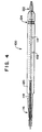
- Figure 4 provides a cross sectional illustration of a specific proximal connector configured as generally described with reference to Figures 1-3 .
- Figure 4 illustrates the internal structure of the proximal connector which holds the fiber optic.
- proximal connector 100 of Figure 4 includes a bore 102 through which fiber optic 114 passes. A distal portion of the optic fiber is secured by a clasp member 116 which also mounts to a cone-shaped distal end 118 of case 120.
- proximal connector 100 of Figure 4 includes a ferrule having a conic end 122.
- Case 120 also includes an indented longitudinally extending ring 124.
- proximal connector for use with an optical illumination system employing a single optic fiber.
- the invention enables the use of temperature sensitive materials in the construction of single optical fibers.
- Principles of the invention can be applied to other systems and to other applications as well.
- principles of the invention may be applicable to optical illumination systems incorporating other optical fiber elements such as fiber bundles or the like.
Landscapes
- Physics & Mathematics (AREA)
- General Physics & Mathematics (AREA)
- Optics & Photonics (AREA)
- Optical Couplings Of Light Guides (AREA)
- Endoscopes (AREA)
- Mechanical Coupling Of Light Guides (AREA)
Claims (9)
- Verfahren zum Koppeln von Licht von einer in einem Gehäuse (26, 28) angeordneten Lichtquelle hoher Intensität (18) mit einem Lichtwellenleiterelement (14) unter Verwendung eines Lichtkopplungssystems, bei dem (Verfahren) ein optisches System (20) zum Sammeln und Konzentrieren von Licht auf das Lichtwellenleiterelement (14) verwendet wird, wobei das Lichtwellenleiterelement abnehmbar in eine in dem Gehäuse ausgebildete Öffnung (24) eingeschoben ist,
mit den SchrittenMontieren eines Endes des Lichtwellenleiterelements in einer kegelförmigen Metallkappe (30), die aus einem Material mit einer hohen Wärmeleitzahl besteht, wobei das Lichtwellenleiterelement in der Metallkappe so gesichert wird, dass die Metallkappe einen Weg mit einem niedrigen Wärmewiderstand von dem Lichtwellenleiterelement zu der Seitenwand (44) der Öffnung bereitstellt, wenn die Metallkappe in die Öffnung geschoben wird, wobei die Eingangsöffnung des Lichtwellenleiterelements bündig mit dem Ende der Metallkappe abschließt;Konfigurieren der Öffnung des Gehäuses mit einer Kegelform, die zum nichtrutschenden Aufnehmen der kegelförmigen Metallkappe dimensioniert ist, und Bringen des Gehäuses und der Metallkappe in wärmeleitenden Kontakt, wobei die Seitenwand (44) der Öffnung des Gehäuses aus einem Material mit einer hohen Wärmeleitzahl besteht; undVersehen des Gehäuses und der Metallkappe mit zusammenwirkenden Einrastmitteln, sodass die Metallkappe geradlinig einrastbar und abziehbar so in die Öffnung geschoben werden kann, dass die genaue Ausrichtung zwischen dem Lichtwellenleiterelement und dem Lichtkopplungssystem aufrechterhalten wird und der Wärmetransport vom Lichtwellenleiterelement weg erleichtert wird. - Verfahren nach Anspruch 1, dadurch gekennzeichnet, dass das Material nichtrostender Stahl ist.
- Verfahren nach Anspruch 1, dadurch gekennzeichnet, dass die Metallkappe (30) in einem Gehäuse montiert wird, dass das Gehäuse (28) einen peripher verlaufenden Kerbring (36) hat und dass die Öffnung (24) eine unter Federspannung stehende Rastkugel (42) aufweist, die so angeordnet ist, dass sie nur dann mit dem Kerbring (36) in Eingriff kommt, wenn die Metallkappe (30) vollständig in die Öffnung (24) eingeschoben ist.
- Verfahren nach einem der Ansprüche 1 bis 3, dadurch gekennzeichnet, dass das Lichtwellenleiterelement (14) ein einzelner Lichtwellenleiter ist.
- Verfahren nach einem der Ansprüche 1 bis 4, dadurch gekennzeichnet, dass die Einrastmittel ein Einrastteil in der Öffnung aufweisen, um ein entsprechendes Aufnahmeteil, das an das Ende des Lichtwellenleiterelements (14) angrenzend montiert ist, einzurasten, wenn die Metallkappe (30) geradlinig einrastbar und abziehbar in die Öffnung eingeschoben wird.
- Lichtwellenleitervorrichtung mit
einer Lichtquelle hoher Intensität (18), die in einem Gehäuse (26, 28) mit einer kegelförmigen dimensionierten Öffnung mit einer Seitenwand aus einem Material mit einer hohen Wärmeleitzahl angeordnet ist;
einem Lichtwellenleiterelement (14);
einem in dem Gehäuse montierten optischen System (20), wobei das optische System und die Öffnung zum Einkoppeln von Licht von der Lichtquelle in das Lichtwellenleiterelement positioniert sind; und
einer an einem Ende des Lichtwellenleiterelements befestigten kegelförmigen Metallkappe (30), die aus einem Material mit einer hohen Wärmeleitzahl besteht und so konfiguriert ist, dass sie in der Öffnung nichtrutschend aufgenommen wird, um das Gehäuse und die Metallkappe in wärmeleitenden Kontakt zu bringen, wobei das Lichtwellenleiterelement in der Metallkappe so gesichert ist, dass die Metallkappe einen Weg mit einem niedrigen Wärmewiderstand von dem Lichtwellenleiterelement zu der Seitenwand der Öffnung bereitstellt, wenn die Metallkappe in die Öffnung eingeschoben ist, wobei die kegelförmige Metallkappe ein kegelstumpfartiges Ende (33) hat und die Eingangsöffnung des Lichtwellenleiterelements bündig mit dem Ende der Metallkappe abschließt,
dadurch gekennzeichnet, dass die Metallkappe ein Teil eines an dem Lichtwellenleiterelement angebrachten Anschlussglieds ist, das außerdem ein Mantelglied (34) aufweist, das einen Teil des Lichtwellenleiterelements umgibt und an der Metallkappe angebracht ist, wobei das Mantelglied einen peripher verlaufenden Kerbring (36) hat, um ein entsprechendes einrastbares Glied (42), das an der Seitenwand der Öffnung des Gehäuses angeordnet ist, einzurasten, wenn das Mantelglied geradlinig einrastbar und abziehbar in die Öffnung des Gehäuses geschoben wird. - Vorrichtung nach Anspruch 6, dadurch gekennzeichnet, dass das Material nichtrostender Stahl ist und das Lichtwellenleiterelement (14) ein einzelner Lichtwellenleiter ist.
- Vorrichtung nach Anspruch 6 oder 7, dadurch gekennzeichnet, dass das Lichtwellenleiterelement (14) ein einzelner Lichtwellenleiter ist.
- Vorrichtung nach einem der Ansprüche 6 bis 8, dadurch gekennzeichnet, dass die Lichtquelle (18) eine Bogenlampe ist.
Applications Claiming Priority (3)
| Application Number | Priority Date | Filing Date | Title |
|---|---|---|---|
| US502068 | 1995-07-14 | ||
| US08/502,068 US5640478A (en) | 1995-07-14 | 1995-07-14 | Snap-in proximal connector for mounting an optic fiber element into a light source system |
| PCT/US1996/011671 WO1997004341A1 (en) | 1995-07-14 | 1996-07-12 | Snap-in proximal connector for mounting an optic fiber element into a light source system |
Publications (2)
| Publication Number | Publication Date |
|---|---|
| EP0839331A1 EP0839331A1 (de) | 1998-05-06 |
| EP0839331B1 true EP0839331B1 (de) | 2003-05-14 |
Family
ID=23996194
Family Applications (1)
| Application Number | Title | Priority Date | Filing Date |
|---|---|---|---|
| EP96924490A Expired - Lifetime EP0839331B1 (de) | 1995-07-14 | 1996-07-12 | Proximaler schnuppverbindungsstecker zum montieren eines faseroptischen elements in ein lichtquellensystem |
Country Status (12)
| Country | Link |
|---|---|
| US (1) | US5640478A (de) |
| EP (1) | EP0839331B1 (de) |
| JP (1) | JP3178845B2 (de) |
| KR (1) | KR100287509B1 (de) |
| CN (1) | CN1098468C (de) |
| AT (1) | ATE240539T1 (de) |
| AU (1) | AU6492596A (de) |
| CA (1) | CA2226005A1 (de) |
| DE (2) | DE839331T1 (de) |
| IL (1) | IL122908A (de) |
| MX (1) | MX9800459A (de) |
| WO (1) | WO1997004341A1 (de) |
Families Citing this family (18)
| Publication number | Priority date | Publication date | Assignee | Title |
|---|---|---|---|---|
| US5764837A (en) * | 1995-07-14 | 1998-06-09 | Cogent Light Technologies, Inc. | Snap-in proximal connector for mounting an optic fiber element into a light source system |
| US6065882A (en) * | 1995-07-14 | 2000-05-23 | Cogent Light Technologies, Inc. | Snap-in proximal connector for mounting an optic fiber element into a light source system |
| US5872879A (en) * | 1996-11-25 | 1999-02-16 | Boston Scientific Corporation | Rotatable connecting optical fibers |
| DE19756143A1 (de) * | 1997-12-17 | 1999-06-24 | Hella Kg Hueck & Co | Vorrichtung und Verfahren zum Verbinden eines Lichtleiters mit einem Lichtkoppelelement |
| US6372334B1 (en) | 1998-03-30 | 2002-04-16 | Henkel Corporation | Reinforcement laminate |
| US6409391B1 (en) * | 1999-03-26 | 2002-06-25 | Cogent Light Technologies, Inc. | Fiber optic illumination adaptor assembly for multiple light guide connectors |
| US6456772B1 (en) * | 1999-09-21 | 2002-09-24 | Avaya Technology Corp. | System for removable attachment of two objects |
| US6626582B2 (en) * | 2000-02-17 | 2003-09-30 | Cogent Light Technologies, Inc. | Snap-on connector system for coupling light from an illuminator to a fiber optic |
| FR2805915B1 (fr) * | 2000-03-06 | 2002-08-23 | Texas De France | Transmetteur audio-video a sources multiples avec emetteur pour le retour de telecommande |
| US20070049098A1 (en) * | 2005-08-25 | 2007-03-01 | Feinbloom Richard E | Optical connector |
| US20070189031A1 (en) * | 2006-02-14 | 2007-08-16 | Delmar Stephen A | Method for making an abraded optical fiber illumination means |
| WO2017173419A1 (en) * | 2016-04-01 | 2017-10-05 | Ipg Photonics Corporation | Optic fiber cable connector |
| US9791636B1 (en) | 2016-06-24 | 2017-10-17 | Excelitas Technologies Corp. | Fiber optic ferrule coupling system |
| US10139567B1 (en) * | 2017-10-10 | 2018-11-27 | The United States Of America As Represented By The Secretary Of The Navy | Dematable expanded beam fiber optic connector |
| US10695578B1 (en) * | 2019-08-09 | 2020-06-30 | Hua Shang | Vascular optical fiber guidewire with plug |
| WO2021087122A1 (en) * | 2019-10-29 | 2021-05-06 | Ipg Photonics Corporation | Optical fiber cable connector |
| US11700704B2 (en) * | 2021-04-30 | 2023-07-11 | Quanta Computer Inc. | Adjustable air blocks for cable routing |
| DE102024117717B4 (de) * | 2024-06-24 | 2025-12-31 | Schott Ag | Montagevorrichtung für einen Lichtleiter |
Family Cites Families (9)
| Publication number | Priority date | Publication date | Assignee | Title |
|---|---|---|---|---|
| GB1456395A (en) * | 1973-11-16 | 1976-11-24 | Bicc Ltd | Optical fibre connector |
| US4273413A (en) * | 1979-02-26 | 1981-06-16 | Amp Incorporated | Photoelectric element/optical cable connector |
| JPS60201308A (ja) * | 1984-03-26 | 1985-10-11 | Sumitomo Electric Ind Ltd | 光フアイバ−端末固定装置 |
| US4737008A (en) * | 1984-10-01 | 1988-04-12 | Mitsumi Electric Co., Ltd. | Optical transmitting and/or receiving module |
| US4772081A (en) * | 1986-09-15 | 1988-09-20 | Tsi Incorporated | Fiber optic connector assembly |
| US4824202A (en) * | 1987-08-12 | 1989-04-25 | Alcon Laboratories, Inc. | Fiber optic connector |
| US4883333A (en) * | 1987-10-13 | 1989-11-28 | Yanez Serge J | Integrated, solid, optical device |
| US5142600A (en) * | 1991-02-25 | 1992-08-25 | General Electric Company | Optical fiber quick connect/disconnect for a power laser |
| SE9102851L (sv) * | 1991-06-17 | 1992-12-18 | Stratos Connectors Ab | Anordning foer optisk anslutning av ett optiskt element till en lins |
-
1995
- 1995-07-14 US US08/502,068 patent/US5640478A/en not_active Expired - Fee Related
-
1996
- 1996-07-12 IL IL12290896A patent/IL122908A/en not_active IP Right Cessation
- 1996-07-12 AT AT96924490T patent/ATE240539T1/de not_active IP Right Cessation
- 1996-07-12 CN CN96195435A patent/CN1098468C/zh not_active Expired - Fee Related
- 1996-07-12 AU AU64925/96A patent/AU6492596A/en not_active Abandoned
- 1996-07-12 WO PCT/US1996/011671 patent/WO1997004341A1/en not_active Ceased
- 1996-07-12 DE DE0839331T patent/DE839331T1/de active Pending
- 1996-07-12 EP EP96924490A patent/EP0839331B1/de not_active Expired - Lifetime
- 1996-07-12 CA CA002226005A patent/CA2226005A1/en not_active Abandoned
- 1996-07-12 KR KR1019980700255A patent/KR100287509B1/ko not_active Expired - Fee Related
- 1996-07-12 JP JP50677197A patent/JP3178845B2/ja not_active Expired - Fee Related
- 1996-07-12 DE DE69628169T patent/DE69628169T2/de not_active Expired - Fee Related
-
1998
- 1998-01-14 MX MX9800459A patent/MX9800459A/es not_active IP Right Cessation
Also Published As
| Publication number | Publication date |
|---|---|
| US5640478A (en) | 1997-06-17 |
| CN1190468A (zh) | 1998-08-12 |
| EP0839331A1 (de) | 1998-05-06 |
| KR100287509B1 (ko) | 2001-04-16 |
| IL122908A (en) | 2001-05-20 |
| ATE240539T1 (de) | 2003-05-15 |
| IL122908A0 (en) | 1998-08-16 |
| WO1997004341A1 (en) | 1997-02-06 |
| JPH11506844A (ja) | 1999-06-15 |
| DE839331T1 (de) | 1998-10-22 |
| DE69628169D1 (de) | 2003-06-18 |
| KR19990028953A (ko) | 1999-04-15 |
| MX9800459A (es) | 1998-11-30 |
| CN1098468C (zh) | 2003-01-08 |
| AU6492596A (en) | 1997-02-18 |
| CA2226005A1 (en) | 1997-02-06 |
| DE69628169T2 (de) | 2004-04-01 |
| JP3178845B2 (ja) | 2001-06-25 |
Similar Documents
| Publication | Publication Date | Title |
|---|---|---|
| EP0839331B1 (de) | Proximaler schnuppverbindungsstecker zum montieren eines faseroptischen elements in ein lichtquellensystem | |
| US6065882A (en) | Snap-in proximal connector for mounting an optic fiber element into a light source system | |
| TW494253B (en) | Snap-on connector system for coupling light from an illuminator to a fiber optic | |
| KR20010113862A (ko) | 다중 광 가이드 커넥터용 광섬유 조명기 어댑터 조립체 | |
| EP0919006B1 (de) | Vorrichtung und verfahren zur kupplung von licht hoher intensität in optische fasern niedriger temperatur | |
| US5764837A (en) | Snap-in proximal connector for mounting an optic fiber element into a light source system | |
| US5446818A (en) | Fiber optic connector having a shielding apparatus for protecting the exposed end of a fiber optic | |
| HK1023410B (en) | Snap-in proximal connector for mounting an optic fiber element into a light source system | |
| MXPA99008960A (es) | Conector contiguo a presion para el montaje de un elemento de fibra optica dentro de un sistema de fuente de luz | |
| HK1021841B (en) | Apparatus and method for coupling high intensity light into low temperature optical fiber | |
| MXPA00012007A (en) | Snap-in proximal connector for mounting an optic fiber element into a light source system |
Legal Events
| Date | Code | Title | Description |
|---|---|---|---|
| PUAI | Public reference made under article 153(3) epc to a published international application that has entered the european phase |
Free format text: ORIGINAL CODE: 0009012 |
|
| 17P | Request for examination filed |
Effective date: 19980119 |
|
| AK | Designated contracting states |
Kind code of ref document: A1 Designated state(s): AT BE CH DE DK ES FI FR GB GR IE IT LI LU MC NL PT SE |
|
| AX | Request for extension of the european patent |
Free format text: AL PAYMENT 980119;LT PAYMENT 980119;LV PAYMENT 980119;SI PAYMENT 980119 |
|
| EL | Fr: translation of claims filed | ||
| 17Q | First examination report despatched |
Effective date: 19980713 |
|
| DET | De: translation of patent claims | ||
| GRAH | Despatch of communication of intention to grant a patent |
Free format text: ORIGINAL CODE: EPIDOS IGRA |
|
| GRAH | Despatch of communication of intention to grant a patent |
Free format text: ORIGINAL CODE: EPIDOS IGRA |
|
| GRAA | (expected) grant |
Free format text: ORIGINAL CODE: 0009210 |
|
| AK | Designated contracting states |
Designated state(s): AT BE CH DE DK ES FI FR GB GR IE IT LI LU MC NL PT SE |
|
| AX | Request for extension of the european patent |
Extension state: AL LT LV SI |
|
| PG25 | Lapsed in a contracting state [announced via postgrant information from national office to epo] |
Ref country code: NL Free format text: LAPSE BECAUSE OF FAILURE TO SUBMIT A TRANSLATION OF THE DESCRIPTION OR TO PAY THE FEE WITHIN THE PRESCRIBED TIME-LIMIT Effective date: 20030514 Ref country code: LI Free format text: LAPSE BECAUSE OF FAILURE TO SUBMIT A TRANSLATION OF THE DESCRIPTION OR TO PAY THE FEE WITHIN THE PRESCRIBED TIME-LIMIT Effective date: 20030514 Ref country code: IT Free format text: LAPSE BECAUSE OF FAILURE TO SUBMIT A TRANSLATION OF THE DESCRIPTION OR TO PAY THE FEE WITHIN THE PRESCRIBED TIME-LIMIT;WARNING: LAPSES OF ITALIAN PATENTS WITH EFFECTIVE DATE BEFORE 2007 MAY HAVE OCCURRED AT ANY TIME BEFORE 2007. THE CORRECT EFFECTIVE DATE MAY BE DIFFERENT FROM THE ONE RECORDED. Effective date: 20030514 Ref country code: FR Free format text: LAPSE BECAUSE OF NON-PAYMENT OF DUE FEES Effective date: 20030514 Ref country code: FI Free format text: LAPSE BECAUSE OF FAILURE TO SUBMIT A TRANSLATION OF THE DESCRIPTION OR TO PAY THE FEE WITHIN THE PRESCRIBED TIME-LIMIT Effective date: 20030514 Ref country code: CH Free format text: LAPSE BECAUSE OF FAILURE TO SUBMIT A TRANSLATION OF THE DESCRIPTION OR TO PAY THE FEE WITHIN THE PRESCRIBED TIME-LIMIT Effective date: 20030514 Ref country code: BE Free format text: LAPSE BECAUSE OF FAILURE TO SUBMIT A TRANSLATION OF THE DESCRIPTION OR TO PAY THE FEE WITHIN THE PRESCRIBED TIME-LIMIT Effective date: 20030514 Ref country code: AT Free format text: LAPSE BECAUSE OF FAILURE TO SUBMIT A TRANSLATION OF THE DESCRIPTION OR TO PAY THE FEE WITHIN THE PRESCRIBED TIME-LIMIT Effective date: 20030514 |
|
| REG | Reference to a national code |
Ref country code: GB Ref legal event code: FG4D |
|
| REG | Reference to a national code |
Ref country code: CH Ref legal event code: EP |
|
| REG | Reference to a national code |
Ref country code: IE Ref legal event code: FG4D |
|
| REF | Corresponds to: |
Ref document number: 69628169 Country of ref document: DE Date of ref document: 20030618 Kind code of ref document: P |
|
| PG25 | Lapsed in a contracting state [announced via postgrant information from national office to epo] |
Ref country code: LU Free format text: LAPSE BECAUSE OF NON-PAYMENT OF DUE FEES Effective date: 20030712 |
|
| PG25 | Lapsed in a contracting state [announced via postgrant information from national office to epo] |
Ref country code: IE Free format text: LAPSE BECAUSE OF NON-PAYMENT OF DUE FEES Effective date: 20030714 |
|
| PG25 | Lapsed in a contracting state [announced via postgrant information from national office to epo] |
Ref country code: MC Free format text: LAPSE BECAUSE OF NON-PAYMENT OF DUE FEES Effective date: 20030731 |
|
| PG25 | Lapsed in a contracting state [announced via postgrant information from national office to epo] |
Ref country code: SE Free format text: LAPSE BECAUSE OF FAILURE TO SUBMIT A TRANSLATION OF THE DESCRIPTION OR TO PAY THE FEE WITHIN THE PRESCRIBED TIME-LIMIT Effective date: 20030814 Ref country code: PT Free format text: LAPSE BECAUSE OF FAILURE TO SUBMIT A TRANSLATION OF THE DESCRIPTION OR TO PAY THE FEE WITHIN THE PRESCRIBED TIME-LIMIT Effective date: 20030814 Ref country code: GR Free format text: LAPSE BECAUSE OF FAILURE TO SUBMIT A TRANSLATION OF THE DESCRIPTION OR TO PAY THE FEE WITHIN THE PRESCRIBED TIME-LIMIT Effective date: 20030814 Ref country code: DK Free format text: LAPSE BECAUSE OF FAILURE TO SUBMIT A TRANSLATION OF THE DESCRIPTION OR TO PAY THE FEE WITHIN THE PRESCRIBED TIME-LIMIT Effective date: 20030814 |
|
| PG25 | Lapsed in a contracting state [announced via postgrant information from national office to epo] |
Ref country code: ES Free format text: LAPSE BECAUSE OF FAILURE TO SUBMIT A TRANSLATION OF THE DESCRIPTION OR TO PAY THE FEE WITHIN THE PRESCRIBED TIME-LIMIT Effective date: 20030825 |
|
| LTIE | Lt: invalidation of european patent or patent extension |
Effective date: 20030514 |
|
| NLV1 | Nl: lapsed or annulled due to failure to fulfill the requirements of art. 29p and 29m of the patents act | ||
| REG | Reference to a national code |
Ref country code: CH Ref legal event code: PL |
|
| PLBE | No opposition filed within time limit |
Free format text: ORIGINAL CODE: 0009261 |
|
| STAA | Information on the status of an ep patent application or granted ep patent |
Free format text: STATUS: NO OPPOSITION FILED WITHIN TIME LIMIT |
|
| REG | Reference to a national code |
Ref country code: IE Ref legal event code: MM4A |
|
| 26N | No opposition filed |
Effective date: 20040217 |
|
| EN | Fr: translation not filed | ||
| REG | Reference to a national code |
Ref country code: HK Ref legal event code: WD Ref document number: 1008246 Country of ref document: HK |
|
| PGFP | Annual fee paid to national office [announced via postgrant information from national office to epo] |
Ref country code: DE Payment date: 20070712 Year of fee payment: 12 |
|
| PGFP | Annual fee paid to national office [announced via postgrant information from national office to epo] |
Ref country code: GB Payment date: 20070711 Year of fee payment: 12 |
|
| GBPC | Gb: european patent ceased through non-payment of renewal fee |
Effective date: 20080712 |
|
| PG25 | Lapsed in a contracting state [announced via postgrant information from national office to epo] |
Ref country code: DE Free format text: LAPSE BECAUSE OF NON-PAYMENT OF DUE FEES Effective date: 20090203 |
|
| PG25 | Lapsed in a contracting state [announced via postgrant information from national office to epo] |
Ref country code: GB Free format text: LAPSE BECAUSE OF NON-PAYMENT OF DUE FEES Effective date: 20080712 |