EP0839233B1 - Soil compactor with stabilising wheel system - Google Patents
Soil compactor with stabilising wheel system Download PDFInfo
- Publication number
- EP0839233B1 EP0839233B1 EP96924977A EP96924977A EP0839233B1 EP 0839233 B1 EP0839233 B1 EP 0839233B1 EP 96924977 A EP96924977 A EP 96924977A EP 96924977 A EP96924977 A EP 96924977A EP 0839233 B1 EP0839233 B1 EP 0839233B1
- Authority
- EP
- European Patent Office
- Prior art keywords
- chassis
- roll axis
- impact
- self
- axle
- Prior art date
- Legal status (The legal status is an assumption and is not a legal conclusion. Google has not performed a legal analysis and makes no representation as to the accuracy of the status listed.)
- Expired - Lifetime
Links
Images


Classifications
-
- E—FIXED CONSTRUCTIONS
- E02—HYDRAULIC ENGINEERING; FOUNDATIONS; SOIL SHIFTING
- E02D—FOUNDATIONS; EXCAVATIONS; EMBANKMENTS; UNDERGROUND OR UNDERWATER STRUCTURES
- E02D3/00—Improving or preserving soil or rock, e.g. preserving permafrost soil
- E02D3/02—Improving by compacting
- E02D3/026—Improving by compacting by rolling with rollers usable only for or specially adapted for soil compaction, e.g. sheepsfoot rollers
-
- E—FIXED CONSTRUCTIONS
- E01—CONSTRUCTION OF ROADS, RAILWAYS, OR BRIDGES
- E01C—CONSTRUCTION OF, OR SURFACES FOR, ROADS, SPORTS GROUNDS, OR THE LIKE; MACHINES OR AUXILIARY TOOLS FOR CONSTRUCTION OR REPAIR
- E01C19/00—Machines, tools or auxiliary devices for preparing or distributing paving materials, for working the placed materials, or for forming, consolidating, or finishing the paving
- E01C19/22—Machines, tools or auxiliary devices for preparing or distributing paving materials, for working the placed materials, or for forming, consolidating, or finishing the paving for consolidating or finishing laid-down unset materials
- E01C19/23—Rollers therefor; Such rollers usable also for compacting soil
- E01C19/26—Rollers therefor; Such rollers usable also for compacting soil self-propelled or fitted to road vehicles
- E01C19/266—Rollers therefor; Such rollers usable also for compacting soil self-propelled or fitted to road vehicles fitted to vehicles, road-construction or earth-moving machinery, e.g. auxiliary roll readily movable to operative position ; provided with means for facilitating transport; Means for transporting rollers; Arrangements or attachments for converting vehicles into rollers, e.g. rolling sleeves for wheels
Definitions
- THIS invention relates to soil compaction using a soil compactor of the general type first described in US patent 2,909,106.
- Impact Roller refers to a soil compaction machine incorporating a compactor mass of non-round shape which, when towed over a soil surface, produces a series of periodic blows on the soil surface.
- the compactor mass of an impact roller has a series of spaced apart, salient points on its periphery. Each such salient point is followed by a re-entrant portion of the periphery and each re-entrant portion is followed in turn by a compacting face.
- the impact roller As the impact roller is towed over the soil surface, for instance by means of a tractor, it rises up on each salient point and then falls forwardly and downwardly as it passes over that point, with the result that the following compacting face applies an impact blow to the soil surface.
- the action of the compactor mass is to accumulate potential energy as the compactor mass rises up on each salient point, then to deliver this energy as an impact blow as the compactor mass falls and the compacting face strikes the soil surface.
- the coupling between the tractor and the compactor mass is resilient in nature to allow for the necessary forward and downward falling motion undergone by the mass as it passes over each salient point.
- Impact rollers incorporating a single compactor mass have been commercially built and successfully used by the civil engineering industry. Dual-mass impact rollers of the type described in European patent 0017511 have superseded the single mass type.
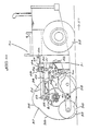
- FIG. 1 A three-sided dual-mass impact roller with its towing tractor is illustrated in side elevation in Figure 1, in which one of the masses has been removed to reveal the components situated between the compactor masses.
- Figure 2 shows a rear view of the impact roller, and
- Figure 3 a plan view thereof.
- the carriage 1 is located between the two compactor masses 2, which are joined together by means of a common axle assembly 3.
- the axle assembly 3 consists of an outer tubular axle and an inner torsion bar, not shown, which keeps the masses rotating synchronously.
- the inner torsion bar is a resilient member in order to allow for a limited amount of twist between the masses.
- the axle assembly 3 is connected by means of a hydraulically controlled linkage system to the carriage 1.
- the linkage system comprises a drag-link 4 fixed at one extremity to the axle 3, and pivotally connected at the other extremity to the upper extremity of a drop-link 5 such that only pitch axis rotation can occur.
- the drop-link is pivotally connected at its lower extremity to the carriage 1 such that only pitch axis rotation can occur and at its upper extremity to a traction device 6 which in practice functions to provide both traction and damping.
- Two pairs of ground engaging wheels 7 are mounted on the carriage. Hydraulic lift cylinders 8 act between the carriage 1 and the axle 3 to lift the compactor masses off the ground when transporting the impact roller.
- the carriage is connected to the towing tractor 10 by means of a universal coupling 9 which allows for relative movement between the tractor and the impact roller about all three axes.
- the coupling 9 allows for roll, yaw and pitch of the impact roller, where “roll” refers to rotational movement of the impact roller about the fore-and-aft direction of travel.
- the compactor masses may typically have three, four or five sided shapes, and together they generally weigh between three and ten tons.
- R and r could typically be 1100mm and 900mm respectively.
- the amount of potential energy stored as the mass rises on to a salient point is stated as M.g.h where h is equal to R-r (in metres) and M is the mass in kilograms.
- M the mass in kilograms.
- the width of the masses shown in Figure 3 would typically be 1 metre and the inter-mass space also 1 metre, the overall width of the machine thus being 3 metres.
- the tractor 10 could weigh 8 tons. From operational experience it is found necessary to have the inter-mass space equal to or less than the width of each mass so that a second compaction pass could position a mass to cover the gap left on the first pass.
- the width of each mass defines also the gap between masses and this requirement restricts the width 12 ( Figures 2 and 3) to a narrow wheelbase.
- Carry mode problems of an impact roller of conventional type will first be described. Referring again to Figures 1, 2 and 3, stability against overturning about the roll axis is dependent entirely on the carriage wheels 7. It will be appreciated that as previously described the carriage is connected though pivots to the drop-link 5 and the drag-link 4 which is finally attached to the axle assembly 3, no relative roll axis movement being permitted between the carriage and the axle.
- the vector lines 16 represent the forces through the centres of gravity of the masses, spaced apart 2m in a typical machine.
- the vector lines 17 represent reaction forces from the tyres, these typically being spaced apart by 0.5m. The adverse ratio of 2.0m to 0.5m arises from the design constraint of having to place the wheels between the pair of masses.
- a practical operational requirement in the use of impact rollers is however that the machine be deployed in the carry mode from one work site to another often several kilometres distant at a reasonable speed, desirably in excess of 20 km/h.
- the undesirable roll axis movements described above however limit the practical carry mode speed to less than 5 km/h for existing dual mass machines.
- Roll axis stability in the carry mode needs to be achieved for a further reason.
- a machine operating in the compaction mode to achieve a number of compaction passes, typically twenty.
- An impact roller compacts in one direction only, therefore at the end of each compaction pass the machine must be turned about to make the return pass.
- the turning movement requires a space of three or four times the overall machine width, which space is often not available.
- the soil surface in the turning area becomes disturbed and uneven, causing the impact roller to slow down with consequent operator discomfort, aggravated wear on the machine and loss of productivity.
- the area in which an impact roller turns is not generally compacted to specification due to the unevenness of coverage.
- One of the objectives of the present invention is to enable the pair of masses to be supported in the carry mode in a sufficiently stable manner that reasonably rapid transport over unmade construction terrain or bituminous surfaced roads is possible, in either a forward or reverse direction with little or no dangerous side to side sway, or damaging ground contact.
- Figures 5 and 6 show that the centre of the mass striking the boulder begins to rise, the axle 3 consequently undergoing a roll axis rotation in the direction of the arrow 15.
- the rare event of striking a boulder 13 is used to explain roll axis displacement.
- differential soil collapse between one side and the other under the impact blows can result similarly in varying degrees of roll axis displacement of the axle.
- there to be a difference in settlement of 50mm between one side and the other creating cyclical roll axis angular displacements such as that indicated by the numeral 15 in Figure 6.
- the time interval in which one side settles relative to the other by an arbitrary figure of 50mm can be approximately 30 milliseconds.
- the roll axis angular displacement described above and illustrated by the arrow 15 in Figure 6 carries with it (referring to Figures 1 and 3) the drag-link 4, the drop-link 5 and the carriage 1. It will be appreciated that large roll axis torque forces and consequent stresses result from transferring this roll axis displacement to the heavy linkage and carriage components occur within the short time interval of typically 30 milliseconds. These short duration roll axis displacements (of the order of 30 ms) are referred to as "shock roll displacements" and the stresses arising therefrom are referred to as shock roll stresses.
- shock stresses requires explanation in relation to the operation of impact rollers.
- 720 000 blows are produced.
- stress repetition of this order of magnitude could produce fatigue failure in the metal components.
- the most important factor in determining the number of stress repetitions which the metal can accommodate before failure occurs is the peak value of the stress pulses.
- shock roll displacements acting against the inertia of heavy carriage components, as previously described. This gives rise to the necessity of providing a central pivot on the axle, by which means shock displacements of typically 2 to 4 degrees of rotation are accommodated and transferred to the heavy carriage components over a sufficiently long time interval to attenuate other wise damaging stresses.
- the machine preferably includes a pair of spaced apart impact compactor masses supported on a common axle connected resiliently to the chassis, with one or more ground engaging wheels mounted to the chassis between the masses.
- the maximum wheel track width defined by the ground engaging wheels of the chassis is preferably approximately equal to or only slightly less than the compaction track width defined by the laterally outer extremities of the two masses.
- the machine in such versions of the invention will also include lifting means, acting between the chassis and the compactor masses, to elevate the compactor masses above the ground for transportation thereof.
- the chassis of the machine is provided by a single, unitary, rigid structure.
- the driven, ground-engaging wheels may be carried by a single drive axle powered by the prime mover.
- the axle supporting the compactor mass or masses has at least a small amount of roll axis freedom relative to the chassis. Damping means are preferably provided to damp roll axis movements of the axle relative to the chassis.
- the chassis of the machine has fore and aft parts articulated to one another at an upright yaw axis.
- Damping means are preferably provided to damp relative roll axis movements of the aft part of the chassis relative to the fore part at least over a predetermined range of pivotal movements about the roll axis.
- the machine may, in this case, include a breakaway mechanism allowing undamped pivotal movement of the aft part relative to the fore in the event of roll axis movement between the parts exceeding a predetermined limit.
- the roll axis damping means may be adjustable to vary the resistance which is offered to relative roll axis movements.
- the damping means In a carry or transportation mode, with the impact compactor masses lifted clear of the ground and hence with a greater propensity to overturning, the damping means will typically provide greater resistance to roll axis movements than in an operative or compaction mode with the impact compactor masses in contact with the ground.
- the damping means preferably provided by hydraulic dampers, may be varied manually while in other cases, there may be automatic control dependent on the operation of steering, braking or other systems of the machine.
- the machine may also include a secondary roll axis pivot, which is designed to take account of shock roll movements and which is typically located at the connection between the axle and a resilient linkage which connects the axle to the chassis.
- the pivot in this case is preferably also damped.
- dampers of rubber or other resilient material provide both the pivoting and damping effects.
- FIGS 8 to 23 illustrate embodiments of the invention, by way of example only. In these Figures:
- FIGS 8 and 9 illustrate the underlying principle of the invention.
- FIGs 8 and 9 show an impact roller chassis frame or carriage 20 which is T-shaped in plan view.
- Steerable wheels 21 are mounted on an axle 22 located beneath the transverse part 20A of the chassis frame.
- the axle 22 may be powered by a suitable motor and transmission located on the transverse part 20A, which can additionally provide seating and controls for an operator.
- a further wheel 23 is mounted in a freely rotatable manner at the end of the web 20B of the T-shaped chassis frame.
- the web of the chassis frame is located between compactor masses 24. It will be noted that the compactor masses are quite closely spaced, this being permitted by the narrowness of the web 20B of the chassis frame.
- the masses 24 are connected to one another for substantially synchronous rotation by a common axle 25.
- Other components (not illustrated) of the linkage between the chassis frame and the compactor masses may be the same as in the conventional linkage previously described with reference to Figures 1 to 3 of the drawings.
- the single wheels 21 and 23 can, in other embodiments of the invention, be replaced by groups of wheels at the relevant locations.
- Figure 9 illustrates a modified chassis frame in which the transverse part 20A of the chassis frame is pivoted to the web 20B of the frame at a vertical axis 27.
- the axle on which the wheels 21 are mounted can be steered as well as driven.
- shock rollaxis displacements of the axle occur, as previously described.
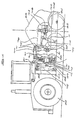
- FIGS. 10 to 14 illustrate a practical, self-powered and steerable embodiment of the invention.
- a soil compaction machine 30 comprising a T-shaped, motorised chassis frame 31 supported upon a pair of driven ground-engaging wheels 32.
- the wheels 32 are located at either extremity of a transverse axle (not visible in the drawings) which is both driven and steerable and which is carried by the transverse part of the T-shaped chassis frame.
- the chassis frame 31 is also supported by tandem pairs of wheels 33 located towards the end of the web part 34 of the chassis frame.
- the web part of the chassis frame 31 is of narrow design with the clear space between the compactor masses being sufficient only to accommodate the web part and the wheels.
- the overall transverse dimension of the driven, steerable axle plus the wheels 32 which it carries is approximately equal to the overall width defined by the compactor masses 35. Thus good anti-roll stability is once again achieved.
- Each compactor mass 35 is a three sided roller with three peripherally spaced salient points 36. Each salient point is followed by a re-entrant portion 37. and each re-entrant portion 37 is followed by a compacting face 38.
- the compactor masses are mounted fast on a common axle 39 in an axle housing 40 so as to rotate in unison when the impact roller moves over the soil surface.
- a pivot point 41 to a rear bulkhead 42 of the chassis frame 31 Pinned at a pivot point 41 to a rear bulkhead 42 of the chassis frame 31 is a generally horizontal drag-link 44 and a vertical link 45.
- the drag link 44 and the vertical link 45 are able to rotate about the pivot point 41 independently of one another.
- An upper extension of the vertical link 45 is pinned at a pivot point 46 to the piston rod of an hydraulic cylinder 47, acting as an hydraulic spring.
- a jack 69 is extended, bringing a plate 71, which is hinged at 72, into contact with the underside of the drag-link 44.
- the drag-link 44 is thereby raised, carrying the axle assembly and compactor masses with it.
- the base of the hydraulic spring 47 which operates in a generally horizontal direction, is pinned to the bulkhead 42 at a pivot point 48.
- the hydraulic spring 47 has an hydraulically actuated ram rod which is connected to a gas charged accumulator (not shown) so as to provide required load deflection characteristics.
- the vertical link 45 is provided with bumper plates 49 adjacent to the central pivot point 41, and rubber bumpers 50 are fixed to the bulkhead 42 opposite the bumper plates 49, so as to provide end-of-travel limit stops for the vertical link 45.
- the rearmost extremity of the drag link 44 is pinned to a drop link 51 at a pivot point 52.
- the upper part of the drop link 51 is pinned at a pivot pint 53 to the rearmost extremity of a spacer bar 54, and the forward extremity of the spacer bar 54 is pinned at a pivot point 55 to the vertical link 45.
- pivot point 55 is located between the pivot points 41 and 46.
- the lower part of the drop link 51 is in the form of a large clevis which straddles the axle housing 40 and which is connected pivotally to the housing 40 at a pivot assembly 56.
- This linkage system constrains the axle housing 40 to move forward and backward relative to the bulkhead 42 without permitting yaw axis freedom, and allows the axle housing 40 to move up and down with freedom to rotate about the roll axis, i.e. about the pivot assembly 56.
- connection between the chassis frame 31 and the compactor masses 35 is resilient in nature.
- the motor and transmission mounted forwardly on the chassis frame 31 operate on the driven wheels 32 to move the machine forward in the direction of the arrow 57 in Figure 10, pulling the compactor masses 35 along by means of the resilient linkage system.
- the compactor masses, in contact with the ground rotate in unison with one another.
- the pivot assembly 56 allows the combined assembly of the two compactor masses 35, the common axle 39 and the axle housing 40 to rotate about the roll axis of the impact roller. This avoids excessive stress on the linkage system.
- the numeral 14 indicates the average ground surface, and as explained previously, the arrow 15 denotes the roll axis movement of the pair of compactor masses as one of them strikes the raised zone or obstruction 13.
- FIGS. 13 and 14 show the details of the pivot assembly 56.
- the tubular axle housing 40 has flat plates 59 let into its sides towards the front and back.
- the lower clevis of the drop link 51 straddles the flat areas defined by the plates 59 and is connected pivotally to the plates by means of pivot pins 60 and bushes 61.
- Spaced apart laterally at the extremities of the drop-link clevis are four restraining pads 62 which act against steel rubbing plates 58 to prevent movement of the axle housing assembly about the yaw axis i.e. about a vertical axis, relative to the chassis frame 31.
- the steel rubbing plates 58 are welded fast to the plates 59.
- the restraining pads 62 which are constructed from nylon material, are adjustable to compensate for wear by means of adjuster screws 63.
- two hydraulic damper cylinders 64 are provided.
- the piston rods of the cylinders 64 are pinned at pivot points 67 to the drag-link 44 and the cylinders themselves are pinned at slotted pivot points 68 to the axle housing 40.
- the two cylinders 64 are connected to a gas-charged hydraulic accumulator 66 via adjustable restriction orifices 70 that allow restricted flow of hydraulic fluid from the cylinders to the accumulator.
- each adjustable orifice 70 Connected in parallel to each adjustable orifice 70 is a non-return valve 65 that allows free flow from the accumulator 66 to the cylinders 64.
- a static position with the axle housing 40 generally parallel to the drag-link 44, the piston rods of the damper cylinders 64 are both in their fully extended position due to the pressure in the accumulator.
- the pistons 75 are situated inside the cylinders at their uppermost limits, and the lower pivot pins are at the lower limit of their travel within the slots at the pivot points 68.
- the hydraulic components function as follows. It is assumed that the right hand side of the axle housing 40, as viewed in Figure 13, is displaced upwardly. Since the cylinder stop pin is already seated at the bottom of the slot 68, the cylinder 64 commences upward movement, being carried by the movement of the axle. Fluid within the cylinder is forced through a hole drilled in the centre of the piston crown 75. Because there is no escape for fluid around the piston crown 75 as a result of the presence of a seal 75a, fluid flows through a port 75b. The non-return valve 65 closes so that fluid flows through the orifice 70, thereby controlling the rate of roll axis movement of the axle housing 40 about the pivot 56.
- the cylinder stop pin remains stationary while the lug on the axle housing 40 with its slot 68 moves downwardly until the upper extremity of the slot engages the stop pin, thereby defining the limit of permitted rotational movement of the axle. Simultaneously, the limit of travel of the right hand piston is reached. Fluid displaced from the right hand cylinder cannot be accommodated in the left hand cylinder as it is already full. The fluid therefore passes into the accumulator 66 which sustains a preset fluid pressure. As soon as the disturbing torque on the axle housing 40 is removed, fluid under pressure flows without restriction through the non-return valve 65 to produce a force between the right hand piston 75 and cylinder 64 which tends to restore parallelism between the draglink and the axle housing 40.
- Sustained fluid pressure from the accumulator 66 operates with both the left and right hand cylinders 64 to provide a self-centring torque between the axle housing 40 and the draglink 44.
- the magnitude of this self-centring torque may be adjusted by operation of the fluid control valve 73 to either drain fluid from the accumulator 66 to the reservoir 74, thereby reducing the fluid pressure, or to charge fluid from the pump 80 to the accumulator, thereby increasing the fluid pressure.
- the machine may be operated in the carry mode with the pair of masses restrained against random roll axis movements. In this way it is possible to achieve safe transportation, at adequate speed, between work sites.
- Figures 10 to 14 thus show an embodiment of the invention based on the integral carriage and steering system shown in Figure 8.
- An application of the invention to the carriage and steering system as shown in Figure 9 will now be described.
- Figure 9 shows a carriage similar to that of Figure 8 but with steering of the drive wheels accomplished by means of a vertical yaw axis pivot 27.
- This is therefore an articulated carriage system.
- Articulated carriage systems are widely used in the construction industry for equipment such as front end loaders, soil compactors and the like.
- In addition to the vertical pivot it is standard practice in such conventional machines to accommodate slow-roll movements due to ground unevenness by providing a roll axis pivot generally allowing limited angular movement.
- two sections of the machine each having stability against overturning during normal operation are coupled together at the combined yaw and roll axis pivot point.
- the part of the carriage indicated by numeral 20B in Figure 9 has intrinsic stability against overturning only when both masses are in contact with the ground, i.e. when operating in the compacting mode.
- the carriage part 20B is unstable about the roll axis. Therefore the roll axis pivot of an articulated type of carriage adapted for dual mass impact rollers requires to have a restraining torque applied to enable the stable wide wheel base part 20A to offer the required resistance to overturning of the part 20B.
- the roll axis restraint should however be such that the degree of restraint may be varied from light torque restraint when the machine is operating in the compaction mode to medium torque restraint when the machine is in the carry mode operating in a straight line, to high torque restraint when the machine is travelling at high speed or when manoeuvring in the carry mode.
- Conditions such as wheels or masses stuck in loose sand, muddy conditions, conditions when the traction wheels are at full torque forwards and backwards, or conditions in which the masses are raised to the carry mode in adverse travel conditions, or any combination of these conditions, would require that the articulation of the roll axis pivot be locked in the vertical orientation to prevent over-toppling of the carriage part 20B or rotation of the part 20A about its wheel axis.
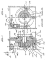
- Figure 15 shows an elevation with one mass removed, and partly sectioned, to show the construction of the machine parts.
- Figure 16 shows a plan view, partly sectioned, of the machine seen in Figure 15.
- the motorised chassis 80 of the articulated machine is coupled by a generally vertical pivot system 86 to a trailing carriage 81 including a carriage extension 84 which is sufficiently narrow to allow a set of carriage wheels 83 to be fitted in the space between the compactor masses 85.
- Drive wheels 82 are mounted to the tractor chassis 80. Steering of the machine is effected by operating steering jacks 87.
- Between the chassis 80 and the carriage 81 is a pivot housing 89 within which are located the roll axis and yaw axis pivots and control mechanisms.
- a pivot shaft 88 which is flanged and secured to the carriage 81 by bolts 90 and which protrudes through a machined hole in the pivot housing 89, carries a pivot bearing 91 and a thrust bearing 92 which reacts against a thrust bearing 93 located in an annular groove in the mating face of the pivot housing 89.
- a flange 94 is secured to the pivot shaft to retain and pre-load the thrust bearing.
- the flange carries crank-pins 95 by means of which rotational torque is applied to the pivot shaft 88 by the operation of a pair of hydraulic rams 96.
- the internal mechanisms of the pivot housing 89 are shown (with some detail omitted) in Figures 15 and 16. Detail is shown to a larger scale in Figures 17 and 18 which also illustrate a break-away safety system.
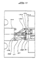
- Figure 17 shows a detail of the pivot system connecting the carriage 81 to the pivot housing 89. Numerals correspond with those in Figures 15 and 16, but additional numerals are incorporated to show detailed features.
- Figure 18 shows cross-sections at the lines A-A and B-B in Figure 17.
- the flange 94 in Figure 17 is fixed against rotation by a key 122 engaging the pivot shaft 88, and retains the pivot and thrust bearings 91 and 92. Preload on the thrust bearings 92 and 93 is achieved by fastening screws 124 passing through a retainer washer 120 into the pivot shaft 88.
- a crank flange 121 is enabled, by bearings 123, to rotate relative to the flange 94, but during normal operation of the machine is constrained to follow the random clockwise and counter-clockwise movements of the flange 94 by location of a pre-loaded, vee-shaped pin 126 in a corresponding detent.
- the pin 126 includes an hydraulic cylinder, of which the vee-shaped element is the piston rod. Note that these random movements occur when the chassis 81 moves about the roll axis relative to the pivot housing 89, but during normal operation stay within a range of about 15 degrees on either side of the vertical.
- crank pins 95 are pivotally attached to the piston rods 127 of the cylinders 96.
- operation of hydraulic pressure at a port 128 applies a force to the piston rod 127 equal to the cross sectional area of the rod piston multiplied by the hydraulic pressure.
- the cylinder 96 is thereby extended to cause a hinge plate 129 to bear against a stop block 130.
- the lengths of the piston rods 127 are selected such that with both pistons extended to the extremity of their travel, the carriage 81 is in correct vertical alignment with the pivot housing 89, and the pin 126 is seated in its corresponding detent in the flange 94.
- the flange 94 carries with it the crank flange 121, which in turn forces (say) the left-hand piston rod 127 into the cylinder 96 with a damping action controlled by the setting of a variable restrictor valve 131.
- the crank pin 95 draws the piston rod and cylinder downwardly, the top end of the cylinder carrying with it, without restraint, the right hand hinge plate 129.
- the hydraulic pressure in the left hand cylinder will tend to cause the cylinder assembly to extend to its full extension, and in this manner the carriage 81 and the pivot housing 89 are biased by a pre-set torque to be in alignment over the arc of allowed travel, in this case 30°.
- the pre-set torque may be adjusted by varying the hydraulic pressure applied to the system, and the damping may be adjusted by varying the setting of the restrictor valve 131.
- the hydraulic pressure at the port 132 can be varied in order to adjust the pre-load upon the pin 126, and a hydraulic pressure relief valve may be provided in this circuit to vent fluid to tank as the pin 126 moves into its cylinder or the excess fluid may be accommodated in a pressurised hydraulic accumulator.
- a linkage system consisting of a drag-link 98, a drop-link 99 and a traction spring 97.
- the traction spring 97 is hydraulically operated to provide a nearly constant traction force whatever the amount of piston rod extension.
- bumper plates 101 are provided to operate against travel limiting bumpers 100, preferably constructed of hard rubber.
- a pivot 102 provides pitch axis rotation of the drop-link 99 relative to the carriage 81
- a pivot 103 provides pitch axis rotation of the drag-link 98 relative to the drop-link 99.
- any roll axis displacement of the axle housing 105 would induce the carriage 81 to follow the roll axis displacement and rotate about the pivot shaft 88.
- Figure 19 shows partly a side elevation and partly a cross-section at the longitudinal centreline of the machine.
- Figure 20 shows an end elevation and Figure 21 a plan view of the axle housing 105 with the drag-link removed to show the position and orientation of the rubber elements 107 and 108.
- These rubber elements in the form of rubber pads, are able to resist compressive loads on their large area dimension with only slight deflection, typically of the order of 10% of the pad thickness. Their lateral dimension is designed to allow for shear deflections of typically 50% of the pad thickness.
- the drag-link 104 For ease of assembly between the drag-link 104 and the axle housing 105, provision is made for bonding the pads 107 and 108 to the axle housing structure.
- the drag-link 104 is assembled over the axle housing to restrain the pads 108, with a clearance between the shear pads 107 and opposing compressor plates 113. Screws 115 are then tightened to pre-load the shear pads 107, and screws 116 are tightened to pre-load the compression pads 108.
- the vertical or yaw articulation axis is between the top and bottom ball joints 135.
- a top link 136 of the yaw pivot system is also pivoted at the carriage end by means of a ball joint 137.
- the link 136 can be constrained to be in line with the longitudinal axis of the carriage by applying hydraulic pressure to rams 138, in which case there would be no roll axis freedom between the carriage 81 and the motorised chassis 80.
- By reducing the hydraulic pressure on the two rams 138 sideways movement is permitted in response to a pre-set side force on the link 136 at the pivot point 137.
- the cylinders of the rams 138 are pivotally connected to a lever arm 139 so that when each ram-rod is fully extended, the lever abuts against a stop 140 which is adjustable for position by means of a screw 140A.
- Steering of the articulated machine of Figures 22 and 23 is by operation of steering jacks 141.
- the self-propelled impact compaction machines described above have a number of important features, including the following:
Landscapes
- Engineering & Computer Science (AREA)
- Structural Engineering (AREA)
- Life Sciences & Earth Sciences (AREA)
- Civil Engineering (AREA)
- Environmental & Geological Engineering (AREA)
- Agronomy & Crop Science (AREA)
- Architecture (AREA)
- Soil Sciences (AREA)
- General Life Sciences & Earth Sciences (AREA)
- Mining & Mineral Resources (AREA)
- Paleontology (AREA)
- General Engineering & Computer Science (AREA)
- Road Paving Machines (AREA)
- Investigation Of Foundation Soil And Reinforcement Of Foundation Soil By Compacting Or Drainage (AREA)
Description
- Figure 1
- shows a side elevation of a conventional towed impact roller, with one compactor mass removed to show details of the carriage and linkage system;
- Figure 2
- shows a rear elevation of the impact roller seen in Figure 1;
- Figure 3
- shows a plan view of the impact roller seen in Figure 1;
- Figure 4
- shows a diagrammatic representation of the measurements required for the determination of the drop height of an impact roller;
- Figure 5
- shows a diagrammatic side elevation of a pair of compactor masses striking an uneven site surface;
- Figure 6
- shows a diagrammatic rear elevation of a pair of compactor masses striking an uneven site surface, and indicates the direction of angular acceleration of the compactor masses and connecting axle assembly; and
- Figure 7
- shows a diagrammatic representation of the weight distribution of a pair of compactor masses in the carrying position supported by a pair of narrowly spaced wheels, and illustrates instability when travelling over uneven ground.
- Figure 8
- shows a diagrammatic plan view of a rigid T- shaped chassis frame of an impact roller with drive-steer axle, in accordance with the principles of the invention;
- Figure 9
- shows a diagrammatic plan view of a T-shaped chassis frame with the articulated system of steering;
- Figure 10
- shows a partly sectioned side elevation of an impact roller according to the invention, one compactor mass being removed so as to expose the working mechanism and chassis details;
- Figure 11
- shows a plan view of the machine seen in Figure 10, with certain details omitted in the interests of clarity;
- Figure 12
- shows a rear elevation of the machine seen in Figure 10, with certain details omitted in the interests of clarity;
- Figure 13
- shows a partly sectioned rear view of the roll axis pivot seen in Figure 10;
- Figure 14
- shows a sectional view of the mechanism seen in Figure 13;
- Figure 15
- shows a partly sectioned side elevation of an impact roller according to an alternative embodiment of the invention;
- Figure 16
- shows a plan view of the impact roller seen in Figure 15;
- Figure 17
- shows a sectioned view, on an enlarged scale, of the pivot and restraining mechanism of the impact roller shown in Figures 15 and 16;
- Figure 18
- shows an elevation and part sectioned view of the mechanism of Figure 17;
- Figure 19
- shows, to an enlarged scale, details of the drag-link and elasticised shock roll axis stress attenuation and orientation mechanism seen in Figure 15;
- Figure 20
- shows an end elevation of the mechanism seen in Figure 19;
- Figure 21
- shows a plan view of the axle tube of Figure 19 indicating the positioning of the elastic elements;
- Figure 22
- shows in side elevation a further alternative embodiment of the invention; and
- Figure 23
- shows, in plan view, a detail of the pivot mechanism seen in Figure 22.
Claims (16)
- A self-propelled impact compaction machine comprising:a chassis,a prime mover on a forward part of the chassis,ground engaging wheels on the forward part of the chassis at least some of which are driven by the prime mover and which define a maximum wheel track width,laterally spaced impact compactor masses located on opposite sides of a rearward part of the chassis which is supported on ground-engaging wheels between the impact compactor masses, the impact compactor masses defining a compaction track width, measured from one lateral extremity to the opposite lateral extremity of the masses, and being connected to one another for synchronous rotation by a common axle which is connected resiliently to the chassis and capable of at least limited roll axis pivotal movement relative to the chassis about a fore-and-aft roll axis, and the impact compactor masses defining a compaction track width which is not substantially different from the wheel track width defined by the ground engaging wheels of the forward part of the chassis;lifting and lowering means operable to raise the impact compactor masses off the ground when the impact compaction machine is in a carry mode and to lower the impact compaction masses into contact with the ground when the impact compaction machine is in a soil compaction mode;roll axis damping means which operates to restrain roll axis movements of the axle relative to the chassis and to restore the axle to a stable orientation relative to the chassis, thereby to stabilise the impact compaction machine in the carry mode.
- A self-propelled impact compaction machine according to claim 1 wherein the maximum wheel track width defined by the ground engaging wheels of the forward part of the chassis is approximately equal to, or only slightly less than, the compaction track width defined by the laterally outer extremities of the impact compactor masses.
- A self-propelled impact compaction machine according to claim 1 or claim 2 wherein the forward and rearward parts of the chassis define a T-shape in plan view.
- A self-propelled impact compaction machine according to claim 2 or claim 3 wherein the driven, ground-engaging wheels of the forward part of the chassis are carried by a single drive axle powered by the prime mover.
- A self-propelled impact compaction machine according to any one of the preceding claims wherein the forward and rearward parts of the chassis are connected to one another in a manner allowing no yawing movements of the rearward part relative to the forward part.
- A self-propelled impact compaction machine according to claim 5 comprising hydraulic damping cylinders operating to damp roll axis movements of the axle relative to the chassis.
- A self-propelled impact compaction machine according to claim 6 wherein the hydraulic damping cylinders are controlled by a gas accumulator.
- A self-propelled impact compaction machine according to any one of claims 1 to 4 wherein forward and rearward parts of the chassis are articulated to one another at an upright yaw axis pivot.
- A self-propelled impact compaction machine according to claim 8 and comprising a roll axis pivot between the forward and rearward chassis parts.
- A self-propelled impact compaction machine according to claim 9 and comprising further roll axis damping means to restrain roll axis movements of the rearward part of the chassis relative to the forward part of the chassis at least over a predetermined range of pivotal movement about the roll axis pivot.
- A self-propelled impact compaction machine according to claim 10 and comprising a breakaway mechanism allowing undamped pivotal movement of the rearward part of the chassis relative to the forward part of the chassis in the event of roll axis movement between the parts, about the roll axis pivot, exceeding a predetermined limit.
- A self-propelled impact compaction machine according to either one of claims 10 or 11 wherein the further roll axis damping means is adjustable to vary the restraint offered to relative roll axis movements between the parts.
- A self-propelled impact compaction machine according to claim 12 wherein the further roll axis damping means provides greater resistance to roll axis movements when the machine is in the carry mode than when the machine is in the compaction mode.
- A self-propelled impact compaction machine according to either one of claims 12 or 13 comprising control means operating, in dependence on the operation of steering, braking or other systems of the machine, to control the level of restraint offered by the further damping means to roll axis movements about the roll axis pivot.
- A self-propelled impact compaction machine according to any one of claims 8 to 14 wherein the roll axis damping means which operates to restrain roll axis movements of the axle relative :o the chassis and to restore the axle to a stable orientation relative to the chassis comprises dampers made of resilient material which act between the axle and a drag link forming part of the resilient connection between the axle and the chassis.
- A self-propelled impact compaction machine according to claim 15 wherein at least some of the dampers act in shear to restrain roll axis movements of the axle relative to the chassis.
Applications Claiming Priority (3)
| Application Number | Priority Date | Filing Date | Title |
|---|---|---|---|
| GBGB9514583.5A GB9514583D0 (en) | 1995-07-17 | 1995-07-17 | Soil compactor with stabilising wheel system |
| GB9514583 | 1995-07-17 | ||
| PCT/GB1996/001708 WO1997004179A1 (en) | 1995-07-17 | 1996-07-17 | Soil compactor with stabilising wheel system |
Publications (2)
| Publication Number | Publication Date |
|---|---|
| EP0839233A1 EP0839233A1 (en) | 1998-05-06 |
| EP0839233B1 true EP0839233B1 (en) | 2002-10-09 |
Family
ID=10777793
Family Applications (1)
| Application Number | Title | Priority Date | Filing Date |
|---|---|---|---|
| EP96924977A Expired - Lifetime EP0839233B1 (en) | 1995-07-17 | 1996-07-17 | Soil compactor with stabilising wheel system |
Country Status (9)
| Country | Link |
|---|---|
| EP (1) | EP0839233B1 (en) |
| JP (1) | JP2000501797A (en) |
| CN (1) | CN1143031C (en) |
| AU (1) | AU703060B2 (en) |
| CA (1) | CA2227068C (en) |
| DE (1) | DE69624244T2 (en) |
| GB (1) | GB9514583D0 (en) |
| WO (1) | WO1997004179A1 (en) |
| ZA (1) | ZA966036B (en) |
Families Citing this family (8)
| Publication number | Priority date | Publication date | Assignee | Title |
|---|---|---|---|---|
| WO1999060218A1 (en) * | 1998-05-21 | 1999-11-25 | Compaction Technology (Soil) Limited | Soil compaction machine |
| EP1131495B1 (en) | 1998-11-09 | 2004-02-25 | Compaction Technology (Soil) Limited | Compaction roller |
| EP1111134A3 (en) * | 1999-12-22 | 2003-10-01 | Hamm AG | Road roller |
| WO2014162261A1 (en) * | 2013-04-02 | 2014-10-09 | Roger Arnold Stromsoe | A soil compaction system and method |
| EP3247837A2 (en) * | 2015-01-21 | 2017-11-29 | Roger Arnold Stromsoe | An impact compactor, compaction system and a method of obtaining soil strength |
| CA2999808C (en) * | 2015-09-25 | 2019-06-04 | Roger Arnold Stromsoe | Impact compactor |
| CN110946042A (en) * | 2019-11-15 | 2020-04-03 | 华艺生态园林股份有限公司 | Self-propelled mutual compensation lawn compactor |
| RU200537U1 (en) * | 2020-06-08 | 2020-10-28 | федеральное государственное бюджетное образовательное учреждение высшего образования "Южно-Российский государственный политехнический университет (НПИ) имени М.И. Платова" | Traction and braking device of the road roller |
Family Cites Families (4)
| Publication number | Priority date | Publication date | Assignee | Title |
|---|---|---|---|---|
| US3477535A (en) * | 1967-03-10 | 1969-11-11 | Case Co J I | Roller attachment for a self-propelled vehicle |
| DE2359375C2 (en) * | 1973-11-28 | 1984-06-14 | South African Inventions Development Corp., Pretoria, Transvaal | Compaction roller with a non-circular roller drum |
| GB1583425A (en) * | 1977-05-25 | 1981-01-28 | South African Inventions | Method of operating a compaction roller assembly and a compaction roller assembly |
| US4422795A (en) * | 1979-04-09 | 1983-12-27 | Berrange Aubrey R | Compactor |
-
1995
- 1995-07-17 GB GBGB9514583.5A patent/GB9514583D0/en active Pending
-
1996
- 1996-07-16 ZA ZA9606036A patent/ZA966036B/en unknown
- 1996-07-17 JP JP9506422A patent/JP2000501797A/en active Pending
- 1996-07-17 EP EP96924977A patent/EP0839233B1/en not_active Expired - Lifetime
- 1996-07-17 WO PCT/GB1996/001708 patent/WO1997004179A1/en active IP Right Grant
- 1996-07-17 DE DE69624244T patent/DE69624244T2/en not_active Expired - Fee Related
- 1996-07-17 CN CNB961967900A patent/CN1143031C/en not_active Expired - Fee Related
- 1996-07-17 CA CA002227068A patent/CA2227068C/en not_active Expired - Fee Related
- 1996-07-17 AU AU65243/96A patent/AU703060B2/en not_active Ceased
Also Published As
| Publication number | Publication date |
|---|---|
| CA2227068C (en) | 2004-09-28 |
| AU703060B2 (en) | 1999-03-11 |
| JP2000501797A (en) | 2000-02-15 |
| DE69624244D1 (en) | 2002-11-14 |
| AU6524396A (en) | 1997-02-18 |
| WO1997004179A1 (en) | 1997-02-06 |
| EP0839233A1 (en) | 1998-05-06 |
| CN1143031C (en) | 2004-03-24 |
| DE69624244T2 (en) | 2003-06-18 |
| CN1195383A (en) | 1998-10-07 |
| CA2227068A1 (en) | 1997-02-06 |
| GB9514583D0 (en) | 1995-09-13 |
| ZA966036B (en) | 1998-01-16 |
Similar Documents
| Publication | Publication Date | Title |
|---|---|---|
| RU2607932C2 (en) | Two caterpillar tractor | |
| US6164399A (en) | Track-type carriage system for heavy vehicles | |
| US4422795A (en) | Compactor | |
| US4147448A (en) | Method of operating a compaction roller assembly, and a compaction roller assembly | |
| US20010024021A1 (en) | Working apparatus | |
| US2909106A (en) | Impact rolling or tamping machines for the compaction of loose materials, such as road surfaces | |
| EP0839233B1 (en) | Soil compactor with stabilising wheel system | |
| US4324417A (en) | Vehicle with bogie-mounted wheels and raising device for a pair of wheels | |
| WO1997013924A1 (en) | Soil levelling device | |
| GB2311967A (en) | A variable-track, four wheel steering agricultural vehicle with active suspension | |
| CA1272376A (en) | Improved running gear suspension for articulated construction vehicles | |
| US4552238A (en) | Tractor scraper hitch steering and suspension system | |
| US2321833A (en) | Motor vehicle underbody truck grader | |
| GB2358839A (en) | Working apparatus | |
| CA1065914A (en) | Roll stiffening and dampening in articulated vehicles | |
| EP0839232B1 (en) | Compaction of soil | |
| US4149606A (en) | Wheel tractor suspension system | |
| EP0494286A1 (en) | Vehicle. | |
| US2891331A (en) | Transport dolly | |
| US2665622A (en) | Tractor borne agricultural implement and hitch therefor | |
| US2950926A (en) | Retractable auxiliary wheels | |
| CA1107785A (en) | Vehicle axle suspension system | |
| GB1583425A (en) | Method of operating a compaction roller assembly and a compaction roller assembly | |
| JPH0115650B2 (en) | ||
| WO2005072368A2 (en) | Landfill compactor |
Legal Events
| Date | Code | Title | Description |
|---|---|---|---|
| PUAI | Public reference made under article 153(3) epc to a published international application that has entered the european phase |
Free format text: ORIGINAL CODE: 0009012 |
|
| 17P | Request for examination filed |
Effective date: 19980128 |
|
| AK | Designated contracting states |
Kind code of ref document: A1 Designated state(s): BE DE ES FR GB IT NL SE |
|
| REG | Reference to a national code |
Ref country code: GB Ref legal event code: 712F |
|
| 19A | Proceedings stayed before grant |
Effective date: 19980513 |
|
| REG | Reference to a national code |
Ref country code: GB Ref legal event code: 712F |
|
| REG | Reference to a national code |
Ref country code: GB Ref legal event code: 712G |
|
| REG | Reference to a national code |
Ref country code: GB Ref legal event code: 712G |
|
| 19F | Resumption of proceedings before grant (after stay of proceedings) |
Effective date: 20010529 |
|
| RAP1 | Party data changed (applicant data changed or rights of an application transferred) |
Owner name: BERRANGE, AUBREY RALPH |
|
| GRAG | Despatch of communication of intention to grant |
Free format text: ORIGINAL CODE: EPIDOS AGRA |
|
| 17Q | First examination report despatched |
Effective date: 20011126 |
|
| GRAG | Despatch of communication of intention to grant |
Free format text: ORIGINAL CODE: EPIDOS AGRA |
|
| GRAH | Despatch of communication of intention to grant a patent |
Free format text: ORIGINAL CODE: EPIDOS IGRA |
|
| GRAH | Despatch of communication of intention to grant a patent |
Free format text: ORIGINAL CODE: EPIDOS IGRA |
|
| GRAA | (expected) grant |
Free format text: ORIGINAL CODE: 0009210 |
|
| AK | Designated contracting states |
Kind code of ref document: B1 Designated state(s): BE DE ES FR GB IT NL SE |
|
| PG25 | Lapsed in a contracting state [announced via postgrant information from national office to epo] |
Ref country code: NL Free format text: LAPSE BECAUSE OF FAILURE TO SUBMIT A TRANSLATION OF THE DESCRIPTION OR TO PAY THE FEE WITHIN THE PRESCRIBED TIME-LIMIT Effective date: 20021009 Ref country code: IT Free format text: LAPSE BECAUSE OF FAILURE TO SUBMIT A TRANSLATION OF THE DESCRIPTION OR TO PAY THE FEE WITHIN THE PRESCRIBED TIME-LIMIT;WARNING: LAPSES OF ITALIAN PATENTS WITH EFFECTIVE DATE BEFORE 2007 MAY HAVE OCCURRED AT ANY TIME BEFORE 2007. THE CORRECT EFFECTIVE DATE MAY BE DIFFERENT FROM THE ONE RECORDED. Effective date: 20021009 Ref country code: FR Free format text: LAPSE BECAUSE OF FAILURE TO SUBMIT A TRANSLATION OF THE DESCRIPTION OR TO PAY THE FEE WITHIN THE PRESCRIBED TIME-LIMIT Effective date: 20021009 Ref country code: BE Free format text: LAPSE BECAUSE OF FAILURE TO SUBMIT A TRANSLATION OF THE DESCRIPTION OR TO PAY THE FEE WITHIN THE PRESCRIBED TIME-LIMIT Effective date: 20021009 |
|
| REG | Reference to a national code |
Ref country code: GB Ref legal event code: FG4D |
|
| REF | Corresponds to: |
Ref document number: 69624244 Country of ref document: DE Date of ref document: 20021114 |
|
| RAP2 | Party data changed (patent owner data changed or rights of a patent transferred) |
Owner name: MARTEC LIMITED |
|
| PG25 | Lapsed in a contracting state [announced via postgrant information from national office to epo] |
Ref country code: SE Free format text: LAPSE BECAUSE OF FAILURE TO SUBMIT A TRANSLATION OF THE DESCRIPTION OR TO PAY THE FEE WITHIN THE PRESCRIBED TIME-LIMIT Effective date: 20030109 |
|
| NLT2 | Nl: modifications (of names), taken from the european patent patent bulletin |
Owner name: MARTEC LIMITED |
|
| NLV1 | Nl: lapsed or annulled due to failure to fulfill the requirements of art. 29p and 29m of the patents act | ||
| PG25 | Lapsed in a contracting state [announced via postgrant information from national office to epo] |
Ref country code: ES Free format text: LAPSE BECAUSE OF FAILURE TO SUBMIT A TRANSLATION OF THE DESCRIPTION OR TO PAY THE FEE WITHIN THE PRESCRIBED TIME-LIMIT Effective date: 20030429 |
|
| EN | Fr: translation not filed | ||
| PLBE | No opposition filed within time limit |
Free format text: ORIGINAL CODE: 0009261 |
|
| STAA | Information on the status of an ep patent application or granted ep patent |
Free format text: STATUS: NO OPPOSITION FILED WITHIN TIME LIMIT |
|
| 26N | No opposition filed |
Effective date: 20030710 |
|
| PGFP | Annual fee paid to national office [announced via postgrant information from national office to epo] |
Ref country code: DE Payment date: 20080728 Year of fee payment: 13 |
|
| PGFP | Annual fee paid to national office [announced via postgrant information from national office to epo] |
Ref country code: GB Payment date: 20080728 Year of fee payment: 13 |
|
| GBPC | Gb: european patent ceased through non-payment of renewal fee |
Effective date: 20090717 |
|
| PG25 | Lapsed in a contracting state [announced via postgrant information from national office to epo] |
Ref country code: GB Free format text: LAPSE BECAUSE OF NON-PAYMENT OF DUE FEES Effective date: 20090717 |
|
| PG25 | Lapsed in a contracting state [announced via postgrant information from national office to epo] |
Ref country code: DE Free format text: LAPSE BECAUSE OF NON-PAYMENT OF DUE FEES Effective date: 20100202 |