EP0837743B1 - Improved fluoropolymer adhesion - Google Patents
Improved fluoropolymer adhesion Download PDFInfo
- Publication number
- EP0837743B1 EP0837743B1 EP96926710A EP96926710A EP0837743B1 EP 0837743 B1 EP0837743 B1 EP 0837743B1 EP 96926710 A EP96926710 A EP 96926710A EP 96926710 A EP96926710 A EP 96926710A EP 0837743 B1 EP0837743 B1 EP 0837743B1
- Authority
- EP
- European Patent Office
- Prior art keywords
- tetrafluoroethylene
- inorganic compound
- fluorochemical
- copolymer
- composite
- Prior art date
- Legal status (The legal status is an assumption and is not a legal conclusion. Google has not performed a legal analysis and makes no representation as to the accuracy of the status listed.)
- Expired - Lifetime
Links
- 229920002313 fluoropolymer Polymers 0.000 title description 19
- 239000004811 fluoropolymer Substances 0.000 title description 17
- 229910010272 inorganic material Inorganic materials 0.000 claims description 46
- 150000002484 inorganic compounds Chemical class 0.000 claims description 44
- 239000000843 powder Substances 0.000 claims description 35
- 239000002131 composite material Substances 0.000 claims description 34
- 238000000034 method Methods 0.000 claims description 31
- 230000008569 process Effects 0.000 claims description 24
- 229920001577 copolymer Polymers 0.000 claims description 22
- -1 poly(acrylic acid) Polymers 0.000 claims description 22
- 239000001344 [(2S,3S,4R,5R)-4-acetyloxy-2,5-bis(acetyloxymethyl)-2-[(2R,3R,4S,5R,6R)-3,4,5-triacetyloxy-6-(acetyloxymethyl)oxan-2-yl]oxyoxolan-3-yl] acetate Substances 0.000 claims description 18
- 229940013883 sucrose octaacetate Drugs 0.000 claims description 18
- ZIJKGAXBCRWEOL-SAXBRCJISA-N Sucrose octaacetate Chemical compound CC(=O)O[C@H]1[C@H](OC(C)=O)[C@@H](COC(=O)C)O[C@@]1(COC(C)=O)O[C@@H]1[C@H](OC(C)=O)[C@@H](OC(C)=O)[C@H](OC(C)=O)[C@@H](COC(C)=O)O1 ZIJKGAXBCRWEOL-SAXBRCJISA-N 0.000 claims description 17
- 239000002318 adhesion promoter Substances 0.000 claims description 16
- 239000007787 solid Substances 0.000 claims description 10
- OKTJSMMVPCPJKN-UHFFFAOYSA-N Carbon Chemical compound [C] OKTJSMMVPCPJKN-UHFFFAOYSA-N 0.000 claims description 9
- 229910052799 carbon Inorganic materials 0.000 claims description 9
- PNEYBMLMFCGWSK-UHFFFAOYSA-N aluminium oxide Inorganic materials [O-2].[O-2].[O-2].[Al+3].[Al+3] PNEYBMLMFCGWSK-UHFFFAOYSA-N 0.000 claims description 8
- VYPSYNLAJGMNEJ-UHFFFAOYSA-N Silicium dioxide Chemical compound O=[Si]=O VYPSYNLAJGMNEJ-UHFFFAOYSA-N 0.000 claims description 7
- 229920000840 ethylene tetrafluoroethylene copolymer Polymers 0.000 claims description 7
- 238000010438 heat treatment Methods 0.000 claims description 7
- 229920001897 terpolymer Polymers 0.000 claims description 7
- 229920001774 Perfluoroether Polymers 0.000 claims description 6
- GWEVSGVZZGPLCZ-UHFFFAOYSA-N Titan oxide Chemical compound O=[Ti]=O GWEVSGVZZGPLCZ-UHFFFAOYSA-N 0.000 claims description 6
- MCMNRKCIXSYSNV-UHFFFAOYSA-N Zirconium dioxide Chemical compound O=[Zr]=O MCMNRKCIXSYSNV-UHFFFAOYSA-N 0.000 claims description 6
- BTXXTMOWISPQSJ-UHFFFAOYSA-N 4,4,4-trifluorobutan-2-one Chemical compound CC(=O)CC(F)(F)F BTXXTMOWISPQSJ-UHFFFAOYSA-N 0.000 claims description 5
- BQACOLQNOUYJCE-FYZZASKESA-N Abietic acid Natural products CC(C)C1=CC2=CC[C@]3(C)[C@](C)(CCC[C@@]3(C)C(=O)O)[C@H]2CC1 BQACOLQNOUYJCE-FYZZASKESA-N 0.000 claims description 5
- RSWGJHLUYNHPMX-UHFFFAOYSA-N Abietic-Saeure Natural products C12CCC(C(C)C)=CC2=CCC2C1(C)CCCC2(C)C(O)=O RSWGJHLUYNHPMX-UHFFFAOYSA-N 0.000 claims description 5
- 229920002125 Sokalan® Polymers 0.000 claims description 5
- 229920001343 polytetrafluoroethylene Polymers 0.000 claims description 5
- CZMRCDWAGMRECN-UGDNZRGBSA-N Sucrose Chemical compound O[C@H]1[C@H](O)[C@@H](CO)O[C@@]1(CO)O[C@@H]1[C@H](O)[C@@H](O)[C@H](O)[C@@H](CO)O1 CZMRCDWAGMRECN-UGDNZRGBSA-N 0.000 claims description 4
- 229930006000 Sucrose Natural products 0.000 claims description 4
- 239000005720 sucrose Substances 0.000 claims description 4
- 229910052580 B4C Inorganic materials 0.000 claims description 3
- INAHAJYZKVIDIZ-UHFFFAOYSA-N boron carbide Chemical compound B12B3B4C32B41 INAHAJYZKVIDIZ-UHFFFAOYSA-N 0.000 claims description 3
- PMHQVHHXPFUNSP-UHFFFAOYSA-M copper(1+);methylsulfanylmethane;bromide Chemical compound Br[Cu].CSC PMHQVHHXPFUNSP-UHFFFAOYSA-M 0.000 claims description 3
- 125000002573 ethenylidene group Chemical group [*]=C=C([H])[H] 0.000 claims description 3
- 239000000178 monomer Substances 0.000 claims description 3
- 229920002981 polyvinylidene fluoride Polymers 0.000 claims description 3
- 239000005368 silicate glass Substances 0.000 claims description 3
- HBMJWWWQQXIZIP-UHFFFAOYSA-N silicon carbide Chemical compound [Si+]#[C-] HBMJWWWQQXIZIP-UHFFFAOYSA-N 0.000 claims description 3
- 229910010271 silicon carbide Inorganic materials 0.000 claims description 3
- 239000000377 silicon dioxide Substances 0.000 claims description 3
- TWNQGVIAIRXVLR-UHFFFAOYSA-N oxo(oxoalumanyloxy)alumane Chemical compound O=[Al]O[Al]=O TWNQGVIAIRXVLR-UHFFFAOYSA-N 0.000 description 32
- 239000000945 filler Substances 0.000 description 30
- 239000000463 material Substances 0.000 description 29
- 239000011159 matrix material Substances 0.000 description 18
- 229920006362 Teflon® Polymers 0.000 description 17
- 239000002245 particle Substances 0.000 description 15
- 238000003475 lamination Methods 0.000 description 12
- RZVAJINKPMORJF-UHFFFAOYSA-N Acetaminophen Chemical compound CC(=O)NC1=CC=C(O)C=C1 RZVAJINKPMORJF-UHFFFAOYSA-N 0.000 description 11
- KFZMGEQAYNKOFK-UHFFFAOYSA-N Isopropanol Chemical compound CC(C)O KFZMGEQAYNKOFK-UHFFFAOYSA-N 0.000 description 11
- 239000000203 mixture Substances 0.000 description 11
- 239000005297 pyrex Substances 0.000 description 11
- 229910052809 inorganic oxide Inorganic materials 0.000 description 10
- 239000011248 coating agent Substances 0.000 description 9
- 230000000052 comparative effect Effects 0.000 description 9
- 229920003223 poly(pyromellitimide-1,4-diphenyl ether) Polymers 0.000 description 9
- 239000000243 solution Substances 0.000 description 9
- 238000000576 coating method Methods 0.000 description 8
- 239000000758 substrate Substances 0.000 description 8
- 229910000831 Steel Inorganic materials 0.000 description 6
- 239000010959 steel Substances 0.000 description 6
- 229920006355 Tefzel Polymers 0.000 description 5
- QHSJIZLJUFMIFP-UHFFFAOYSA-N ethene;1,1,2,2-tetrafluoroethene Chemical compound C=C.FC(F)=C(F)F QHSJIZLJUFMIFP-UHFFFAOYSA-N 0.000 description 5
- 230000006872 improvement Effects 0.000 description 5
- 229920000642 polymer Polymers 0.000 description 5
- 238000003825 pressing Methods 0.000 description 5
- IJGRMHOSHXDMSA-UHFFFAOYSA-N Atomic nitrogen Chemical compound N#N IJGRMHOSHXDMSA-UHFFFAOYSA-N 0.000 description 4
- 239000004812 Fluorinated ethylene propylene Substances 0.000 description 4
- 230000032798 delamination Effects 0.000 description 4
- 238000006073 displacement reaction Methods 0.000 description 4
- 238000011068 loading method Methods 0.000 description 4
- 238000002156 mixing Methods 0.000 description 4
- 229920009441 perflouroethylene propylene Polymers 0.000 description 4
- 238000012545 processing Methods 0.000 description 4
- 239000002904 solvent Substances 0.000 description 4
- 239000000126 substance Substances 0.000 description 4
- XLYOFNOQVPJJNP-UHFFFAOYSA-N water Substances O XLYOFNOQVPJJNP-UHFFFAOYSA-N 0.000 description 4
- 239000003082 abrasive agent Substances 0.000 description 3
- 239000000853 adhesive Substances 0.000 description 3
- 230000001070 adhesive effect Effects 0.000 description 3
- 238000013329 compounding Methods 0.000 description 3
- 239000011231 conductive filler Substances 0.000 description 3
- 230000007423 decrease Effects 0.000 description 3
- 238000009826 distribution Methods 0.000 description 3
- 239000011521 glass Substances 0.000 description 3
- 230000001737 promoting effect Effects 0.000 description 3
- QTBSBXVTEAMEQO-UHFFFAOYSA-M Acetate Chemical compound CC([O-])=O QTBSBXVTEAMEQO-UHFFFAOYSA-M 0.000 description 2
- QGZKDVFQNNGYKY-UHFFFAOYSA-N Ammonia Chemical compound N QGZKDVFQNNGYKY-UHFFFAOYSA-N 0.000 description 2
- 229920002449 FKM Polymers 0.000 description 2
- BLRPTPMANUNPDV-UHFFFAOYSA-N Silane Chemical compound [SiH4] BLRPTPMANUNPDV-UHFFFAOYSA-N 0.000 description 2
- WYURNTSHIVDZCO-UHFFFAOYSA-N Tetrahydrofuran Chemical compound C1CCOC1 WYURNTSHIVDZCO-UHFFFAOYSA-N 0.000 description 2
- 229910001315 Tool steel Inorganic materials 0.000 description 2
- XAGFODPZIPBFFR-UHFFFAOYSA-N aluminium Chemical compound [Al] XAGFODPZIPBFFR-UHFFFAOYSA-N 0.000 description 2
- 238000013459 approach Methods 0.000 description 2
- 230000015572 biosynthetic process Effects 0.000 description 2
- 238000009835 boiling Methods 0.000 description 2
- 239000003795 chemical substances by application Substances 0.000 description 2
- 230000001419 dependent effect Effects 0.000 description 2
- 239000007788 liquid Substances 0.000 description 2
- 238000004519 manufacturing process Methods 0.000 description 2
- 238000005259 measurement Methods 0.000 description 2
- 239000000155 melt Substances 0.000 description 2
- 238000002844 melting Methods 0.000 description 2
- 230000008018 melting Effects 0.000 description 2
- 229910052757 nitrogen Inorganic materials 0.000 description 2
- 230000003287 optical effect Effects 0.000 description 2
- 239000012071 phase Substances 0.000 description 2
- 239000004810 polytetrafluoroethylene Substances 0.000 description 2
- 230000002787 reinforcement Effects 0.000 description 2
- 229910000077 silane Inorganic materials 0.000 description 2
- 238000012360 testing method Methods 0.000 description 2
- 229910000952 Be alloy Inorganic materials 0.000 description 1
- RYGMFSIKBFXOCR-UHFFFAOYSA-N Copper Chemical compound [Cu] RYGMFSIKBFXOCR-UHFFFAOYSA-N 0.000 description 1
- 229910000881 Cu alloy Inorganic materials 0.000 description 1
- DGAQECJNVWCQMB-PUAWFVPOSA-M Ilexoside XXIX Chemical compound C[C@@H]1CC[C@@]2(CC[C@@]3(C(=CC[C@H]4[C@]3(CC[C@@H]5[C@@]4(CC[C@@H](C5(C)C)OS(=O)(=O)[O-])C)C)[C@@H]2[C@]1(C)O)C)C(=O)O[C@H]6[C@@H]([C@H]([C@@H]([C@H](O6)CO)O)O)O.[Na+] DGAQECJNVWCQMB-PUAWFVPOSA-M 0.000 description 1
- 229920006370 Kynar Polymers 0.000 description 1
- 229910002651 NO3 Inorganic materials 0.000 description 1
- NHNBFGGVMKEFGY-UHFFFAOYSA-N Nitrate Chemical compound [O-][N+]([O-])=O NHNBFGGVMKEFGY-UHFFFAOYSA-N 0.000 description 1
- 239000004809 Teflon Substances 0.000 description 1
- RTAQQCXQSZGOHL-UHFFFAOYSA-N Titanium Chemical compound [Ti] RTAQQCXQSZGOHL-UHFFFAOYSA-N 0.000 description 1
- 238000005054 agglomeration Methods 0.000 description 1
- 230000002776 aggregation Effects 0.000 description 1
- 229910052782 aluminium Inorganic materials 0.000 description 1
- 229910021529 ammonia Inorganic materials 0.000 description 1
- 230000008901 benefit Effects 0.000 description 1
- 239000007767 bonding agent Substances 0.000 description 1
- 230000015556 catabolic process Effects 0.000 description 1
- 239000000919 ceramic Substances 0.000 description 1
- 229960000359 chromic chloride Drugs 0.000 description 1
- LJAOOBNHPFKCDR-UHFFFAOYSA-K chromium(3+) trichloride hexahydrate Chemical compound O.O.O.O.O.O.[Cl-].[Cl-].[Cl-].[Cr+3] LJAOOBNHPFKCDR-UHFFFAOYSA-K 0.000 description 1
- 235000007831 chromium(III) chloride Nutrition 0.000 description 1
- 239000011636 chromium(III) chloride Substances 0.000 description 1
- 150000001875 compounds Chemical class 0.000 description 1
- 239000012141 concentrate Substances 0.000 description 1
- 239000006258 conductive agent Substances 0.000 description 1
- 238000001816 cooling Methods 0.000 description 1
- 239000010949 copper Substances 0.000 description 1
- 230000007797 corrosion Effects 0.000 description 1
- 238000005260 corrosion Methods 0.000 description 1
- 239000007822 coupling agent Substances 0.000 description 1
- 230000003247 decreasing effect Effects 0.000 description 1
- 238000006731 degradation reaction Methods 0.000 description 1
- 238000000151 deposition Methods 0.000 description 1
- 230000008021 deposition Effects 0.000 description 1
- 238000010790 dilution Methods 0.000 description 1
- 239000012895 dilution Substances 0.000 description 1
- 238000003618 dip coating Methods 0.000 description 1
- 238000010410 dusting Methods 0.000 description 1
- 230000008020 evaporation Effects 0.000 description 1
- 238000001704 evaporation Methods 0.000 description 1
- 238000001125 extrusion Methods 0.000 description 1
- 230000002349 favourable effect Effects 0.000 description 1
- 239000000835 fiber Substances 0.000 description 1
- 238000011049 filling Methods 0.000 description 1
- 239000012025 fluorinating agent Substances 0.000 description 1
- 229920001973 fluoroelastomer Polymers 0.000 description 1
- 238000007429 general method Methods 0.000 description 1
- 239000003365 glass fiber Substances 0.000 description 1
- 238000011065 in-situ storage Methods 0.000 description 1
- 239000011256 inorganic filler Substances 0.000 description 1
- 229910003475 inorganic filler Inorganic materials 0.000 description 1
- 238000010030 laminating Methods 0.000 description 1
- 229910052751 metal Inorganic materials 0.000 description 1
- 239000002184 metal Substances 0.000 description 1
- URXNVXOMQQCBHS-UHFFFAOYSA-N naphthalene;sodium Chemical compound [Na].C1=CC=CC2=CC=CC=C21 URXNVXOMQQCBHS-UHFFFAOYSA-N 0.000 description 1
- SNICXCGAKADSCV-UHFFFAOYSA-N nicotine Chemical compound CN1CCCC1C1=CC=CN=C1 SNICXCGAKADSCV-UHFFFAOYSA-N 0.000 description 1
- 230000006911 nucleation Effects 0.000 description 1
- 238000010899 nucleation Methods 0.000 description 1
- 150000002894 organic compounds Chemical class 0.000 description 1
- 230000001590 oxidative effect Effects 0.000 description 1
- 239000008188 pellet Substances 0.000 description 1
- 229920002493 poly(chlorotrifluoroethylene) Polymers 0.000 description 1
- 239000005023 polychlorotrifluoroethylene (PCTFE) polymer Substances 0.000 description 1
- 229920001721 polyimide Polymers 0.000 description 1
- 238000012667 polymer degradation Methods 0.000 description 1
- 239000011164 primary particle Substances 0.000 description 1
- 150000004756 silanes Chemical class 0.000 description 1
- 238000005245 sintering Methods 0.000 description 1
- 229910052708 sodium Inorganic materials 0.000 description 1
- 239000011734 sodium Substances 0.000 description 1
- 238000004544 sputter deposition Methods 0.000 description 1
- 230000000087 stabilizing effect Effects 0.000 description 1
- 239000007858 starting material Substances 0.000 description 1
- 239000000725 suspension Substances 0.000 description 1
- 238000012956 testing procedure Methods 0.000 description 1
- YLQBMQCUIZJEEH-UHFFFAOYSA-N tetrahydrofuran Natural products C=1C=COC=1 YLQBMQCUIZJEEH-UHFFFAOYSA-N 0.000 description 1
- 229920005992 thermoplastic resin Polymers 0.000 description 1
- 239000012808 vapor phase Substances 0.000 description 1
- 238000009736 wetting Methods 0.000 description 1
Images

Classifications
-
- C—CHEMISTRY; METALLURGY
- C04—CEMENTS; CONCRETE; ARTIFICIAL STONE; CERAMICS; REFRACTORIES
- C04B—LIME, MAGNESIA; SLAG; CEMENTS; COMPOSITIONS THEREOF, e.g. MORTARS, CONCRETE OR LIKE BUILDING MATERIALS; ARTIFICIAL STONE; CERAMICS; REFRACTORIES; TREATMENT OF NATURAL STONE
- C04B41/00—After-treatment of mortars, concrete, artificial stone or ceramics; Treatment of natural stone
- C04B41/009—After-treatment of mortars, concrete, artificial stone or ceramics; Treatment of natural stone characterised by the material treated
-
- B—PERFORMING OPERATIONS; TRANSPORTING
- B05—SPRAYING OR ATOMISING IN GENERAL; APPLYING FLUENT MATERIALS TO SURFACES, IN GENERAL
- B05D—PROCESSES FOR APPLYING FLUENT MATERIALS TO SURFACES, IN GENERAL
- B05D5/00—Processes for applying liquids or other fluent materials to surfaces to obtain special surface effects, finishes or structures
- B05D5/08—Processes for applying liquids or other fluent materials to surfaces to obtain special surface effects, finishes or structures to obtain an anti-friction or anti-adhesive surface
- B05D5/083—Processes for applying liquids or other fluent materials to surfaces to obtain special surface effects, finishes or structures to obtain an anti-friction or anti-adhesive surface involving the use of fluoropolymers
-
- C—CHEMISTRY; METALLURGY
- C03—GLASS; MINERAL OR SLAG WOOL
- C03C—CHEMICAL COMPOSITION OF GLASSES, GLAZES OR VITREOUS ENAMELS; SURFACE TREATMENT OF GLASS; SURFACE TREATMENT OF FIBRES OR FILAMENTS MADE FROM GLASS, MINERALS OR SLAGS; JOINING GLASS TO GLASS OR OTHER MATERIALS
- C03C17/00—Surface treatment of glass, not in the form of fibres or filaments, by coating
- C03C17/34—Surface treatment of glass, not in the form of fibres or filaments, by coating with at least two coatings having different compositions
- C03C17/3405—Surface treatment of glass, not in the form of fibres or filaments, by coating with at least two coatings having different compositions with at least two coatings of organic materials
-
- C—CHEMISTRY; METALLURGY
- C04—CEMENTS; CONCRETE; ARTIFICIAL STONE; CERAMICS; REFRACTORIES
- C04B—LIME, MAGNESIA; SLAG; CEMENTS; COMPOSITIONS THEREOF, e.g. MORTARS, CONCRETE OR LIKE BUILDING MATERIALS; ARTIFICIAL STONE; CERAMICS; REFRACTORIES; TREATMENT OF NATURAL STONE
- C04B20/00—Use of materials as fillers for mortars, concrete or artificial stone according to more than one of groups C04B14/00 - C04B18/00 and characterised by shape or grain distribution; Treatment of materials according to more than one of the groups C04B14/00 - C04B18/00 specially adapted to enhance their filling properties in mortars, concrete or artificial stone; Expanding or defibrillating materials
- C04B20/10—Coating or impregnating
- C04B20/1055—Coating or impregnating with inorganic materials
-
- C—CHEMISTRY; METALLURGY
- C04—CEMENTS; CONCRETE; ARTIFICIAL STONE; CERAMICS; REFRACTORIES
- C04B—LIME, MAGNESIA; SLAG; CEMENTS; COMPOSITIONS THEREOF, e.g. MORTARS, CONCRETE OR LIKE BUILDING MATERIALS; ARTIFICIAL STONE; CERAMICS; REFRACTORIES; TREATMENT OF NATURAL STONE
- C04B26/00—Compositions of mortars, concrete or artificial stone, containing only organic binders, e.g. polymer or resin concrete
- C04B26/02—Macromolecular compounds
- C04B26/04—Macromolecular compounds obtained by reactions only involving carbon-to-carbon unsaturated bonds
- C04B26/08—Macromolecular compounds obtained by reactions only involving carbon-to-carbon unsaturated bonds containing halogen
-
- C—CHEMISTRY; METALLURGY
- C04—CEMENTS; CONCRETE; ARTIFICIAL STONE; CERAMICS; REFRACTORIES
- C04B—LIME, MAGNESIA; SLAG; CEMENTS; COMPOSITIONS THEREOF, e.g. MORTARS, CONCRETE OR LIKE BUILDING MATERIALS; ARTIFICIAL STONE; CERAMICS; REFRACTORIES; TREATMENT OF NATURAL STONE
- C04B41/00—After-treatment of mortars, concrete, artificial stone or ceramics; Treatment of natural stone
- C04B41/45—Coating or impregnating, e.g. injection in masonry, partial coating of green or fired ceramics, organic coating compositions for adhering together two concrete elements
- C04B41/52—Multiple coating or impregnating multiple coating or impregnating with the same composition or with compositions only differing in the concentration of the constituents, is classified as single coating or impregnation
-
- C—CHEMISTRY; METALLURGY
- C04—CEMENTS; CONCRETE; ARTIFICIAL STONE; CERAMICS; REFRACTORIES
- C04B—LIME, MAGNESIA; SLAG; CEMENTS; COMPOSITIONS THEREOF, e.g. MORTARS, CONCRETE OR LIKE BUILDING MATERIALS; ARTIFICIAL STONE; CERAMICS; REFRACTORIES; TREATMENT OF NATURAL STONE
- C04B41/00—After-treatment of mortars, concrete, artificial stone or ceramics; Treatment of natural stone
- C04B41/80—After-treatment of mortars, concrete, artificial stone or ceramics; Treatment of natural stone of only ceramics
- C04B41/81—Coating or impregnation
- C04B41/89—Coating or impregnation for obtaining at least two superposed coatings having different compositions
-
- C—CHEMISTRY; METALLURGY
- C08—ORGANIC MACROMOLECULAR COMPOUNDS; THEIR PREPARATION OR CHEMICAL WORKING-UP; COMPOSITIONS BASED THEREON
- C08J—WORKING-UP; GENERAL PROCESSES OF COMPOUNDING; AFTER-TREATMENT NOT COVERED BY SUBCLASSES C08B, C08C, C08F, C08G or C08H
- C08J5/00—Manufacture of articles or shaped materials containing macromolecular substances
- C08J5/12—Bonding of a preformed macromolecular material to the same or other solid material such as metal, glass, leather, e.g. using adhesives
- C08J5/121—Bonding of a preformed macromolecular material to the same or other solid material such as metal, glass, leather, e.g. using adhesives by heating
-
- C—CHEMISTRY; METALLURGY
- C08—ORGANIC MACROMOLECULAR COMPOUNDS; THEIR PREPARATION OR CHEMICAL WORKING-UP; COMPOSITIONS BASED THEREON
- C08K—Use of inorganic or non-macromolecular organic substances as compounding ingredients
- C08K9/00—Use of pretreated ingredients
- C08K9/04—Ingredients treated with organic substances
Definitions
- This invention concerns a process for the improvement of adhesion between fluoropolymers or fluorocopolymers and inorganic compounds and to composite materials made by this process.
- U.S. Patent No. 3,787,281 discloses a process for bonding polytetrafluoroethylene to glass, fibers or plates, using a hydrolyzable silane or a methacrylato chromic chloride as bonding agent.
- Canadian Patent No. 764,537 Bowman discloses adhesive compositions suitable for use with fluorocarbon polymers comprising reactive (hydrolyzable) silanes or siloxanes.
- the fluorocarbon polymer is optionally pretreated with a solution of sodium in ammonia or a solution of sodium naphthalene in tetrahydrofuran.
- thermoplastic resins including polyfluoroolefins
- glass fiber materials utilizing a nitrate-containing coupling agent to increase adhesion between the components.
- U.S. Patents No. 4,902,444 and 5,000,875 disclose melt processable fluorinated tetrafluoroethylene copolymer and terpolymer compositions that are treated with a fluorinating agent to remove unstable end groups, then compounded with electrically conductive agents or thermally conductive fillers.
- U.S. Patent No. 5,024,871, Arthur discloses a ceramic-filled fluoropolymeric composite wherein the filler, preferably fused amorphous silica, is coated with a zirconate or titanate coating. Said composite possesses excellent thermal, mechanical and electrical properties.
- U.S. Patents No. 5,061,548 and 5,384181, Arthur disclose similar composites wherein the surface coating agent is a silane.
- This invention provides a process for the improvement of adhesion between fluoropolymers or fluorocopolymers and inorganic compounds comprising the steps of 1) contacting the inorganic compound with an adhesion promoter to form a coated inorganic compound, 2) contacting the coated inorganic compound with the fluoropolymer or fluorocopolymer, and 3) heating the coated inorganic compound-contacted, fluoropolymer or fluorocopolymer to a temperature sufficient to convert the adhesion promoter to a carbon-rich char.
- This invention also includes composite materials made by the process. These composites of an inorganic compound and a fluoropolymer or fluorocopolymer have an interfacial layer of carbon-rich char which improves the adhesion of the inorganic compound to the fluoropolymer or fluorocopolymer.
- the process of the present invention concerns a process for the improvement of adhesion between fluorohomopolymers or fluorocopolymers and inorganic compounds.
- Fluorohomopolymers or fluorocopolymers hereinafter generally referred to as fluorochemicals, usable in the process of the present invention include poly(tetrafluoroethylene), PTFE (Teflon®); tetrafluoroethylene-hexafluoropropylene copolymer, also referred to as fluorinated ethylene-propylene copolymer, FEP (Teflon® FEP); ethylene-tetrafluoroethylene copolymer, ETFE (Tefzel®); perfluoroalkoxy modified tetrafluoroethylenes, PFA, e.g., tetrafluoroethylene-perfluoropropylvinylether copolymer (Teflon® PFA); poly(chlorotrifluorotetrafluoroethylene), PCTFE; vinylidene fluoride-tetrafluoroethylene copolymer, VF2-TFE; poly(vinylidene flu
- fluoroelastomers which are fluorohomopolymers or fluorocopolymers are vinylidene fluoride-hexafluoropropylene copolymer (Viton® A); vinylidene fluoride-hexafluoropropylene-tetrafluoroethylene terpolymer, (Viton® B); and tetrafluoroethylene-perfluoro(methylvinylether) plus cure site monomer terpolymer (Kalrez®).
- Viton® A vinylidene fluoride-hexafluoropropylene copolymer
- Viton® B vinylidene fluoride-hexafluoropropylene-tetrafluoroethylene terpolymer
- Kalrez® tetrafluoroethylene-perfluoro(methylvinylether) plus cure site monomer terpolymer
- fluorochemicals preferred are tetrafluoroethylene-hexafluoropropylene copolymer, ethylene-tetrafluoroethylene copolymer, perfluoroalkoxy modified tetrafluoroethylenes and tetrafluoroethylene-perfluorodioxole copolymers.
- Inorganic compounds usable in the process of the present invention include but are not limited to alumina, silica, titania, zirconia, silicate glass, aluminum nitride, silicon carbide and boron carbide.
- the inorganic compound may exist in various physical forms, i.e., in the form of a powder, a solid shape having a surface, possibly a very smooth surface, or in the shape of a surface coating on a secondary substrate.
- This secondary substrate could, for example, be a metal.
- One specific example of the inorganic compound being a surface coating on a secondary substrate would be alumina on an aluminum metal secondary substrate.
- Adhesion promoters usable in the process of the present invention are organic compounds that convert to carbon-rich chars at elevated temperatures in non-oxidizing environments. Suitable compounds include but are not limited to sucrose, sucrose octaacetate (SOA), abietic acid, poly(acrylic acid) and pitch.
- Contacting the inorganic compound with the adhesion promoter may be accomplished by various methods depending on the state of the inorganic compound and the adhesion promoter. If, for example, the inorganic compound comprises a solid surface, either as a monolithic structure or as a surface coating on a secondary substrate, the inorganic compound's surface may be coated with a solution of the adhesion promoter in a compatible solvent. Other methods of coating including but not limited to deposition from a vapor phase, evaporation, sputtering, or even dusting the surface with powder are acceptable. If the inorganic compound is in the form of a powder and the adhesion promoter is a powder, powder mixers, such as a Tekmar powder mill may be employed.
- the adhesion promoter is a liquid
- the adhesion promoter may be added to the inorganic compound, then mixed in, for example, a Spex mill. Either solid or liquid adhesion promoters may be dissolved in a compatible solvent and coated on a surface, as described above, or added to the inorganic compound powder in that form.
- adhesion-promoter contacted inorganic compound may be dried, if solvent wet, prior to contacting it further with fluorochemical.
- the adhesion-promoted inorganic compound comprises a solid surface, either as a monolithic structure or as a surface coating on a secondary substrate
- the adhesion-promoted inorganic compound surface may be laminated with a film of solid fluorochemical, coated with a suspension of fluorochemical in an appropriate medium, or coated with a solution of the fluorochemical in a compatible solvent.
- Heating the adhesion-promoted, inorganic compound-contacted fluorochemical to elevated temperatures to bring about the adhesive bond can be carried out in a melt state as described above for powdered form adhesion-promoted inorganic compound or between heated rolls, in sintering ovens or in a heated press for laminar structures.
- the temperature utilized for bringing about the adhesive bond depends on the nature of the adhesion promoter, the nature of the fluoropolymer of fluorocopolymer and the nature of the inorganic compound.
- the temperature must be sufficient to convert the adhesion promoter to a carbon-rich char and below the temperature needed to thermally damage the other materials present. Temperatures above 250°C are usually employed. Typically temperatures from 250°C to about 375°C are employed.
- pressure may be applied during the heating stage. This is most easily envisioned when the adhesion-promoted inorganic compound and fluorochemical are in laminar structure. If this general method is used, it is also optional to place pellets of the fluorochemical on the surface of the adhesion promoted inorganic compound, and rely upon the applied pressure to spread the fluorochemical onto the adhesion promoted surface.
- the utility of the products of the process of the present invention depend on the physical form of the fluorochemical-adhesion-promoted inorganic compound construct. If the adhesion-promoted inorganic compound is in the form of a powder and this powder is dispersed in a fluorochemical matrix, depending on the nature of the inorganic compound, various advantageous properties may be developed in the fluorochemical-inorganic compound composite. For example, thermal or electrical conductivity of said composite may be attractive. If the fluorochemical-inorganic compound construct comprises an inorganic oxide surface-coated with a fluorochemical, the surface properties of said inorganic oxide may be advantageously modified with respect to, for example, durability, non-stick performance, corrosion resistance, or wetting characteristics.
- Thermally conductive fluorochemicals are useful in heat exchanger tubes for use at elevated temperatures in corrosive environments and fuser rolls in copier machines.
- the material should be processable by extrusion, and the properties of the material in use must include at least modest yield strength, failure strain and toughness.
- the filler material is selected to provide a high degree of thermal conductivity.
- the most preferred inorganic filler material is aluminum oxide powder, selected for its moderate thermal conductivity and excellent chemical resistance.
- composites containing greater than 60 volume percent filler are generally unacceptable due to incomplete filling of the interparticle space with matrix material.
- Even 20% by volume of filler has the potential of causing a problem in that the mechanical properties, such as ultimate strength and strain to failure, are degraded substantially without large increases in yield stress. This results in a decrease in toughness of the composite and decreases the utility of the material.
- Teflon® PFA 350 is a tetrafluoroethylene-perfluoropropylvinylether copolymer obtained from the DuPont Company, Wilmington, Delaware. Unfilled PFA 350 has a yield stress of 15.16 MPa (2200 psi), an ultimate strength of 27.58 MPa (4000 psi) and a strain to failure of 330%. At low loadings of aluminum oxide in PFA, the ultimate stress an the failure strain remain quite high, but decrease as the aluminum oxide loading increases.
- the ultimate stresses were 27.23 MPa (3950 psi) and 26.20 MPa (3800 psi), the yield stresses were 15.03 MPa (2180 psi) and 14.31 MPa (2075 psi), and the failure strains were 315% and 320% respectively.
- the thermal conductivity of these samples is only marginally improved over the unfilled matrix material.
- upwards of 35% by weight aluminum oxide must be included in the fluorochemical matrix.
- Teflon® PFA 350/aluminum oxide composites are improved by coating or mixing the aluminum oxide filler with a surface treating agent and subsequently combining the treated powder with the fluorochemical at an elevated temperature.
- the improved properties are believed to result from improved bonding of the filler powder to the fluoropolymer matrix relative to similar materials that contain uncoated aluminum oxide. This improved bonding results from the presence of an interfacial layer of carbon or carbon-rich char between the oxide and the fluoropolymer.
- the most preferred filler used in the process of the present invention is aluminum oxide, however, other inorganic powders with suitable thermal conductivities may be substituted.
- Preferred thermally conductive fillers are defined as those with thermal conductivities greater than 10 watts per meter degree Kelvin. Preferred thermally conductive fillers are characterized by their having a small maximum primary particle size combined with a low level of agglomeration.
- Some grades of aluminum oxide usable in the process of the present invention include Showa AL-45H (most preferred), Showa AS-40, Showa AS-10, Alcoa A-16 and General Abrasives Type 55. Aluminum.oxide of the grades indicated can be purchased from Showa Denko America, New York, New York and General Abrasives Co., Niagara Falls, New York.
- a wide variety of particle sizes can be used for the filler material.
- the preferred size range will have a mean particle size below 30 microns and a maximum less than 50 microns, with less than 10% of the material smaller than 0.1 microns.
- the most preferred distribution will have a mean less than 10 microns and a maximum less than 15 microns with less than 10% of the material smaller than 0.1 microns.
- Filler powders substantially greater in size than those in this range result in composites that fail at very low strains, while composites made from fillers that are substantially smaller than the preferred range result in materials that are difficult to process due to their high viscosity during melt compounding. If processing routes other than melt compounding are used, powders with average particle sizes less than 1 micron, with a substantial fraction below 0.1 micron become more suitable.
- Particle size distribution are conveniently determined with a Horiba LA-500 Laser Diffraction Particle Size Distribution Analyzer, available from Horiba Instruments Incorporated, Irvine, CA. Samples are prepared by adding 0.5 g of powder to a 50 ml pyrex beaker. To this is added 20 ml of isopropanol. This mixture is sonicated until homogeneous in a Heat Systems Ultrasonics W-375 Sonicator/Cell Disruptor equipped with a 0.5 inch (1-25 cm) diameter ultrasonic horn.
- the Horiba small sample diffraction cell is filled to two thirds of its capacity with isopropyl alcohol, and the sonicated concentrate is added dropwise to the diffraction cell until the dilution is considered favorable as determined by the Horiba LA-500 instrument.
- the surface treated filler particles There are two important features of the surface treated filler particles that are adjusted so that the surface treated filler material can function in the process of the present invention.
- Small unagglomerated particles are preferred in order to facilitate large strains-to-failure. Carbon coating of the filler particles causes adhesion between the particles and the fluorochemical matrix-and therefore produces reinforcement of the matrix.
- Both of these features are essential to the formation of composites with optimal mechanical properties.
- Small, unagglomerated particles that do not adhere to the matrix provide sites for nucleation of porosity at the particles surfaces, called cavitation, which leads to low yield stresses and necking of the composites.
- Large or agglomerated particles that have good adhesion to the matrix cause reinforcement at very small strains, however, they fail at low strains relative to those desired. Having both features present, small unagglomerated particles and good particle/matrix adhesion, enables the fabrication of composites with the desired yield stress, ultimate stress and failure strain.
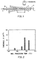
- Double cantilever beam specimens consisting of a thin layer of fluorochemical inorganic oxide beams, as shown schematically in Figure 1, were prepared using the following lamination procedure.
- the beams that were used were clean, highly-polished, inorganic oxide plates (1).
- the plates were coated prior to lamination with an adhesion promoting agent - sucrose octaacetate, by dip coating the inorganic oxide substrate in a warm 2% solution of sucrose octaacetate in isopropanol.
- the loose sandwich was placed between Kapton®-lined tool steel platens in a hydraulic press and a force of 9 kN (2000 lb.) gradually applied.
- the platens were subsequently heated to a specified maximum temperature, at approximately 500°C/hr, held at that maximum temperature for 10 minutes, and allowed to cool naturally under a power off condition.
- the residual pressure was released and the Kapton® films stripped off the platens and the inorganic oxide beams. Excess fluorochemical film that was forced out of the sandwich during pressing was removed with a sharp blade.
- Double-cantilever-beam (DCB) measurements were carried out in constant displacement mode by driving a steel blade (3) of known dimensions into the region without the fluorochemical film.
- the sandwich and blade arrangement were set up on a universal servo-hydraulic testing machine (Model 8100, MTS Systems Corp, Eden Prairie, Minnesota) and the delamitiation between the inorganic beams and the fluorochemical observed in transmitted light using a long (40 cm) working distance microscope with an encoded vertical-travel stage, accurate to 10 microns (Questar QM 100, Questar Corp, New Hope, Pennsylvania).
- the testing procedure consists of driving the steel blade into the interface and observing the subsequent delamination motion with the microscope.
- Figure 2 plots the measured threshold adhesion level, G , as a function of maximum lamination temperature for the Teflon® PFA 350/sucrose acetate/Pyrex® system.
- Figure 3 plots the measured threshold adhesion level, G , as a function of maximum lamination temperature for the Tefzel® 280/sucrose acetate/Pyrex® system. Again the adhesion levels are strongly dependent on lamination temperatures, passing through a maximum.
- the Tefzel® 280 containing laminate demonstrates higher adhesion levels than the Teflon® PFA 350 containing laminate and that peak adhesion is obtained at a lower processing temperature.
- Sucrose octaacetate (2 parts) was dissolved in warm isopropanol (98 parts). Pyrex® plates, 25.4 mm x 76.2 mm x 0.762 mm (1S x 3S x 0.030S), that had been polished on their largest faces, and degreased in isopropanol, were dipped into the warm sucrose octaacetate solution, leaving approximately one centimeter of the bar protruding above the surface of the solution for the purpose of gripping. The bars were withdrawn from the solution at a rate of roughly 15 centimeters per second, to yield a thin layer of solution adhering to the bar.
- the coated bar was allowed to dry under ambient conditions, leaving a white translucent layer of sucrose octaacetate on the surfaces of the bars.
- On top of the Teflon® PFA 350 film was placed a second coated Pyrex® bar. The loose sandwich was placed between the Kapton®-lined tool steel platens of a hydraulic press and a force of 9 kN (2000 lb.) gradually applied.
- Example 1 These examples are identical to Example 1 with the exception that the maximum heating temperatures during pressing was varied. The conditions and results are shown in Table 1.
- Example 1 These examples are identical to Example 1, with the exception that the fluorocopolymer used between the two Pyrex® plates was Tefzel® 280 with a thickness of 100 microns before pressing.
- the processing conditions and results are shown in Table 1.
- Example 2 This sample is identical to Example 1 with the exceptions that the Pyrex® bars were not coated with an adhesion promoting material prior to the lamination process, and the peak temperature during pressing was 350 degrees centigrade. Additional samples prepared in this method were immersed in boiling water and were shown to delaminate in less than 1 hour.
- Example 5 This sample is identical to Example 5 with the exceptions that the Pyrex® bars were not coated with an adhesion promoting material prior to the lamination process, and the peak temperature during pressing was 295 degrees centigrade. Processing conditions and results for Examples 1 through 7 and Comparative Examples 8 and 9 Example Number Maximum Temperature (°C) Energy Release Rate (J/m 2 ) 1 315 9 2 335 16 3 345 62 4 355 48 5 295 42 6 320 188 7 332 155 8 350 15 9 295 15
- Teflon® PFA 350 was melted in a 70 cubic centimeter Haake mixer equipped with roller blades at 350°C while running at 15 RPM.
- 35 parts aluminum oxide Showa AL-45H
- the speed of the mixer was increased to 100 RPM, where it was held constant for 30 minutes.
- the temperature of the mixture was maintained at 350°C by air cooling the mixer. After mixing, the cover of the mixer was removed, and the compounded polymer was cut out of the apparatus using copper/beryllium alloy knives.
- the irregularly shaped chunks were placed between steel plates lined with Kapton® film, and pressed to a thickness of roughly 2.5 mm (0.1 inches) using a Carver Press with heated platens that had been preheated to 350°C.
- Kapton® is a thermally stable polyimide film obtainable from the DuPont Company, Wilmington, Delaware.
- the steel/Kapton®/compounded PFA assembly was then moved to a water cooled press and cooled to room temperature while under pressure. The thick sheet was cut into smaller pieces, half of which were reloaded between Kapton® lined steel plates and reheated in the Carver press. The material was pressed to a thickness of roughly 1 mm (0.04 inches).
- Example 10 was identical to Example 14 with the exception that the mixed aluminum oxide/sucrose octaacetate powders were calcined under nitrogen at 375°C for one hour and allowed to cool to room temperature under nitrogen prior to mixing the powders with the Teflon® PFA 350.
- Mechanical Properties of Examples 10 to 15 EXAMPLE NO. MAXIMUM STRESS (MPa/PSI) STRAIN AT FAILURE (%) 10 15.38/2231 211 11 18.31/2656 268 12 19.30/2799 102 13 22.27/3230 123 14 22.50/3263 159 15 19.93/2891 155
- sucrose octaacetate is used as the material to promote adhesion between the filler particles and the fluoropolymer matrix. Where present, the amount of sucrose octaacetate is indexed to the amount of aluminum oxide at 1 part of sucrose octaacetate to 10 parts aluminum oxide. The thermal conductivity is compiled in W/m/0K, while the failure strain is listed in percent and the yield stress is compiled in megapascals (pounds per square inch). All of these samples were mixed as in Example 14 above. In Table 3, all composites except Example 21 use Showa's AL-45H aluminum oxide powder as the filler.
- Example 21 uses Showa's AS-10 aluminum oxide powder as the filler Examples 16, 22, 24 and 25 were fabricated without sucrose octaacetate as comparative examples, while Samples 23 and 24 use PFA 450 as the fluoropolymer matrix and Examples 26 and 27 use FEP 140 as the fluoropolymer matrix. EX.
Landscapes
- Chemical & Material Sciences (AREA)
- Engineering & Computer Science (AREA)
- Ceramic Engineering (AREA)
- Organic Chemistry (AREA)
- Materials Engineering (AREA)
- Structural Engineering (AREA)
- Chemical Kinetics & Catalysis (AREA)
- Polymers & Plastics (AREA)
- Health & Medical Sciences (AREA)
- Medicinal Chemistry (AREA)
- Life Sciences & Earth Sciences (AREA)
- General Chemical & Material Sciences (AREA)
- Geochemistry & Mineralogy (AREA)
- Manufacturing & Machinery (AREA)
- Inorganic Chemistry (AREA)
- Compositions Of Macromolecular Compounds (AREA)
- Laminated Bodies (AREA)
- Adhesives Or Adhesive Processes (AREA)
- Manufacture Of Macromolecular Shaped Articles (AREA)
Description
- This invention concerns a process for the improvement of adhesion between fluoropolymers or fluorocopolymers and inorganic compounds and to composite materials made by this process.
- Various approaches have been used in the past in attempts to increase the adhesion between fluoropolymers and substrates or filler materials.
- U.S. Patent No. 3,787,281, Effenberger, discloses a process for bonding polytetrafluoroethylene to glass, fibers or plates, using a hydrolyzable silane or a methacrylato chromic chloride as bonding agent.
- Canadian Patent No. 764,537 Bowman, discloses adhesive compositions suitable for use with fluorocarbon polymers comprising reactive (hydrolyzable) silanes or siloxanes. The fluorocarbon polymer is optionally pretreated with a solution of sodium in ammonia or a solution of sodium naphthalene in tetrahydrofuran.
- U.S. Patent No. 3,804,802, Bergna, discloses composites of thermoplastic resins, including polyfluoroolefins, with glass fiber materials utilizing a nitrate-containing coupling agent to increase adhesion between the components.
- U.S. Patents No. 4,902,444 and 5,000,875 disclose melt processable fluorinated tetrafluoroethylene copolymer and terpolymer compositions that are treated with a fluorinating agent to remove unstable end groups, then compounded with electrically conductive agents or thermally conductive fillers.
- U.S. Patent No. 5,024,871, Arthur, discloses a ceramic-filled fluoropolymeric composite wherein the filler, preferably fused amorphous silica, is coated with a zirconate or titanate coating. Said composite possesses excellent thermal, mechanical and electrical properties. U.S. Patents No. 5,061,548 and 5,384181, Arthur, disclose similar composites wherein the surface coating agent is a silane.
- This invention provides a process for the improvement of adhesion between fluoropolymers or fluorocopolymers and inorganic compounds comprising the steps of 1) contacting the inorganic compound with an adhesion promoter to form a coated inorganic compound, 2) contacting the coated inorganic compound with the fluoropolymer or fluorocopolymer, and 3) heating the coated inorganic compound-contacted, fluoropolymer or fluorocopolymer to a temperature sufficient to convert the adhesion promoter to a carbon-rich char.
- This invention also includes composite materials made by the process. These composites of an inorganic compound and a fluoropolymer or fluorocopolymer have an interfacial layer of carbon-rich char which improves the adhesion of the inorganic compound to the fluoropolymer or fluorocopolymer.
-
- Figure 1 is a schematic drawing of a sandwich specimen and the double cantilevered beam (DCB) experimental setup.
- Figure 2 shows adhesion level (G) as a function of lamination temperature for Teflon® PFA 350 on Pyrex® glass.
- Figure 3 shows adhesion level (G) as a function of lamination temperature for Tefzel® 280 on Pyrex® glass.
-
- The process of the present invention concerns a process for the improvement of adhesion between fluorohomopolymers or fluorocopolymers and inorganic compounds.
- Fluorohomopolymers or fluorocopolymers, hereinafter generally referred to as fluorochemicals, usable in the process of the present invention include poly(tetrafluoroethylene), PTFE (Teflon®); tetrafluoroethylene-hexafluoropropylene copolymer, also referred to as fluorinated ethylene-propylene copolymer, FEP (Teflon® FEP); ethylene-tetrafluoroethylene copolymer, ETFE (Tefzel®); perfluoroalkoxy modified tetrafluoroethylenes, PFA, e.g., tetrafluoroethylene-perfluoropropylvinylether copolymer (Teflon® PFA); poly(chlorotrifluorotetrafluoroethylene), PCTFE; vinylidene fluoride-tetrafluoroethylene copolymer, VF2-TFE; poly(vinylidene fluoride), (Kynar®); and tetrafluoroethylene-perfluorodioxole copolymers, (Teflon AF®). Included in the group of fluoroelastomers which are fluorohomopolymers or fluorocopolymers are vinylidene fluoride-hexafluoropropylene copolymer (Viton® A); vinylidene fluoride-hexafluoropropylene-tetrafluoroethylene terpolymer, (Viton® B); and tetrafluoroethylene-perfluoro(methylvinylether) plus cure site monomer terpolymer (Kalrez®).
- Of the foregoing fluorochemicals, preferred are tetrafluoroethylene-hexafluoropropylene copolymer, ethylene-tetrafluoroethylene copolymer, perfluoroalkoxy modified tetrafluoroethylenes and tetrafluoroethylene-perfluorodioxole copolymers.
- Inorganic compounds usable in the process of the present invention include but are not limited to alumina, silica, titania, zirconia, silicate glass, aluminum nitride, silicon carbide and boron carbide. The inorganic compound may exist in various physical forms, i.e., in the form of a powder, a solid shape having a surface, possibly a very smooth surface, or in the shape of a surface coating on a secondary substrate. This secondary substrate could, for example, be a metal. One specific example of the inorganic compound being a surface coating on a secondary substrate would be alumina on an aluminum metal secondary substrate.
- Adhesion promoters usable in the process of the present invention are organic compounds that convert to carbon-rich chars at elevated temperatures in non-oxidizing environments. Suitable compounds include but are not limited to sucrose, sucrose octaacetate (SOA), abietic acid, poly(acrylic acid) and pitch.
- Contacting the inorganic compound with the adhesion promoter may be accomplished by various methods depending on the state of the inorganic compound and the adhesion promoter. If, for example, the inorganic compound comprises a solid surface, either as a monolithic structure or as a surface coating on a secondary substrate, the inorganic compound's surface may be coated with a solution of the adhesion promoter in a compatible solvent. Other methods of coating including but not limited to deposition from a vapor phase, evaporation, sputtering, or even dusting the surface with powder are acceptable. If the inorganic compound is in the form of a powder and the adhesion promoter is a powder, powder mixers, such as a Tekmar powder mill may be employed. If the adhesion promoter is a liquid, the adhesion promoter may be added to the inorganic compound, then mixed in, for example, a Spex mill. Either solid or liquid adhesion promoters may be dissolved in a compatible solvent and coated on a surface, as described above, or added to the inorganic compound powder in that form.
- Optionally the adhesion-promoter contacted inorganic compound may be dried, if solvent wet, prior to contacting it further with fluorochemical.
- Contacting the adhesion-promoted inorganic compound with a melt processable fluorochemical is accomplished in various means depending on the physical form of both materials. If the adhesion-promoted inorganic compound is in the form of a powder, this is accomplished most easily by adding the solid to the fluorochemical in its molten state and using, for example, a Haake® melt compounder to assure uniformity. It is also possible to mix solid polymer with solid adhesion-promoted inorganic compound and heating the mixture prior to melting, accompanied by or prior to melting, followed by mixing. In either of the above two embodiments, this contacting step and the subsequent heating to elevated temperatures may be conducted essentially simultaneously.
- If the adhesion-promoted inorganic compound comprises a solid surface, either as a monolithic structure or as a surface coating on a secondary substrate, the adhesion-promoted inorganic compound surface may be laminated with a film of solid fluorochemical, coated with a suspension of fluorochemical in an appropriate medium, or coated with a solution of the fluorochemical in a compatible solvent.
- Heating the adhesion-promoted, inorganic compound-contacted fluorochemical to elevated temperatures to bring about the adhesive bond can be carried out in a melt state as described above for powdered form adhesion-promoted inorganic compound or between heated rolls, in sintering ovens or in a heated press for laminar structures.
- The temperature utilized for bringing about the adhesive bond depends on the nature of the adhesion promoter, the nature of the fluoropolymer of fluorocopolymer and the nature of the inorganic compound. The temperature must be sufficient to convert the adhesion promoter to a carbon-rich char and below the temperature needed to thermally damage the other materials present. Temperatures above 250°C are usually employed. Typically temperatures from 250°C to about 375°C are employed.
- Optionally, pressure may be applied during the heating stage. This is most easily envisioned when the adhesion-promoted inorganic compound and fluorochemical are in laminar structure. If this general method is used, it is also optional to place pellets of the fluorochemical on the surface of the adhesion promoted inorganic compound, and rely upon the applied pressure to spread the fluorochemical onto the adhesion promoted surface.
- The utility of the products of the process of the present invention depend on the physical form of the fluorochemical-adhesion-promoted inorganic compound construct. If the adhesion-promoted inorganic compound is in the form of a powder and this powder is dispersed in a fluorochemical matrix, depending on the nature of the inorganic compound, various advantageous properties may be developed in the fluorochemical-inorganic compound composite. For example, thermal or electrical conductivity of said composite may be attractive. If the fluorochemical-inorganic compound construct comprises an inorganic oxide surface-coated with a fluorochemical, the surface properties of said inorganic oxide may be advantageously modified with respect to, for example, durability, non-stick performance, corrosion resistance, or wetting characteristics.
- Thermally conductive fluorochemicals are useful in heat exchanger tubes for use at elevated temperatures in corrosive environments and fuser rolls in copier machines. For maximum utility, the material should be processable by extrusion, and the properties of the material in use must include at least modest yield strength, failure strain and toughness.
- In some cases, the filler material is selected to provide a high degree of thermal conductivity. The most preferred inorganic filler material is aluminum oxide powder, selected for its moderate thermal conductivity and excellent chemical resistance. In order to increase the thermal conductivity of the composite by a factor greater than 2, it is necessary to include greater than 20 volume percent of the highly thermally conductive phase into the fluorochemical. However, composites containing greater than 60 volume percent filler are generally unacceptable due to incomplete filling of the interparticle space with matrix material. Even 20% by volume of filler has the potential of causing a problem in that the mechanical properties, such as ultimate strength and strain to failure, are degraded substantially without large increases in yield stress. This results in a decrease in toughness of the composite and decreases the utility of the material. The most accepted reason for the degradation of the mechanical properties with increased filler loading is that there is very little adhesion between the fluorochemical matrix and the filler phase. Therefore, at a certain strain, the interface fails, causing the formation of voids at the matrix/filler interface and subsequent yield and failure of the matrix. This invention relies on the creation of strong filler/matrix bonding so that the potential problem of composites with low yield stress is avoided.
- The problem of sub-standard mechanical properties in filled fluorochemicals, for example in
Teflon® PFA 350, has been examined previously.Teflon® PFA 350 is a tetrafluoroethylene-perfluoropropylvinylether copolymer obtained from the DuPont Company, Wilmington, Delaware.Unfilled PFA 350 has a yield stress of 15.16 MPa (2200 psi), an ultimate strength of 27.58 MPa (4000 psi) and a strain to failure of 330%. At low loadings of aluminum oxide in PFA, the ultimate stress an the failure strain remain quite high, but decrease as the aluminum oxide loading increases. At 5 and 10 percent by weight aluminum oxide, the ultimate stresses were 27.23 MPa (3950 psi) and 26.20 MPa (3800 psi), the yield stresses were 15.03 MPa (2180 psi) and 14.31 MPa (2075 psi), and the failure strains were 315% and 320% respectively. However, the thermal conductivity of these samples is only marginally improved over the unfilled matrix material. For more substantial improvements in thermal conductivity, upwards of 35% by weight aluminum oxide must be included in the fluorochemical matrix. - The mechanical properties of
Teflon® PFA 350/aluminum oxide composites, especially where the filler loading is greater than 35% by weight but less than about 75% by weight, are improved by coating or mixing the aluminum oxide filler with a surface treating agent and subsequently combining the treated powder with the fluorochemical at an elevated temperature. The improved properties are believed to result from improved bonding of the filler powder to the fluoropolymer matrix relative to similar materials that contain uncoated aluminum oxide. This improved bonding results from the presence of an interfacial layer of carbon or carbon-rich char between the oxide and the fluoropolymer. - The most preferred filler used in the process of the present invention is aluminum oxide, however, other inorganic powders with suitable thermal conductivities may be substituted. Preferred thermally conductive fillers are defined as those with thermal conductivities greater than 10 watts per meter degree Kelvin. Preferred thermally conductive fillers are characterized by their having a small maximum primary particle size combined with a low level of agglomeration. Some grades of aluminum oxide usable in the process of the present invention include Showa AL-45H (most preferred), Showa AS-40, Showa AS-10, Alcoa A-16 and General Abrasives Type 55. Aluminum.oxide of the grades indicated can be purchased from Showa Denko America, New York, New York and General Abrasives Co., Niagara Falls, New York.
- A wide variety of particle sizes can be used for the filler material. For use in melt compounding, the preferred size range will have a mean particle size below 30 microns and a maximum less than 50 microns, with less than 10% of the material smaller than 0.1 microns. The most preferred distribution will have a mean less than 10 microns and a maximum less than 15 microns with less than 10% of the material smaller than 0.1 microns. Filler powders substantially greater in size than those in this range result in composites that fail at very low strains, while composites made from fillers that are substantially smaller than the preferred range result in materials that are difficult to process due to their high viscosity during melt compounding. If processing routes other than melt compounding are used, powders with average particle sizes less than 1 micron, with a substantial fraction below 0.1 micron become more suitable.
- Particle size distribution are conveniently determined with a Horiba LA-500 Laser Diffraction Particle Size Distribution Analyzer, available from Horiba Instruments Incorporated, Irvine, CA. Samples are prepared by adding 0.5 g of powder to a 50 ml pyrex beaker. To this is added 20 ml of isopropanol. This mixture is sonicated until homogeneous in a Heat Systems Ultrasonics W-375 Sonicator/Cell Disruptor equipped with a 0.5 inch (1-25 cm) diameter ultrasonic horn. The Horiba small sample diffraction cell is filled to two thirds of its capacity with isopropyl alcohol, and the sonicated concentrate is added dropwise to the diffraction cell until the dilution is considered favorable as determined by the Horiba LA-500 instrument.
- There are two important features of the surface treated filler particles that are adjusted so that the surface treated filler material can function in the process of the present invention. Small unagglomerated particles are preferred in order to facilitate large strains-to-failure. Carbon coating of the filler particles causes adhesion between the particles and the fluorochemical matrix-and therefore produces reinforcement of the matrix. Both of these features are essential to the formation of composites with optimal mechanical properties. Small, unagglomerated particles that do not adhere to the matrix provide sites for nucleation of porosity at the particles surfaces, called cavitation, which leads to low yield stresses and necking of the composites. Large or agglomerated particles that have good adhesion to the matrix cause reinforcement at very small strains, however, they fail at low strains relative to those desired. Having both features present, small unagglomerated particles and good particle/matrix adhesion, enables the fabrication of composites with the desired yield stress, ultimate stress and failure strain.
- In the case of composites of this invention which are laminated structures, improvement was measured in the adhesion of fluorochemicals to inorganic compounds using a double-cantilever-beam (DCB) geometry. This method was employed, in constant displacement mode, with appropriate sandwich specimens produced by laminating a specified fluorochemical film between inorganic oxide beams at elevated temperature and pressure. The DCB method, when used with transparent beams, has the advantage of allowing in situ observation of crack growth in a highly stabilizing crack-driving field. Adhesion is quantified in this geometry from the elastic energy released, G, in the inorganic oxide beams on extension of the delamination at the interface between the inorganic oxide beam and the fluoropolymer or fluorocopolymer film. Adhesion in these systems depends strongly on lamination temperature, passing through a maximum.
- Double cantilever beam specimens consisting of a thin layer of fluorochemical inorganic oxide beams, as shown schematically in Figure 1, were prepared using the following lamination procedure. The beams that were used were clean, highly-polished, inorganic oxide plates (1). The plates were coated prior to lamination with an adhesion promoting agent - sucrose octaacetate, by dip coating the inorganic oxide substrate in a warm 2% solution of sucrose octaacetate in isopropanol. A piece of fluorochemical film (2), 25 microns (0.001S) thick, was carefully placed between two previously coated beams. The film was positioned to leave a section of the sandwich without film in order to generate a starter crack for mechanical testing. The loose sandwich was placed between Kapton®-lined tool steel platens in a hydraulic press and a force of 9 kN (2000 lb.) gradually applied. The platens were subsequently heated to a specified maximum temperature, at approximately 500°C/hr, held at that maximum temperature for 10 minutes, and allowed to cool naturally under a power off condition. The residual pressure was released and the Kapton® films stripped off the platens and the inorganic oxide beams. Excess fluorochemical film that was forced out of the sandwich during pressing was removed with a sharp blade.
- Double-cantilever-beam (DCB) measurements were carried out in constant displacement mode by driving a steel blade (3) of known dimensions into the region without the fluorochemical film. The sandwich and blade arrangement were set up on a universal servo-hydraulic testing machine (Model 8100, MTS Systems Corp, Eden Prairie, Minnesota) and the delamitiation between the inorganic beams and the fluorochemical observed in transmitted light using a long (40 cm) working distance microscope with an encoded vertical-travel stage, accurate to 10 microns (
Questar QM 100, Questar Corp, New Hope, Pennsylvania). The testing procedure consists of driving the steel blade into the interface and observing the subsequent delamination motion with the microscope. Because many inorganic oxides and thin fluoropolymer and fluorocopolymer films are transparent, the resulting crack could be imaged in transmitted light. The crack tip is clearly delineated by Fizeau interference fringes as crack opening displacements close to the tip approach dimensions of the wavelength of light. Delamination size measurements were made as a function of time, and the threshold crack length identified as the condition when no crack extension was observed over a 24 hr period. - Adhesion, in terms of the energy release rate, G, was determined for a constant wedging displacement, by noting that the energy required to separate the interface on unit crack extension is equal to the elastic strain energy released in the two cantilever beams as they unload on crack propagation:
d - Figure 2 plots the measured threshold adhesion level, G, as a function of maximum lamination temperature for the
Teflon® PFA 350/sucrose acetate/Pyrex® system. Several features may be noted from these data. First, the adhesion level is strongly dependent on lamination temperature, starting at some 10 J.m-2 at 315°C and increasing to a maximum of some 60 J.m-2 at around 345°C. Second, the adhesion appears to peak before decreasing at still higher temperatures. Excessive temperatures at which polymer degradation occurs may determine the upper lamination temperatures and lead to a peak in the adhesion energy. - Figure 3 plots the measured threshold adhesion level, G, as a function of maximum lamination temperature for the Tefzel® 280/sucrose acetate/Pyrex® system. Again the adhesion levels are strongly dependent on lamination temperatures, passing through a maximum.
- The Tefzel® 280 containing laminate demonstrates higher adhesion levels than the
Teflon® PFA 350 containing laminate and that peak adhesion is obtained at a lower processing temperature. - Sucrose octaacetate (2 parts) was dissolved in warm isopropanol (98 parts). Pyrex® plates, 25.4 mm x 76.2 mm x 0.762 mm (1S x 3S x 0.030S), that had been polished on their largest faces, and degreased in isopropanol, were dipped into the warm sucrose octaacetate solution, leaving approximately one centimeter of the bar protruding above the surface of the solution for the purpose of gripping. The bars were withdrawn from the solution at a rate of roughly 15 centimeters per second, to yield a thin layer of solution adhering to the bar. The coated bar was allowed to dry under ambient conditions, leaving a white translucent layer of sucrose octaacetate on the surfaces of the bars. A film of
Teflon® PFA Teflon® PFA 350 film was placed a second coated Pyrex® bar. The loose sandwich was placed between the Kapton®-lined tool steel platens of a hydraulic press and a force of 9 kN (2000 lb.) gradually applied. The platens were subsequently heated to 315 degrees centigrade, at approximately 500°C/hr, held at that maximum temperature for 10 minutes, and allowed to cool naturally under a power off condition (overnight). The residual pressure was released and the Kapton® was mechanically stripped from the surfaces of the beams. The resulting double cantilever beams were tested as previously described. Adhesion results are shown in Table 1. Additional samples prepared in this method were immersed in boiling water and were shown to resist delamination for more than 24 hours. - These examples are identical to Example 1 with the exception that the maximum heating temperatures during pressing was varied. The conditions and results are shown in Table 1.
- These examples are identical to Example 1, with the exception that the fluorocopolymer used between the two Pyrex® plates was Tefzel® 280 with a thickness of 100 microns before pressing. The processing conditions and results are shown in Table 1.
- This sample is identical to Example 1 with the exceptions that the Pyrex® bars were not coated with an adhesion promoting material prior to the lamination process, and the peak temperature during pressing was 350 degrees centigrade. Additional samples prepared in this method were immersed in boiling water and were shown to delaminate in less than 1 hour.
- This sample is identical to Example 5 with the exceptions that the Pyrex® bars were not coated with an adhesion promoting material prior to the lamination process, and the peak temperature during pressing was 295 degrees centigrade.
Processing conditions and results for Examples 1 through 7 and Comparative Examples 8 and 9 Example Number Maximum Temperature (°C) Energy Release Rate (J/m2) 1 315 9 2 335 16 3 345 62 4 355 48 5 295 42 6 320 188 7 332 155 8 350 15 9 295 15 - 65 parts
Teflon® PFA 350 was melted in a 70 cubic centimeter Haake mixer equipped with roller blades at 350°C while running at 15 RPM. When the polymer was molten, 35 parts aluminum oxide (Showa AL-45H) was slowly added to the polymer. After the addition of the inorganic powder, the speed of the mixer was increased to 100 RPM, where it was held constant for 30 minutes. The temperature of the mixture was maintained at 350°C by air cooling the mixer. After mixing, the cover of the mixer was removed, and the compounded polymer was cut out of the apparatus using copper/beryllium alloy knives. The irregularly shaped chunks were placed between steel plates lined with Kapton® film, and pressed to a thickness of roughly 2.5 mm (0.1 inches) using a Carver Press with heated platens that had been preheated to 350°C. Kapton® is a thermally stable polyimide film obtainable from the DuPont Company, Wilmington, Delaware. The steel/Kapton®/compounded PFA assembly was then moved to a water cooled press and cooled to room temperature while under pressure. The thick sheet was cut into smaller pieces, half of which were reloaded between Kapton® lined steel plates and reheated in the Carver press. The material was pressed to a thickness of roughly 1 mm (0.04 inches). The steel/Kapton®/compounded PFA assembly was then cooled as before in a water cooled press. Tensile bars (ASTM D1708) were cut from the sheets and tested in an Instron load frame that was equipped with a 91 kg (200 pound) load cell at 0.21 mm/sec (0.5 inches per minute). The results are reported in Table 2. Some of this material was observed while under strain in an optical microscope at a magnification of 200X. Suitable Leitz microscopes are available from Leica, Inc., Malvern, Pennsylvania. Cavitation at the matrix/filler interface was visible at strains less than 50%, and persisted until failure of the material. - 35 parts aluminum oxide (General Abrasives Type 55) was calcined at 800°C in air for two hours, and allowed to cool to room temperature. The previously heated powder was then added to the polymer in place of the Showa AL-45H and processed as in Comparative Example 10.
- 50 parts aluminum oxide (Showa AL-45H) was loaded into a Tekmar Powder Mill. One part of poly(acrylic acid) powder, molecular weight 5000 was poured over the top of the aluminum oxide. Poly(acrylic acid) can be obtained from Aldrich Chemical Company, Milwaukee, Wisconsin. The cover was installed on the mill and the mill started. The resulting powder mixture appeared to be uniform in color. 35 parts of this powder mixture was added to molten
Teflon® PFA 350 as in Example 10, substituted for the Showa AL-45H aluminum oxide. - 50 parts aluminum oxide (Showa AL-45H) was loaded into a Spex Vibratory Mill. One part of abietic acid powder was poured over the top of the aluminum oxide powder. Abietic acid is obtainable from the Fluka Chemical Company, New York, New York. The cover was installed on the mill and the mill started. The resulting powder mixture appeared to be uniform in color. 35 parts of this powder mixture was added to molten
Teflon® PFA 350 as in Example 10, substituted for the Showa AL-45H aluminum oxide. - 50 parts aluminum oxide (Showa AL-45H) was loaded into a Spex Vibratory Mill. One part of sucrose octaacetate powder was poured over the top of the aluminum oxide powder. Sucrose octaacetate can be obtained from Aldrich Chemical Company, Milwaukee, Wisconsin. The cover was installed on the mill and the mill started. The resulting powder appeared to be uniform in color. 35 parts of this powder mixture was added to molten Teflon® PFA as in Example 10, substituted for the Showa AL-45H aluminum oxide. Some of this material were observed while under strain in an optical microscope at a magnification of 200X. Cavitation at the matrix/filler interface was not observed up until and including the failure of the material.
- This example was identical to Example 14 with the exception that the mixed aluminum oxide/sucrose octaacetate powders were calcined under nitrogen at 375°C for one hour and allowed to cool to room temperature under nitrogen prior to mixing the powders with the
Teflon® PFA 350.Mechanical Properties of Examples 10 to 15 EXAMPLE NO. MAXIMUM STRESS (MPa/PSI) STRAIN AT FAILURE (%) 10 15.38/2231 211 11 18.31/2656 268 12 19.30/2799 102 13 22.27/3230 123 14 22.50/3263 159 15 19.93/2891 155 - In Examples 16 through 26, all compositions are described in parts by weight. Unless otherwise indicated in Table 3, sucrose octaacetate is used as the material to promote adhesion between the filler particles and the fluoropolymer matrix. Where present, the amount of sucrose octaacetate is indexed to the amount of aluminum oxide at 1 part of sucrose octaacetate to 10 parts aluminum oxide. The thermal conductivity is compiled in W/m/0K, while the failure strain is listed in percent and the yield stress is compiled in megapascals (pounds per square inch). All of these samples were mixed as in Example 14 above. In Table 3, all composites except Example 21 use Showa's AL-45H aluminum oxide powder as the filler. Example 21 uses Showa's AS-10 aluminum oxide powder as the filler Examples 16, 22, 24 and 25 were fabricated without sucrose octaacetate as comparative examples, while Samples 23 and 24 use PFA 450 as the fluoropolymer matrix and Examples 26 and 27 use FEP 140 as the fluoropolymer matrix.
EX. # Parts Fluoropolymer Parts Alumina Failure Strain Failure Stress (MPa/psi) Thermal Conductivity 16 100 0 337 25.70/3728 0.22 17 65 35 124 22.40/3249 0.44 18 55 45 97 26.55/3851 0.68 19 45 55 58 25.86/3751 0.92 20 35 65 36 25.85/3749 1.14 21 35 65 1.36 22 65 35 256 15.62/2251 23 65 35 148 24.99/3625 24 65 35 254 18.73/2716 25 65 35 62 17.40/2523 26 65 35 120 21.05/3053
Claims (14)
- A process for improving adhesion between an inorganic compound and a fluorochemical selected from the group consisting of fluorohomopolymers and fluorocopolymers comprising contacting the inorganic compound with an adhesion promoter to form a coated inorganic compound, contacting the coated inorganic compound with the fluorochemical to form a fluorochemical-coated inorganic compound and heating to a temperature sufficient to convert the adhesion promoter to a carbon-rich char.
- The process of Claim 1 wherein the adhesion promoter is a member selected from the group consisting of sucrose, sucrose octaacetate, abietic acid, poly(acrylic acid), and pitch.
- The process of Claim 1 or Claim 2 wherein the inorganic compound is a member selected from the group consisting of alumina, silica, titania, zirconia, silicate glass, aluminum nitride, silicon carbide and boron carbide.
- The process of any preceding claim wherein the fluorochemical is a member selected from the group consisting of poly(tetrafluoroethylene), tetrafluoroethylene-hexafluoropropylene copolymer, ethylene-tetrafluoroethylene copolymer, perfluoroalkoxy modified tetrafluoroethylenes, poly(chlorotrifluorotetrafluoroethylene), vinylidene fluoride- tetrafluoroethylene copolymer, poly(chlorotrifluorotetrafluoroethylene), vinylidene fluoride-tetrafluoroethylene copolymer, poly(vinylidene fluoride), tetrafluoroethylene-perfluorodioxole copolymers, vinylidene fluoride-hexafluoropropylene copolymer, vinylidene fluoride-hexafluoropropylene-tetrafluoroethylene terpolymer, and tetrafluoroethylene-perfluoro(methylvinylether) plus cure site monomer terpolymer.
- The process of Claim 4 wherein the fluorochemical is a member selected from the group consisting of ethylene-tetrafluoroethylene copolymer, tetrafluoroethylene-hexafluoropropylene copolymer, perfluoroalkoxy modified tetrafluoroethylenes, and tetrafluoroethylene-perfluorodioxole copolymers.
- The process of any preceding claim wherein the combination is heated to a temperature of from 250°C to 375°C.
- The process of Claim 3 wherein the inorganic compound is alumina.
- A composite of an inorganic compound selected from the group consisting of alumina, silica, titania, zirconia, silicate glass, aluminum nitride, silicon carbide and boron carbide and a fluorochemical selected from the group consisting of fluorohomopolymers and fluorocopolymers wherein the inorganic compound is bonded to the fluorochemical by an interfacial layer of carbon-rich char.
- The composite of Claim 8 wherein the fluorochemical is a member selected from the group consisting of poly(tetrafluoroethylene), tetrafluoroethylene-hexafluoropropylene copolymer, ethylene-tetrafluoroethylene copolymer, perfluoroalkoxy modified tetrafluoroethylenes, poly(chlorotrifluorotetrafluoroethylene), vinylidene fluoride-tetrafluoroethylene copolymer, poly(vinylidene fluoride), tetrafluoroethylene-perfluorodioxole copolymers, vinylidene fluoride-hexafluoropropylene copolymer, vinylidene fluoride-hexafluoropropylene-tetrafluoroethylene terpolymer, and tetrafluoroethylene-perfluoro(methylvinylether) plus cure site monomer terpolymer.
- The composite of Claim 9 wherein the fluorochemical is a member selected from the group consisting of ethylene- tetrafluoroethylene copolymer, tetrafluoroethylene-hexafluoropropylene copolymer, perfluoroalkoxy modified tetrafluoroethylenes, and tetrafluoroethylene-perfluorodioxole copolymers.
- The composite of Claim 8 wherein the inorganic compound is alumina.
- The composite of Claim 11 wherein the composite is from 35% by weight to 75% by weight alumina.
- A composite of Claim 8 wherein the inorganic compound is in the form of a solid surface.
- A composite of Claim 8 wherein the inorganic compound is in the form of a powder.
Applications Claiming Priority (3)
| Application Number | Priority Date | Filing Date | Title |
|---|---|---|---|
| US88295P | 1995-07-12 | 1995-07-12 | |
| US882 | 1995-07-12 | ||
| PCT/US1996/011491 WO1997002904A1 (en) | 1995-07-12 | 1996-07-10 | Improved fluoropolymer adhesion |
Publications (2)
| Publication Number | Publication Date |
|---|---|
| EP0837743A1 EP0837743A1 (en) | 1998-04-29 |
| EP0837743B1 true EP0837743B1 (en) | 2005-05-11 |
Family
ID=21693422
Family Applications (1)
| Application Number | Title | Priority Date | Filing Date |
|---|---|---|---|
| EP96926710A Expired - Lifetime EP0837743B1 (en) | 1995-07-12 | 1996-07-10 | Improved fluoropolymer adhesion |
Country Status (5)
| Country | Link |
|---|---|
| US (1) | US5936009A (en) |
| EP (1) | EP0837743B1 (en) |
| JP (1) | JP3687680B2 (en) |
| DE (1) | DE69634725T2 (en) |
| WO (1) | WO1997002904A1 (en) |
Families Citing this family (8)
| Publication number | Priority date | Publication date | Assignee | Title |
|---|---|---|---|---|
| DE29701878U1 (en) * | 1997-02-04 | 1997-07-10 | Hartmuth, Werner, 66955 Pirmasens | Polytetrafluoroethylene (PTFE) glass fabric film |
| US20030203980A1 (en) * | 2002-04-30 | 2003-10-30 | Valdes Reynaldo A. | Sol-gel composition, methods for manufacturing sol-gels, and applications for sol-gels |
| US7488511B2 (en) * | 2002-06-27 | 2009-02-10 | Orion Industries, Ltd. | Method of manufacturing tetrafluorethylene perfluoromethyl vinyl ether copolymer coated glass |
| WO2004103699A2 (en) * | 2003-05-16 | 2004-12-02 | Garlock Sealing Technologies, Inc. | Composite plastic material |
| EP2112496A3 (en) * | 2008-04-23 | 2013-04-10 | Fraunhofer-Gesellschaft zur Förderung der angewandten Forschung e.V. | Method for repeated calculation of the bond strength of substrates bonded to each other |
| DE102009008593A1 (en) * | 2009-02-12 | 2010-08-19 | Robert Bosch Gmbh | Heat exchanger for use in e.g. oil condensing boilers for heat exchange between hot gas and boiler water, has coating consisting of plastic, which is processed in form of powder coating or in fluid phase |
| JP2013023664A (en) * | 2011-07-25 | 2013-02-04 | Sumihiko Kurita | Thermal conductive composition and thermal conductive sheet obtained by treating the same |
| WO2018070838A1 (en) * | 2016-10-14 | 2018-04-19 | 한국기계연구원 | Aluminum powder coated with fluorine-based hydrocarbon polymer layer and preparation method therefor |
Family Cites Families (16)
| Publication number | Priority date | Publication date | Assignee | Title |
|---|---|---|---|---|
| CA764537A (en) * | 1967-08-01 | E.I. Du Pont De Nemours And Company | Fluoroelastomer adhesive compositions | |
| US3787281A (en) * | 1968-10-29 | 1974-01-22 | Du Pont | Forming a hydrolytically stable bond between glass and polytetrafluoroethylene |
| GB1313651A (en) * | 1969-06-25 | 1973-04-18 | Nat Res Dev | Bearing component |
| US3804802A (en) * | 1971-03-01 | 1974-04-16 | Du Pont | Thermoplastic composites with low alkali glass fillers |
| DD155885A1 (en) * | 1980-10-03 | 1982-07-14 | Manfred Rost | SHAVING BLADES WITH CUTTING COATING |
| KR910009491B1 (en) * | 1984-07-09 | 1991-11-19 | Rogers Corp | Flexible circuit lamination |
| JP2504397B2 (en) * | 1985-02-14 | 1996-06-05 | 株式会社東芝 | Hydrogen storage alloy electrode |
| JPS62150527A (en) * | 1985-12-24 | 1987-07-04 | Tdk Corp | Magnetic recording medium |
| DE3635524A1 (en) * | 1986-10-18 | 1988-04-28 | Leybold Ag | METHOD FOR PRODUCING PROTECTIVE LAYERS ON MAGNETIC DATA CARRIERS AND DATA PROCESS PRODUCED BY THE METHOD |
| US5384181B1 (en) * | 1987-02-17 | 2000-06-13 | World Properties Inc | Low volume fraction ceramic filled fluoropolymeric composite material |
| US5024871A (en) * | 1990-02-21 | 1991-06-18 | Rogers Corporation | Ceramic filled fluoropolymetric composite material |
| US5061548A (en) * | 1987-02-17 | 1991-10-29 | Rogers Corporation | Ceramic filled fluoropolymeric composite material |
| US4902444A (en) * | 1988-03-18 | 1990-02-20 | E. I. Dupont De Nemours And Company | Conductive fluoropolymers |
| US5000875A (en) * | 1987-10-16 | 1991-03-19 | E. I. Du Pont De Nemours And Company | Conductive filled fluoropolymers |
| US5055342A (en) * | 1990-02-16 | 1991-10-08 | International Business Machines Corporation | Fluorinated polymeric composition, fabrication thereof and use thereof |
| JPH07243064A (en) * | 1994-01-03 | 1995-09-19 | Xerox Corp | Board cleaning method |
-
1996
- 1996-07-10 JP JP50595997A patent/JP3687680B2/en not_active Expired - Fee Related
- 1996-07-10 DE DE69634725T patent/DE69634725T2/en not_active Expired - Lifetime
- 1996-07-10 WO PCT/US1996/011491 patent/WO1997002904A1/en not_active Ceased
- 1996-07-10 EP EP96926710A patent/EP0837743B1/en not_active Expired - Lifetime
- 1996-07-10 US US08/983,439 patent/US5936009A/en not_active Expired - Lifetime
Also Published As
| Publication number | Publication date |
|---|---|
| WO1997002904A1 (en) | 1997-01-30 |
| EP0837743A1 (en) | 1998-04-29 |
| US5936009A (en) | 1999-08-10 |
| JP3687680B2 (en) | 2005-08-24 |
| DE69634725T2 (en) | 2006-01-19 |
| JPH11509253A (en) | 1999-08-17 |
| DE69634725D1 (en) | 2005-06-16 |
Similar Documents
| Publication | Publication Date | Title |
|---|---|---|
| Mohit et al. | Effect of TiC nanoparticles reinforcement in coir fiber based bio/synthetic epoxy hybrid composites: mechanical and thermal characteristics | |
| US6726994B1 (en) | Structural member of fluorine-containing polymer having adhesive property at high temperature and sliding material produced by using same | |
| US4336175A (en) | Polyimide precursor solutions | |
| Chin et al. | Surface characterization and adhesive bonding of toughened bismaleimide composites | |
| Nasreen et al. | Effect of surface treatment on the performance of composite‐composite and composite‐metal adhesive joints | |
| US5936009A (en) | Fluoropolymer adhesion | |
| US7045044B2 (en) | Dispersion composition containing perfluorocarbon-based copolymer | |
| JP2007508415A (en) | Fluoropolymer composition for powder coating containing aromatic substance | |
| KR20230002304A (en) | Method for preparing dispersions, pastes and powders | |
| Hou et al. | Processing and properties of IM7/LARCTM-RP46 polyimide composites | |
| US5439541A (en) | Method for producing and using crosslinked copolyesters | |
| KR20230036060A (en) | Sizing agents, sized fibers, prepregs and dispersions | |
| US7854882B2 (en) | Moldable and low-temperature cure high-temperature composites | |
| EP1112183B1 (en) | A liquid crystal polymer (in situ) coating for co-cured composite structure | |
| JP7635621B2 (en) | Method for producing modified dispersion and dispersion | |
| CA1333029C (en) | Method for coating a metal substrate by the use of a resin composition | |
| EP4349595B1 (en) | Coating composition and laminate | |
| Ahmed et al. | Investigation on nanoadhesive bonding of plasma modified titanium for aerospace application | |
| Kim et al. | Enhanced interfacial adhesion of carbon fibers to vinyl ester resin using poly (arylene ether phosphine oxide) coatings as adhesion promoters | |
| JP2769319B2 (en) | Complex | |
| Ghosh et al. | Properties of adhesive joint of inorganic nano-filler composite adhesive | |
| Wimolkiatisak et al. | Toughening of graphite–epoxy composites with an electrocopolymerized high‐temperature thermoplastic interphase | |
| JP2024102462A (en) | Fluororesin composition, paint, printed circuit board, dielectric material for circuit board, laminated circuit board, sheet, and method for producing fluororesin composition | |
| Jordan | The processing and mechanical properties of carbon fiber PMR-15 composites | |
| KR20220120546A (en) | dispersion |
Legal Events
| Date | Code | Title | Description |
|---|---|---|---|
| PUAI | Public reference made under article 153(3) epc to a published international application that has entered the european phase |
Free format text: ORIGINAL CODE: 0009012 |
|
| 17P | Request for examination filed |
Effective date: 19971215 |
|
| AK | Designated contracting states |
Kind code of ref document: A1 Designated state(s): DE FR GB IT NL |
|
| 17Q | First examination report despatched |
Effective date: 19980821 |
|
| GRAP | Despatch of communication of intention to grant a patent |
Free format text: ORIGINAL CODE: EPIDOSNIGR1 |
|
| GRAS | Grant fee paid |
Free format text: ORIGINAL CODE: EPIDOSNIGR3 |
|
| GRAA | (expected) grant |
Free format text: ORIGINAL CODE: 0009210 |
|
| AK | Designated contracting states |
Kind code of ref document: B1 Designated state(s): DE FR GB IT NL |
|
| PG25 | Lapsed in a contracting state [announced via postgrant information from national office to epo] |
Ref country code: NL Free format text: LAPSE BECAUSE OF FAILURE TO SUBMIT A TRANSLATION OF THE DESCRIPTION OR TO PAY THE FEE WITHIN THE PRESCRIBED TIME-LIMIT Effective date: 20050511 Ref country code: IT Free format text: LAPSE BECAUSE OF FAILURE TO SUBMIT A TRANSLATION OF THE DESCRIPTION OR TO PAY THE FEE WITHIN THE PRESCRIBED TIME-LIMIT;WARNING: LAPSES OF ITALIAN PATENTS WITH EFFECTIVE DATE BEFORE 2007 MAY HAVE OCCURRED AT ANY TIME BEFORE 2007. THE CORRECT EFFECTIVE DATE MAY BE DIFFERENT FROM THE ONE RECORDED. Effective date: 20050511 |
|
| REG | Reference to a national code |
Ref country code: GB Ref legal event code: FG4D |
|
| REF | Corresponds to: |
Ref document number: 69634725 Country of ref document: DE Date of ref document: 20050616 Kind code of ref document: P |
|
| NLV1 | Nl: lapsed or annulled due to failure to fulfill the requirements of art. 29p and 29m of the patents act | ||
| PLBE | No opposition filed within time limit |
Free format text: ORIGINAL CODE: 0009261 |
|
| STAA | Information on the status of an ep patent application or granted ep patent |
Free format text: STATUS: NO OPPOSITION FILED WITHIN TIME LIMIT |
|
| ET | Fr: translation filed | ||
| 26N | No opposition filed |
Effective date: 20060214 |
|
| PGFP | Annual fee paid to national office [announced via postgrant information from national office to epo] |
Ref country code: DE Payment date: 20130703 Year of fee payment: 18 |
|
| PGFP | Annual fee paid to national office [announced via postgrant information from national office to epo] |
Ref country code: GB Payment date: 20130710 Year of fee payment: 18 Ref country code: FR Payment date: 20130724 Year of fee payment: 18 |
|
| REG | Reference to a national code |
Ref country code: DE Ref legal event code: R119 Ref document number: 69634725 Country of ref document: DE |
|
| GBPC | Gb: european patent ceased through non-payment of renewal fee |
Effective date: 20140710 |
|
| REG | Reference to a national code |
Ref country code: FR Ref legal event code: ST Effective date: 20150331 |
|
| PG25 | Lapsed in a contracting state [announced via postgrant information from national office to epo] |
Ref country code: DE Free format text: LAPSE BECAUSE OF NON-PAYMENT OF DUE FEES Effective date: 20150203 |
|
| REG | Reference to a national code |
Ref country code: DE Ref legal event code: R119 Ref document number: 69634725 Country of ref document: DE Effective date: 20150203 |
|
| PG25 | Lapsed in a contracting state [announced via postgrant information from national office to epo] |
Ref country code: FR Free format text: LAPSE BECAUSE OF NON-PAYMENT OF DUE FEES Effective date: 20140731 Ref country code: GB Free format text: LAPSE BECAUSE OF NON-PAYMENT OF DUE FEES Effective date: 20140710 |