The present invention generally relates to a letterbox
image detection apparatus for detecting a letterbox image
signal.
The present invention relates to a letterbox image
detection apparatus which is utilized in TV receivers having
a wide aspect screen, for detecting boundary position data
of central main images and matte tops or bottoms of screen
images, so as to block out the matte tops and bottoms from
the display screen and thus to expand the main image on the
whole display screen.
In recent years, 16:9 wide aspect TV receivers have been
widely in use to add realism of theater for audiences at home.
Recently, video softwares adapted for broadcast systems
represented by wide-clear visions, VTRs, laser discs, etc.
have been widely used.
EDTV-II type broadcasts are adapted for displaying on 16:9
aspect screens. While some of movies or the like recorded
in laser discs and video tapes have a screen aspect wider than
the 4:3 standard aspect screen as employed in the conventional
TV receivers
These wide aspect programs are transmitted through a TV
broadcast signal so-called letterbox image which is formed
by a central image area (hereinafter referred to main image)
and black belt-shape non-image areas which are disposed on
the top and bottom of the main image. In such wide aspect
TV receivers there are many ones which have functions of
letterbox image detections, i.e., a function of detecting
boundaries of the main images and the non-image areas and then
blocking out the non-image areas from the display screen and
thus expanding the main image both in the vertical and
horizontal directions to display on the full screen of the
TV receivers.
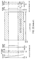
FIGURE 23 is an explanatory diagram showing an image
display for video softwares compatible with conventional wide
aspect TV receivers. Wherein FIGURE 23a shows an image
displayed on the 4:3 aspect screen. While FIGURE 23b shows
the same image displayed on the 16:9 aspect screen.
In FIGURE 23, a video software compatible with a wide
aspect TV receiver provides a black band (hereinafter
referred to the non-image area) on the top and bottom of the
central letterbox image to maintain a compatibility with the
4:3 aspect image from the viewpoint of relationship with the
current 4:3 aspect image signal as shown in FIGURE 23a. Such
picture is called a letterbox image. A wide aspect TV
receiver has a function to detect a letterbox image and expand
the picture in the vertical direction (called as a vertical
expansion) so that the top and bottom non-image areas are not
visible as shown in FIGURE 23b when such a letterbox image
is provided.
FIGURE 24 is an explanatory diagram showing a conventional
image display with a caption band superposed on the lower
non-image area against a video software compatible with wide
aspect TV receivers. Wherein FIGURE 24a shows an image
displayed on the 4:3 aspect screen. While FIGURE 24b shows
an image displayed on the 16:9 aspect screen.
As shown in FIGURE 24a, when an image with a caption band
superposed on the lower non-image area is displayed on the
4:3 aspect screen, the caption band is displayed as it is.
On the other hand, as shown in FIGURE 24b, when an image is
displayed on the 16:9 aspect screen, the vertical expansion
is made likewise but in order to prevent the caption band from
becoming invisible, the image is expanded to the upper
non-image area and the lower portion of the caption band.
To make this operation, most wide aspect TV receivers
includes a letterbox image detector for detecting a letterbox
image signal.
FIGURE 29 is an explanatory diagram showing features of
a letterbox image.
In FIGURE 25, a first feature of the letterbox image is
that there are the non-image areas on the top and bottom of
the letterbox image.
A second feature is that the boundary of the non-image
area and the picture area (hereinafter referred to the main
image) is sharp and expands across one screen image.
A third feature is that there is the main image laterally
expanding around the center of the screen.
When such the first through third features are all
satisfied, the letterbox image detection apparatus
determines that a picture is a letterbox image.
The letterbox image detection apparatus discriminates
between a picture is a letterbox image and a normal aspect
image by obtaining an average luminance level and an average
chrominance level across one screen image for one screen and
by considering an accumulation of that value for one screen.
In general, a large accumulation for several fields or frames
is performed for determining whether a small accumulation
across only one field or frame has stably the feature of the
letterbox image, the determination is made using. In the
example shown in FIGURE 25, an accumulation a0 of an average
luminance level and an average chrominance level satisfies
all the conditions for the letterbox image and are stable over
several pictures, it is determined to be a letterbox image
and a microcomputer in a TV receiver is directed to perform
the vertical expansion. Further, at the same time, when an
accumulation of image signal of the aspect ratio 4:3 having
a picture which is not a letterbox image, that is, having a
picture in the non-image area (hereinafter referred to as a
normal aspect image) is obtained, the letterbox image
detection apparatus regards it as a normal aspect image and
conveys the cancellation of the vertical expansion to the main
microcomputer. If a picture cannot be determined to be a
letterbox image or a normal aspect image, the picture is
regarded as cannot be determined and the microcomputer is
directed to maintain the current state.
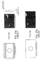
FIGURE 26 shows an example of a letterbox image containing
a caption band.
In FIGURE 26, in case of a picture which has an edge at
the lower side in the accumulation bO of an average luminance
level and an average chrominance level for one screen and
further, the luminance sharply changes in the lower non-image
area, the letterbox image detection apparatus detects it and
conveys that the picture is a letterbox image having a aaption
band to the main microcomputer. At the same time, the picture
start and end position data and the caption band end position
data are conveyed to the main microcomputer.
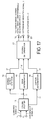
FIGURE 27 is an explanatory diagram showing an example
of a first erroneous detection of a conventional letterbox
image detection apparatus.
In FIGURE 27, a conventional letterbox image detection
apparatus detects a letterbox image using an average
luminance level and an average chrominance level across one
screen image and therefore, when a scene changes, for instance,
from a letterbox image to such a normal aspect image like the
scene of the moon in a dark night as shown in FIGURE 27a, the
average luminance and average chrominance levels detected by
the letterbox image detection apparatus are always below a
threshold of a normal aspect image and the level becomes not
that of a normal aspect image nor a letterbox image. As a
result, the letterbox image detection apparatus outputs a
determining impossible signal. Here, an ordinary vertical
expansion condition when the determining is impossible is to
maintain the current state and therefore, in case of the
display on the 16:9 aspect screen, if an image before the scene
change was fling away by a letterbox image, the display on
the screen remains unchanged and an image chipping occurs in
the true display as shown in FIGURE 27b.
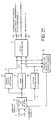
FIGURE 28 is an explanatory diagram showing an example
of a second erroneous detection of a conventional letterbox
image detection apparatus.
In FIGURE 28, an example of an erroneous operation reverse
to the operation in FIGURE 27 is shown. As shown in FIGURE
28a, if a scene was changed from a normal aspect image (on
a normal aspect display) of the scene of the moon in the dark
night to a scene of the sun appearing at the center, the
accumulation cO satisfies all of the features of the letterbox
image at the average luminance and chrominance levels across
one screen image. In this case, the output from the letterbox
image detection apparatus becomes a letterbox image and when
displaying in the 16:9 aspect screen, there was such a defect
that the picture was vertically expanded in spite of a normal
aspect image and also an image chipping occurs.
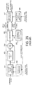
FIGRE 9 shows an arrangement of the conventional letterbox
image detection apparatus.
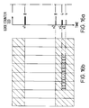
Initially, in the interests of simplification it is
assumed that a screen image having a uniform luminance like
a letterbox image without caption bands is provided. This
case of letterbox image is shown in FIGURE 30f, which has the
conventional 4:3 aspect ratio of TV receivers (here, no
caption bands are included).
The luminance signal of the screen image is applied to
the average value calculator 901. In response to the
horizontal sync signal and the vertical sync signal, a clock
pulse generator 902 generates a clear pulse (see FIGURE 30g)
for clearing the average value calculator 901 just before the
start of every field and an average value calculation range
pulse (see FIGURE 10h) for showing the effective image period
to the average value calculator 901. The average value
calculator 901 outputs the average of the luminance signal
level for each one-horizontal period (see FIGURE 30c).
The output from the average value calculator 901 is applied
to the input terminal of a 1H delay unit 903 and the noninverted
input terminal of a subtractor 904. On the other
hand, the output from the 1H delay unit 903 is applied to the
inverted input terminal of the subtractor 904. The
subtractor 904 calculates a difference by a subtraction, i.e.,
[luminance average of current line - luminance average of 1H
prior line], and supplies the calculated difference to one
input of a comparator 905 (see FIGURE 30b).
While the other input terminal of the comparator 905 is
supplied with an upper first threshold th1 (th1 has a positive
value) generated in a threshold generator 906 (see FIGURE 30b).
The comparator 905 provides an upper edge detection signal
detected in a predetermined column to the line position data
holder 907, when the difference is higher than the upper first
threshold th1. The comparator 905 also provides the lower
edge detection signal detected in a prescribed column to the
line position data holder, when the difference is lower than
the lower first threshold -th1.
A line position data generator 908 generates a line
position data corresponding to the vertical position data of
the screen image from the horizontal sync signal and the
vertical sync signal as its input, and supplies the line
position data to the line position data holder 907 (see FIGURE
30a).
The line position data holder 907 holds the line position
data which is found first at the field in regard to the upper
edge, and holds the line position data which is found last
at the field in regard to the lower edge. Accordingly, in
this case, the line position data hold in the line position
data holder 907 has a value v1 for the upper edge and a value
v2 for the lower edge, as shown in FIGURE 30a. These edges
indicate boundaries of the non-image areas and the central
main image, that is the top and bottom lines of the screen
image, which are operating normally.
The holding value of the line position data holder 907
is initialized to the invalid line position data value before
the effective image period of the field. Since the line
position data value remains the invalid line position data
value when the edge is not found, the holding value is
determined by the presence of the edge and the line position
data holding the vertical position data. When both top and
lower edge line position data holding values are valid, the
screen image of the field is determined as the letterbox image.
Next, it is assumed that a letterbox image with an
unchanged central main image and a caption band in a bottom
non-image area, e.g., a letterbox image as shown in FIGURE
30f containing a caption band. Here, the output from the
average value calculator 901 will be a waveform as shown in
FIGURE 30d.
Since the caption band has generally a higher luminance
level, the luminance level of the caption band often becomes
higher than the line average luminance level of the central
main image. In this case, as shown in FIGURE 30e, the upper
edge is normally detected as that of the main image at the
level of value v1. However, the lower edge is detected as
a lower edge of the caption band at the level of value v3,
but not the lower edge of the main image at the level of the
value v2.
According to this calculation, the caption band is
determined as it contained in the central main image, so that
it is impossible to operate the caption band moving function
for displaying the central main image operated by using the
caption band position data detector output (not shown) on a
full screen and the main circuit output, and for moving the
caption band to the central main image from the non image,
or the caption band compression function for relatively
compressing the caption band of the non image so as to display
the compressed caption band on the central main image.
If an approach of holding the edge position data before
the caption band is attempted, when a scene changes from a
4:3 aspect image to a letterbox image with a caption band,
the picture area top and bottom line of the former letterbox
image is not held so that following undesirable operations
will be occurred.
After the screen image with the caption band is displayed
on a full screen at the vertical position data, the screen
image changes to be displayed between the true picture area
top and bottom lines when the caption band disappears. Then
when the caption band is appear again the screen image changes
to the image display having the caption band again, so that
it is hard to see because of the repeated display change in
the short time.
Besides, since the edge is determined by the inter-line
difference of the line luminance average, a part of the screen
image where the luminance is high partially is detected as
the letterbox image incorrectly (see FIGURE 31), or an area
having an entirely low luminance moves in the lateral
direction is not detected as the letterbox image even it is
moving horizontally (see FIGURE 32).
Further, there is a problem that it is a letterbox image
but its top and bottom lines run across several lines not
parallel to the scanning line, so that it is not detected (see
FIGURE 33).
The conventional letterbox image detection apparatus has
a problem of wrongly detecting the letterbox image, when a
scene changes to an image having the luminance level of black
or close to it like a scene of the moon in the dark night or
when an image of high luminance level is superposed on the
center of an image of the luminance level of black or close
to it.
The conventional letterbox image detection apparatus has
also a problem that it can not detect the true top and bottom
picture area end data when there is the caption band, or
commits an error in discrimination of letterbox image or other
image for the images as shown in FIGURES 31 through 33.
It is, therefore, an object of the present invention to
provide a letterbox image detection apparatus, and more
particularly, a letterbox image detection apparatus which is
capable of preventing the erroneous letterbox image signal
detection when a scene changes to an image having the luminance
level of black or close to it or when an image of high luminance
level is superposed on the center of an image of the luminance
level of black or close to it.
Another object of the present invention is to provide a
letterbox image detection apparatus capable of detecting the
true top and bottom picture area end data even there is the
caption band.
It is a further object of the present invention to provide
a letterbox image detection apparatus capable of
discriminating whether the screen images as shown in FIGURES
31 through 33 are the letterbox image or not.
In order to achieve the above object, a letterbox image
detection apparatus for detecting a letterbox image by
detecting a boundary of an image area and a non-image area,
so as to display the image area on a full screen according
to the detection result but not to display the non-image area
according to first aspect of the present invention includes
timing pulse generating means for generating a timing pulse
for splitting one screen image into N columns (N is an integer
of 2 or more), image property calculation means for
calculating the image property of the N horizontal sections,
i.e., N columns split by the timing pulse generator,
inter-line difference calculation means for calculating the
inter-line difference of the N image properties, edge
detecting means for comparing the inter-line difference with
a predetermined upper first threshold th1 and for detecting
the edge, and edge position data holding means for holding
the vertical position data of the in-column edge detected by
the edge determinator.
A second aspect of the letterbox image detection apparatus
for detecting a letterbox image by detecting a boundary of
an image area and a non-image area, so as to display the image
area on a full screen according to the detection result but
not to display the non-image area having timing pulse
generating means for generating a timing pulse for splitting
one screen image into N columns (N is an integer of 2 or more),
first image property calculation means for calculating the
image property of the N columns (hereinafter referred to as
a column) split by the timing pulse generator, inter-line
difference calculation means for calculating the inter-line
differences of the image property for the N columns, edge
detecting means for detecting the edge by comparing the
inter-line difference with the upper first threshold th1,
edge counting means for counting in-column edges across one
screen image, M units of edge (M is an integer defined by 2
≤ M ≤ N ) vertical position data holding means for holding
the vertical position data where the corresponding edge is
detected last, second image property calculation means for
calculating the image property of the input image signal, edge
count threshold control means for changing the edge count
threshold to which M units of edge position data holding means
correspond in recponse to the second image property, and
vertical position data selecting means for selectively
outputting the vertical position data detected the highest
one of one or several vertical position data detected last
by the edge position data holding means.
A third aspect of the letterbox image detection apparatus
for detecting a letterbox image by detecting a boundary of
an image area and a non-image area, so as to display the image
area on a full screen according to the detection result but
not to display the non-image area, having timing pulse
generating means for generating a timing pulse for splitting
one screen image into N columns (N is an integer of 2 or more),
first image property calculation means for calculating the
image property of the N columns (hereinafter referred to as
a column) split by the timing pulse generator, inter-line
difference calculation means for calculating the inter-line
differences of the image property for the N columns, edge
detecting means for detecting the edge by comparing the
inter-line difference with the upper first threshold th1,
edge counting means for counting in-column edges across one
screen image, M units of edge (M i3 an integer defined by 2
≦ M ≦ N ) vertical position data holding means for holding
the vertical position data where the corresponding edge is
detected last, second image property calculation means for
calculating the image property of the input image signal, edge
count threshold control means for changing the edge count
threshold to which M units or edge position data holding means
correspond in response to the second image property, and
vertical position data selecting means for selectively
outputting the vertical position data detected the lowest
among one or several vertical position data detected first
by the edge position data holding means.
A fourth aspect of the letterbox image detection apparatus
for detecting a letterbox image by detecting a boundary of
an image area and a non-image area, so as to display the image
area on a full screen according to the detection result but
not to display the non-image area, having timing pulse
generating means for generating a timing pulse for splitting
one screen image into N columns (N is an integer of 2 or more),
first image property calculation means for calculating the
image property of each image levels of the N columns
(hereinafter referred to as a column) split by the timing pulse
generator, inter-line difference calculation means for
calculating the inter-line difference of the N image
properties, edge detecting means for detecting the edge by
comparing the inter-line difference with the upper first
threshold th1, vertical position data holding means for
holding the vertical position data of the edge detected by
the edge determinator, second image property calculation
means for calculating the predetermined image property of the
input image signal, and column numbers control means for
controlling the number of columns (N ) for splitting a screen
image according to the second image property.
A fifth aspect of the letterbox image detection apparatus
for detecting a letterbox image by detecting a boundary of
an image area and a non-image area, so as to display the image
area on a full screen according to the detection result but
not to display the non-image area, having timing pulse
generating means for generating a timing pulse for splitting
one screen image into N columns (N is an integer of 2 or more),
first image property calculation means for calculating the
image property of each image levels of the N columns
(hereinafter referred to as a column) split by the timing pulse
generator, inter-line difference calculation means for
calculating the inter-line difference of the N image
properties, edge detecting means for detecting the edge by
comparing the inter-line difference with the upper first
threshold th1, edge counting means for counting in-column
edges across one screen image, edge position data holding
means for holding the vertical position data when a count of
the in-column edges larger than the predetermined edge count
threshold are detected, edge position data holding means for
holding the horizontal position data when a count of the
in-column edges larger than the predetermined edge count
threshold are detected, edge position data updating means for
updating the position data holding means to a newly detected
edge position data when the corresponding edge counts more
than the edge counts held in the edge position data holding
means are detected in regard to the upper edge.
A sixth aspect of the letterbox image detection apparatus
for detecting a letterbox image by detecting a boundary of
an image area and a non-image area, so as to display the image
area on a full screen according to the detection result but
not to display the non-image area, having timing pulse
generating means for generating a timing pulse for splitting
one screen image into N columns (N is an integer of 2 or more),
first image property calculation means for calculating the
image property of each image levels of the N columns
(hereinafter referred to as a column) split by the timing pulse
generator, inter-line difference calculation means for
calculating the inter-line difference of the N image
properties, edge detecting means for detecting the edge by
comparing the inter-lino difference with the upper first
threshold th1, edge counting means for counting in-column
edges across one screen image, edge position data holding
means for holding the vertical position data when the
corresponding edge count are detected, edge position data
holding means for holding the horizontal position data of the
edge where the oorresponding edge count are detected, and edge
position data updating means for updating the edge position
data which is held in the edge position data holding means
and the edge position data which is held in the edge position
data holding means when the corresponding edge count about
the lower edge are detected, which are more than the edge count
held in the edge position data holding means.
A seventh aspect of the letterbox image detection
apparatus of the present invention includes means for
splitting a screen image into two or more columns, a first
detecting means for detecting a picture area in each column
split by the splitting means, a second detecting means for
detecting a sudden change of image in each column by checking
an inter-line correlation in each column split in a screen
image by the splitting means, a third detecting means for
detecting a caption band in each column split by the splitting
means, and an overall detector for finally detecting a
letterbox image signal.
Additional objects and advantages of the present
invention will be apparent to persons skilled in the art from
a study of the following description and the accompanying
drawings, which are hereby incorporated in and constitute a
part of this specification.
For a better understandings of the present invention and
many of the attendant advantages thereof, reference will now
be made by way of example to the accompanying drawings,
wherein:
The present invention will be described in detail with
reference to the FIGURES 1 through 22.
A first embodiment of the letterbox image detection
apparatus according to the present invention will be
described in reference to FIGURES 1 through 4.
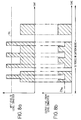
The first embodiment of the letterbox image detection
apparatus is explained in reference the screen images he same
images as used for explaining the conventional apparatus in
the case of letterbox image having the caption band, as shown
in FIGURES 30f and 2g.
In FIGURE 1, the luminance signal of the screen image is
applied to an edge determinator 101. The edge determinator
101 has a construction as shown in FIGURE 3.
To a clock pulse generator 102 the horizontal sync signal
and the vertical sync signal are input. And it outputs the
clear pulse for clearing an average value calculator 111 shown
in FIGURE 3 (see FIGURE 2e) and the average object interval
pulse (see FIGURE 2f) to the average value calculator 111 just
before starting the each column for splitting the screen image
into equal 8 columns. The average value calculator 111
outputs the average of the luminance signal levels for every
column.
Since the input signal to the letterbox image detection
apparatus is as same as the screen image explained in the
conventional example shown in FIGURE 30f, the uniform high
luminance area in the central main image has the same average
luminance as the conventional example. In FIGURE 2g the
boundaries of the columns are visualized by vertical solid
lines for convenience' sake of explanation.
The output from the average value calculator 111 is applied
to the input terminal of a one-horizontal period delay unit
(hereinafter referred to 1H delay unit) 113 and to the
non-inverted input terminal of a subtractor 114. On the other
hand, the output from the 1H delay unit 113 is applied to the
inverted input terminal of the difference device 114. The
subtractor 114 calculates a difference by a subtraction of
[luminance average of current column - luminance average of
prior column, and supplies the calculated difference to one
input terminal of a comparator 115.
While the other input terminal of the comparator 115 is
supplied with an upper first threshold th1 generated in a
threshold generator 116. The comparator 115 provides the
upper edge detection signal to an edge counter 103, as shown
in FIGURE 3, when the difference is higher than the upper first
threshold th1. While the comparator 115 provides a lower edge
detection signal to the edge counter 103, when the difference
is lower than a lower first threshold -thl.
The edge counter 103 counts the upper edges as detected
(see thick solid lines in FIGURE 2a) and the lower edges as
detected (see thick hollow lines in FIGURE 2a) for every screen
image. In the case of FIGURE 2, 8 counts of the upper edges
as detected are generated on the top of the main image, while
4 counts of the upper edges as detected are generated at the
top of the caption band. Similarly, 8 counts of the lower
edges as detected are generated on the bottom of the main image,
while 4 counts of the lower edges as detected are generated
at the bottom of the caption band.
A line position data generator 105 generates data
representing the position data of every line, i.e., every
horizontal scanning line, in response to the horizontal sync
signal and the vertical sync signal supplied thereinto. The
line position data generator 105 supplies the line position
data to three units of line position data holders 104 for
holding every line data for three sets of the top and bottom
lines of the main image. These line position data holders
104 are supplied with a valid edge detection signal, only when
any one of following three combinations of line features, i.e.,
a first combination of a line with 4 or more counts of upper
edges as detected and another line with 4 or more counts of
lower edges as detected, a second combination of a line with
5 or more counts of upper edges as detected and another line
with 5 or more counts of lower edges as detected, and a third
combination of a line with 6 or more counts of upper edges
as detected and another line with 6 or more counts of lower
edges as detected.
Each of the line position data holders 104 holds a first
occurrence of line position data in each field in regard to
the upper edge. While the line position data holders 104 each
holds a last occurrence of line position data in each field
in regard to the lower edge.
Accordingly, in this case, the line position data held
in each of the line position data holders 104 at the end of
a given field has the same value v1, as shown in FIGURE 30a,
in regard to the upper edge. In regard to the lower edge,
a line with 4 or more lower edges as detected has a line
position data of the value v3. Also a line with 5 or more
lower edges as detected and another line with 6 or more lower
edges as detected have the same line position data of the value
v2 (see FIGURES 2b, 2c and 2d). As to the set of line position
data corresponding to the line with 4 or more upper edge
detection signals and the other line with 4 or more lower edges
as detected are held, the line position data holders 104
temporarily holds the value v2, as shown in FIGURE 2b, in
regard to the lower edge. However, the line position data
is finally updated to the value v3, as shown by the arrow in
FIGURE 2b. Thus the last occurrence of line position data
is held in the line position data holders.
The data held in the three sets of the line position data
holders 104 are initialized to predetermined distinguishable
from the valid line position data prior the start of every
field. When a line with specified counts of edge detection
signal are not found, the data in the line position data
holders 104 are kept to a predetermined value.
These line position data held in the line position data
holders 104 are supplied to a picture area end detector 106.
The line position data which is valid and can hold the largest
count of edges among the three sets of the upper edge holding
lines is selected. That is, the valid and the biggest line
position data is selected among the three sets of the upper
edge holding lines. Then, the valid and lowest line position
data is selected among three sets of the lower edge holding
lines.
In the embodiment of FIGURE 2, the value v1 is selected for
the upper edge position data. While the value v2 is selected
for the lower edge position data, not but the value v3. These
selected line position data are showing the boundary of non
picture and the main image, that is the top and bottom line
position data of the picture area.
Accordingly, in the picture area end detector 106, when
the selected top and lower edge line position data holding
values are both valid the field is determined to have a
letterbox image.
According to the operation described above, true top and
bottom picture area end data are obtained without mistaking
the bottom line of the caption band as the bottom picture edge.
In this embodiment, three sets of edge count thresholds, i.e.,
4 or more edges, 5 or more edges and 6 or more edges are selected
as the count of edges. However, other count of edges may be
selected,
Further, while the same edge count thresholds are selected
for determining the upper and bottom edges of picture area,
to both top and bottoms, the edge count thresholds may be
different from each other. And, in this embodiment, it is
explained by the embodiment of 8 columns splitting, however,
the count of columns may be changed.
In this embodiment, the input image is explained in the
case that it has edges over 8 columns at the top and bottom
picture area end data as shown in FIGURE 2g. However, in
general case that the count of the in-column edges on the true
picture area top and bottom lines are more than that on the
caption band in the screen image, the true top and bottom
picture area end data are obtained by properly setting the
edge count thresholds and the number of their units.
And, in this embodiment, the average luminance is used
as the image property of the inter column image, however, other
values such as a median may be used as the image property.
Further, the edge determinator 101 may be constructed as
shown in FIGURE 4. In FIGURE 4, the I luminance signal and
Q luminance signal of the screen image as inputs change to
the absolute values in an absolute value calculators 117 and
118. These absolute value outputs are both added in an adder
119, and its average in the column is taken in an average value
calculator 111b in the same way as the luminance signal
processing shown in FIGURE 3. Then the inter-line difference
is taken in a 1H delay unit 113b and a subtractor 114b, and
the inter-line difference is compared with a second threshold
th2 generated in a threshold generator 116b. When the
inter-line difference is higher than the second upper
threshold th2 (> th2), it is determined that there is an
in-column upper edge based on the luminance signal. When the
inter-line difference is lower than the second lower
threshold th2 (< -th2), it is determined that there is an
in-column lower edge based on the luminance signal.
The determination result is operated an OR logic with the
luminance signal processing based in-column edge
determination signal, as shown in FIGURE 3, for outputting
an in-column edge determination signal from the edge
determinator 101.
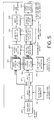
A second embodiment of the letterbox image detection
apparatus according to the present invention will be
described in reference to FIGURES 5 through 8. In FIGURE 5,
the same components as those shown in FIGURE 1 are assigned
with the same marks, and the detail explanation will be
omitted.
The luminance signal of the screen image is applied to
one input terminal of a nonlinear processor 207. The
nonlinear processor 207 is an amplitude limiter which outputs
the luminance signal without limiting when a logic level "1"
is applied, while limiting the luminance signal lower than
a third threshold th3 when a control data "0" is applied.
The edge determinator 101, the clock pulse generator 102,
the edge counter 103, the line position data holders 104, the
line position data generator 105, and the picture area end
detector 106 operate in the same way as those of the first
embodiment in response to the output from the nonlinear
processor 207. As explained in the first embodiment, the
picture area end detector 106 outputs the letterbox image
determination result of the top and bottom picture edge and
field unit.
Three units of edge position data holders 208 correspond
in a one-to-one relationship with the three units of the line
position data holders 104 for adapting with the edge count
thresholds, i.e., the 4 or more edge counts, the 5 or more
edge counts and the 6 or more edge counts, respectively.
Every when each of the line position data holders 104 is
updated by the line position data, each of the edge position
data holders 208 is updated by the in-column edge's horizontal
position data across one horizontal period.
To be more concrete, about the upper edge, all of more
than 4, more than 5, and more than 6 hold the horizontal
position data of the edge of v1 line. On the other hand, about
the lower edge, at first more than 4, more than 5, and more
than 6 hold the horizontal position data of the edge of v2
line. However, since only four count of the in-column edges
are detected at the v3 line, it updates the horizontal position
data held in the edge holders 208 associated with the line
position data holders 104 of the lower edge more than 4 from
(11111111) to (00111100).
The picture edge selector 209 outputs the edge position
data corresponding to the count of edges determined in the
picture area end detector 106 by the edge position data held
in the edge position data holder 208 as its input.
A picture edge fluctuation detector 210, having the top
and bottom picture edge that is the output from the picture
area end detector 106 and the determination result as its input,
clears the edge horizontal position data accumulated in an
edge data accumulator 213 when the inter-line differences of
the top and bottom image picture lines of field and the top
and bottom picture edge of one field before are higher than
the fourth threshold th4, but it does not clear the edge
horizontal position data when these inter-line differences
are lower than the fourth threshold th4.
Further, the picture edge fluctuation detector 210
outputs a "0" logic level representing that the fluctuation
of the picture edge is great when the inter-line differences
of the top and bottom piature area end data of the field and
the top and bottom lines of one field before are higher than
the fifth threshold th5, and it outputs a "1" logic level
representing that the fluctuation is small when the
inter-line differences are lower the fifth threshold th5.
A stability determinator 211 detects that it is stable
when the input of the top and bottom picture area end data
fluctuation detection result is always kept in the value "1"
for a specific fields so as to supply the value "1" to a stable
edge data holder 212.
It detects that the edge is unstable when the fluctuation
detection result of either the top or the bottom picture edge
is in the value "0" in any field so as to supply the value
"0" to the stable edge data holder 212.
The stable edge data holder 212 obtains the current top
and bottom picture area end data from the picture area end
detector 106 when the stability detection result has the "1"
logic level and updates the top and bottom stable picture area
end data. In the other way, it holds the top and bottom stable
picture area end data without updating them when the stability
detection result has a "0" logic level.
On one hand that the updated top and bottom stable picture
area end data are output, a picture area indicating signal
having the "1" level across the picture area and top and bottom
α-length areas is supplied to the control terminal of the
nonlinear processor 207 (see FIGURE 7b).
According to this operation, the image signal is
suppressed its amplitude for portions outside the top and
bottom stable picture end lines (see FIGURE 7c). Accordingly,
once the stable top and bottom picture area ends are set up,
it controls the amplitude limit to the extent not to generate
any in-column edge determination signal at the vertical
position data even if the horizontally extending caption band
having high luminance appears. So that the top and bottom
picture area ends will be stably detected.
Here, the amplitude limiter is used as the nonlinear
processor 207. However, the same effect may be obtained by
using a level converter for converting levels of a pixel having
a level higher than a predetermined threshold thj and its
laterally neighboring pixels having levels higher than a
predetermined level 1im to the level 1im.
Here, the picture edge fluctuation detector 210, the
stability determinator 211, and the sable line holder 212 may
be operated by the flame unit.
The edge data accumulator 213 accumulates logical ORs of
position data of edge representing lines in every field until
it being cleared by a clear signal applied from the picture
area end fluctuation detector 210. The edge data accumulator
213 then provides the edge representing line position data
to an edge detector 214 for period of the picture area end
being stabilized (the accumulation of edge present).
The edge detector 214, which counts horizontal position
data of the edge, outputs the "1" logic level representing
that top and bottom stable lines are valid when it is higher
than a sixth threshold th6, but outputs "0" logic level
representing that the stable picture area end data are invalid
when it is lower the sixth threshold th6.
The operations of the edge data accumulator 213 and the
edge detector 214 will be explained in case that the bright
part moves from right to left on the screen as shown in FIGURE
32. As shown in FIGURE 34, if the output from the picture
edge selector 209 is taken as shown in FIGURE 34a, the logic
level "1" representing the in-column edge moves from left to
right with the passage of time. Accordingly, the storing
value after updating will be changed as c, and edge detector
214 outputs as valid when the count of accumulated "1" logic
levels exceeds the sixth threshold th6 (=6).
Accordingly, even when for instance the count of in-column
edges by field unit are relatively small like 4, and the edge
detector can not determine as the edge only by the edge count
in its field, it can determine that there are plenty of edges
when the accumulation is higher than the sixth threshold th6.
In the above explanations, the edge position data holders
208 are associated in a one-to-one relationship with the line
position data holders 104. However, the edge position data
holders 208 may be arranged to hold not only the in-column
edge's horizontal position data for the line with the
subjective count of the in-column edges but also the in-column
edge's horizontal position data for other vertical
neighboring lines. While the picture edge selector 209 may
be arranged to output both of the column presence horizontal
position data may be output both of the in-column edge's
horizontal position data for the line with the subjective
count of the in-column edges and the in-column edge's
horizontal position data for other vertical neighboring lines.
Also the edge data accumulator 213 may be arranged to calculate
an OR logic of those in-column edge's horizontal position data.
In this construction, the case that the boundary of the central
main image and the non image is not parallel to the scanning
line is able to be detected as the letterbox image system.
As explained above, even the screen image that is not able
to be determined as the letterbox image system by only the
single field (for instance FIGURE 32), or the screen image
which boundary of the central main image and the non image
slightly incline in unparallel to the scanning line (for
instance FIGURE 33) can be determined as the letterbox image
system if the edge is detected by the count of the accumulated
edges.
The present invention is explained in the logic circuit
like by using above two embodiments. As a matter of course,
it is possible to be constructed by the program software such
as the microcomputer or DSP (Digital Signal Processor).
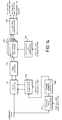
A third embodiment of the letterbox image detection
apparatus according to the present invention will be
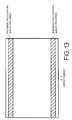
described in reference to FIGURES 9 through 13. In FIGURE
9, the same components as those shown in the first and the
second embodiments shown in FIGURES 1 and 5 are assigned with
the same marks and detail explanation will be omitted.
The luminance signal component of the image signal is
applied to the nonlinear processor 207. The output from the
nonlinear processor 207 is applied to the edge determinator
101.
The clock pulse generator 102 taking the vertical sync
signal and the horizontal sync signal as its input generates
the clear pulse mentioned above (see FIGURE 2g) and the average
value calculation range pulse (see FIGUARE 2f) and supplies
them to the other input terminal of the edge determinator 101.
The edge determinator 101 takes the inter-line difference
of each column which is split the valid image interval of the
one-horizontal period into 8, so as to determine the presence
of the top and lower edge of each column.
This top and lower edge determination results are applied
to the edge counter 303 and the edge position data holder
308.
The edge counter 303 counts the in-column edges across
one-horizontal period, and then supplies "1" logic levels to
the edge count threshold controller 316 when there are three
or more in-column edges, four or more in-column edges, five
or more in-column edges, fix or more in-column edges, or seven
or more in-column edges, respectively.
On the other hand, the luminance component of the image
signal is also applied to the average value calculator 315.
The average value calculator 315 calculates the average
luminance level of the central main image of the 4:3 aspect
screen which is corresponding to the central main image of
the letterbox screen as shown in FIGURE 30, so as to update
the value to the vertical (hereinafter referred to as V)
blanking period and supplies the value to the edge count
threshold controller 316.
The edge count threshold controller 316 changes the edge
count threshold according to the output from the average value
calculator 315. FIGURE 11 is a flowchart for explaining the
operation of the edge count threshold controller 316.
The edge count threshold controller 316 is applied with
five kinds of edge count results such as more than 3, more
than 4, more than 5, more than 6, and more than 7.
When the output from the average value calculator 315 is
more than the threshold th7 (in case of YES of ST111) the
central main screen image is determined to blight, four kinds
of larger edge counts, i.e., counts more than 4, more than
5, more than 6, and more than 7 among the five kinds of the
resultant edge count are selectively output.
When the output from the average value calculator 315 is
lower than the threshold th7 the central main screen image
is determined to the dark (in case of the NO branch from ST111),
four kinds of smaller edge count, i.e., counts of more than
3, more than 4, more than 5, and more than 6 among the five
kinds of the resultant count are selectively output.
As shown in FIGURE 12, the line position data holder 304
and the edge position data holder 308 correspond with each
other in a one-to-one relationship according to the count of
the in-column edges.
The line position data holders 304a through 304d and the
edge position data holders 308a through 308d newly hold the
line position data and the horizontal position data of the
edge-occurring column when the upper edge-occurring
horizontal has initially come in every field. According to
this operation, it can hold position data of the highest line
where each count of in-column edges is occurred and the
horizontal position data corresponding to the count of
in-column edges at that time.
Further, if the edge corresponding to the edge count is
not generated over the one field interval the invalid line
position data which is initialized at the V blanking ending
time is remain in the line position data holder 304.
The line position data holders 304e through 304h and the
edge position data holders 308e through 308h newly hold the
line position data and the horizontal position data
corresponding to the count of in-column edges in every time
when it comes to the horizontal line whereon prescribed count
of in-column edges are detected for every fields. According
to this operation, it can hold position data of the lowest
line where each count of in-column edges is occurred and the
horizontal position data corresponding to the count of
in-column edges at that time.
Further, if the edge of the picture area with corresponding
count of in-column edges is not generated across every one
field, a predetermined line position data which has been
initialized at the end of a vertical blanking period remains
in the line position data holder 304.
The picture edge detector 306 determines the biggest line
position data about the upper edge and the smallest line
position data about the lower edge among each top and bottom
four kinds of line position data output from the line position
data holder 304.
And, the picture edge detector 306 supplies a signal
associated with the line position data which resulted in the
determine output to the picture edge selector 309.
The picture edge selector 309 provided with the output
from the picture edge detector 306 selects the edge horizontal
position data corresponding to the edge position data holder
308 and supplies the data to the edge data accumulator 213.
The following operations will be same as that explained
for the second embodiment.
The operation mentioned above will be further explained.
when the central main screen image is high luminance, the edge
count in interest will be increased to such as 4 edges through
7 edges. When the central main screen image is high luminance
a great number of edge will be expected.
Since it does not sense toward to the caption band or
picture area containing smaller edge counts than expected
such as less than three in one-horizontal period, so as to
reduce the wrong operation.
On the other hand, when the central main screen image is
low luminance the upper first threshold th1 for the edge
detection does not reduced, but the edge count will be reduced
to 3 through 6.
So when the central main screen image is low luminance, a
great number of edge is not expected, however, since the upper
first threshold th1 for the edge detection remains as it is
the edges are certainly generated.
Accordingly, if the edges occupy the most part of the
horizontal period as the accumulated count of in-column
edgeseven if the edges are relatively small in number, edges
will be determined to be existed, and efficiency will be
maintained toward the low luminance. In this embodiment, the
sets of the edge number in interest are 4 through 7, and 3
through 6, however, the sets are not limited to these sets
mentioned above, but these may be other sets.
Further, the central main screen image is selected as the
area subjected to the average value calculator 315, however,
the several lines around the screen top and bottom which is
always non screen area at the letterbox image input time may
be the average value calculation subjected area (see FIGURE
13).
When the output from the average value calculator 315 is
a big value, since the level of the non image is determined
to be raised it can reduce the wrong operation by the great
count of the in-column edges. On the other hand, when the
output is a low value it can maintain the efficiency by the
making the count of in-column edges a little bit smaller.
If the level is ranged uniformly when the average level
of the central main image is high the count of in-column edges
of the true edge line will be expected to be a great in number.
At this time, the threshold of the count of in-column edges
which is needed for determining to be the edge line is made
to be high value. So that the caption band separation ability
will be high as shown in the embodiment mentioned above.
A fourth embodiment of the letterbox image detection
apparatus according to the present invention will be
described in reference to FIGURE 14. In FIGURE 14, the same
components as those shown in the first embodiment shown in
FIGURE 1 are assigned with the same marks.
The luminance component of the image signal is applied
to the average value calculator 407 and the edge determinator
101. The average value calculator 407 calculates the average
of the luminance component input as objecting around the
central main screen image shown in FIGURE 10, holds the average
for a vertical blanking interval, and outputs the value in
a following field interval.
The output from the average value calculator 407 is applied
to the column numbers controller 408. The column numbers
controller 408 determines that the luminance is enough when
the input average is more than the threshold th8, so as to
output a "1" logic level to the clock pulse generator 402.
In response to the "1" logic level, the clock pulse
generator 402 generates a clock pulse for splitting the screen
image into 8 columns.
On the other hand, the column numbers controller 408
determines that the luminance is not enough when the input
average is less than the threshold th8, and generates a "0"
logic level to the clock pulse generator 402.
In response to the output "0", the clock pulse generator
402 generates a clock pulse for splitting the screen image
into a smaller number of columns, e.g., four columns which
is smaller than those for a screen with an enough luminance.
According to the operations mentioned above, the column
numbers in case of the low luminance near the central main
screen image is made to be smaller than the column numbers
in case of the high luminance, so that the numbers of pixel
in every column at the low luminance level are increased and
also an S/N (signal/noise) ratio will be improved.
Here, it is mentioned about the horizontal luminance level
around the central main screen image. However, it may be the
noise level related to the one through several lines which
will be the non image part of the screen top and bottom part
letterbox image input time, so as to be the column numbers
controller 408 for controlling to reduce the column numbers
when the noise level is high by changing the horizontal value
calculator 407 to the noise level calculator.
A fifth embodiment of the letterbox image detection
apparatus according to the present invention will be
described in reference to FIGURES 15 and 16. In FIGURE 15,
the same components as those shown in the first and second
embodiments shown in FIGURES 1 and 5 are assigned with the
same marks, and the detail explanation will be omitted.
The luminance signal of the screen image is applied to
the one input terminal of the nonlinear processor 207. The
edge determinator 101, the clock pulse generator 102, the edge
counter 103, the line position data holders 104, and the line
position data generator 105 are operated in the same manner
as the first embodiment in response to the output from the
nonlinear processor 207.
If both of the top and bottom picture area end data held
in the line position data holder 104 applied to the line
position data determinator 516 are valid, the line position
data determinator 516 determines the input screen image as
a letterbox image.
A single unit edge position data holder 508 associated
in a one-to-one relationship with the single unit line
position data holder 104 is updated by the in-column edge's
horizontal position data across one-horizontal period from
the edge determinator 101. In more concrete, the edge
position data holder 508 receives an update instruction
signal from an edge position data updater 515 as described
later.
The operations of the edge position data holder 508, the
edge position data updater 515, and the line position data
holder 104 will be explained.
It is assumed that the count of the in-column edges of
the edge position data updater 515 are 4 through 7. It is
also assumed that a 4:3 aspect screen image, as shown in FIGURE
16 (the same as the image shown in FIGURE 2) has been applied
thereto. At near the every vertical blanking end, that is
the time before the screen top end shown in FIGURE 16b, the
line position data holder 104 is initialized to the invalid
line position data and the edge position data holder 508 is
initialized to the "0" logic level.
About the output from the edge counter 103 (see FIGURE
16a), when the vertical position data comes to v1, the count
of the upper in-column edges reaches a count of 8 for the first
time.
At that time, the eight count of the in-column edges are
counted in the edge counter 103 in regard to the upper edge,
while a zero count of the in-column edges are held in the edge
position data holder 508 in regard to the lower edge. When
these counts are compared, the count in the edge counter 103
is higher than the count in the edge position data holder 508.
Accordingly, since it meets the edge position data
updating condition (current count of upper in-column edges)
> (the count of upper in-column edges held in the edge position
data holder 508), the edge position data updater 515 supplies
the control signal instructing the updating to the line
position data holder 104 and the edge position data holder
508.
The line position data holder 104 holds the current line
position data from the line position data generator 105 in
response to the control signal,.
Further, the edge position data holder 508 is updated to
the current horizontal array of in-column edge data
(11111111) output from the edge determinator 101, in response
to the control signal.
When the vertical position data comes to v2, the edge
counter 103 will come to count 8 counts of lower in-column
edges. When the vertical position data comes to v1, the edge
counter 103 (see FIGURE 16a) comes to count 8 counts of the
upper in-column edges for the first time. At that time, the
count of lower in-column edges of the edge counter 103 is 8
and the count of lower in-column edges held in the edge
position data holder 508 has the "0" logic level in regard
to the lower edge. Accordingly, when these counts are
compared with each other, the current count of the edge counter
103 is larger than the count held in the edge position data
holder 508.
Accordingly, the above case meets the edge position data
updating condition; (count of current lower in-column edges
≧ count of lower in-column edges held in the edge position
data holder). Then the edge position data updater 515
supplies an update instruction signal to the line holder 104
and the edge position data holder 508.
The line position data holder 104 holds the current line
position data from the line position data generator 105 in
response to the control signal.
Further, the edge position data holder 508 is updated to
the current horizontal array of in-column edge data
(11111111) output from the edge determinator 101, in response
to the control signal. For instance, as to the vertical
position data from then on, when the count of the in-column
edges held in the edge position data holder 508 is larger than
the count of the in-column edges output from the edge counter
103, the edge position data updater 515 supplies the update
instruction signal to the line position data holder 104 and
the edge position data holder 508.
When the vertical position data comes to v4, it reaches
the upper edge of the caption band. At that time, the count
of upper in-column edges output from the edge counter 103 are
4 counts and the horizontal array of upper in-column edge data
is (00111100).
On the other hand, the count of the upper in-column edges
held in the edge position data holder 508 are 8 and the count
is larger than the count of upper in-column edges at the
vertical position of the v4. This case however does not meet
the updating condition, so that the edge position data updater
515 does not output the update instruction signal to the line
position data holder 104 and the edge position data holder.
When the vertical position data comes to v3, it reaches
the lower edge of the caption band.
At that time, the count of lower in-column edges output
from the edge counter 103 are 4 counts and the horizontal array
of upper in-column edge data is (00111100).
On the other hand, the count of the lower in-column edges
held in the edge position data holder 508 are 8 and the count
is larger than the count of lower in-column edges at the
vertical position of the v3. This case however does not meet
the updating condition, so that the edge position data updater
515 does not output the update instruction signal to the line
position data holder 104 and the edge position data holder.
When the line position data has been eventually held in
the line position data holder 104 at the end of one field period,
the upper edge of the picture area presents on the vertical
position v1. While the lower edge of the picture area
presents on the vertical position v2. These data of the upper
and lower picture area edges are then supplied to next stages
such as the picture edge fluctuation detector 210. The edge
horizontal position data to be supplied to the edge data
accumulator 213 has a horizontal array of upper in-column edge
data (11111111) and a horizontal array of lower in-column edge
data (11111111). Accordingly, the true top and bottom lines
of the picture can be detected without receiving affections
due to the caption band. The operations from then on are same
as those in the embodiment mentioned before.
Here, in regard to the edges of the picture area, any one
of the top and lower edge lines may be calculated.
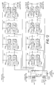
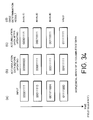
A sixth embodiment of the letterbox image detection
apparatus according to the present invention will be
described in reference to FIGURES 17 through 20.
In FIGURE 17, reference numerals 11, 12 denote input
terminals to which a luminanae signal a1 and a chrominance
signal b1 separated from an image signal are supplied from
an external input terminal or a channel selector/demodulator
circuit. The luminance signal a1 and the chrominance signal
b1 led to these input terminals 11, 12 are then supplied to
a column splitter 13.
The column splitter 13 splits a screen image into several
columns, calculates an average luminance level and an average
chrominance level in a division unit and supplies data c1 of
this calculated result to a normal aspect image detector 14
and an edge determinator 15. Further, the column splitter
13 detects how many signals seemed to be caption bands are
there per division in a split unit and supplies the data d1
to a caption band detector 16. The normal aspect image
detector 14 has an average luminance detecting means and an
average chrominance level detecting means, and by checking
size of an average luminance level and an average chrominance
level from the data c1, detects a column containing a picture
area and outputs the start point and the end point of picture
area as a line position data e1.
The edge determinator 15 is a circuit for detecting a sharp
edge between the non-image area and the main image across a
screen image, which is a feature of a letterbox image and
outputs a sharp edge indicating signal f1 indicating the
presence or absence of a sharp edge, and also the position
data of upper and lower edges as line position data g1. In
this case, the edge determinator 15 has average luminance
detecting means and average chrominance level detecting means
and furthermore, a holding means for holding information of
one or more prior detection results and comparing means for
comparing the detection results held in the holding means with
the current detection results.
The caption band detector 16 compares the count of signals
A that are seemed to be caption bands shown by data d1 supplied
from the column splitter 13 with a specified value B and when
the aount of signals A that are seemed to be caption bands
is more than the specified value B, regards that there are
caption bands and otherwise, there is no caption band and in
the case where there are caption bands, outputs a caption band
final line signal h1.
An overall determinator 17 checks the detection results
from the normal aspect image detector 14, the edge
determinator 15 and the caption band detector 16 to finally
determine whether an input image signal is completely a
letterbox image signal or a normal aspect image signal. If
it is unable to make the determination, the overall
determinator 17 determines that the judgment is unable and
then generates a "letterbox image/normal aspect
image/undeterminable" determining signal il from its output
terminal 18. Further, when an input signal completely has
an feature of letterbox image signal, the overall
determinator 17 generates a line position data kl for
providing the picture area start and end position data from
its output terminal 20. Further, in case of a letterbox image,
it is determined whether there is a caption band outside the
main image. When such a caption band is detected, a signal
jl indicating a presence of caption band is output from the
output terminal 19. Further, when there is a caption band,
the final caption band position data is supplied to an output
terminal 20 as the line position data kl.
In such the construction as described above, the column
splitter 13 becomes means for splitting the screen image into
two or more columns, the normal aspect image detector 14, i.e.,
first detecting means for detecting a picture area in each
column split by the splitting means, the edge determinator
15, i.e., second detecting means for detecting sudden change
of image in each column by checking an inter-line correlation
in each column split by the splitting means, the caption band
detector 16, i.e., third detecting means for detecting a
caption band in each column split by the splitting means has
means for counting high luminance pixels and low luminance,
and the overall determinator 17, i.e., a determinator for
determining whether an image signal is a letterbox image
signal in response to the detection results from the first
through third detecting means.
As an overall operation of a wide aspect TV receiver, if
the "letterbox image/normal aspect image/undeterminable"
determining signal il indicates a complete letterbox image
signal when checking the output from the letterbox image
detection apparatus, a picture being displayed on the screen
is vertically expanded according to the start and end position
data of a picture area shown by the line position data kl.
Further, if both of the "letterbox image/normal aspect
image/undeterminable" determining signal il and the caption
band determining signal j1 indicate that there is a right
letterbox image signal accompanying a caption band, the
screen image is vertically expanded to the range wherein the
caption band remains on the bottom end of the screen. If the
"letterbox image/normal aspect image/undeterminable"
determining signal i1 indicates the complete normal aspect
image signal, the vertical expansion is released to the
original state. If the "letterbox image/normal aspect
image/undeterminable" determining signal il indicates the
judgment is impossible, the current screen image is
maintained.
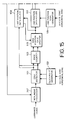
The operation of the letterbox image detection apparatus
will be described in reference to FIGURES 18 through 20.
FIGURE 18 is an explanatory diagram showing the column
splitting by the column splitter 13 shown in FIGURE 17.
The column splitter 13 shown in FIGURE 17 splits a screen
21 into several columns (8 columns in case of FIGURE 18) and
obtains an average luminance level and average chrominance
level in each of the split columns.
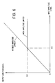
FIGURE 19 is an explanatory diagram showing a first example
of the detection by the letterbox image detection apparatus
shown in FIGURE 17, and FIGURE 19a shows the display on the
4:3 aspect screen and FIGURE 19b shows the display on the 16:9
aspect screen.
In FIGURE 19, it is assumed that the letterbox image
detection apparatus is in a case where a scene was changed
from a vertically expanded Imago which was a letterbox image
to a scene of the moon in the dark night which was a normal
aspect image. This is a scene which could not be determined
as a normal aspect image according to conventional detection
method subjected for whole of the screen image. In this
embodiment, as one horizontal period is split into 8 columns
and average luminance and average chrominance levels in every
split columns are obtained, an average luminance and
chrominance levels for one of the split columns across one
screen image exceed a threshold for determining a presence
or non-presence of images (threshold for determining a normal
aspect image) immediately after the scene of the moon in the
dark night appears as shown in FIGURE 19a. At the time of
exceeding the picture presence/non-presence determining
threshold, the normal aspect image detector 14 instantly
determines that there is a picture area end on that line and
gives an instruction to the main microcomputer side of a TV
receiver to display the picture at least up to the upper edge
of the picture area and therefore, for instance, when a picture
is displayed on the 16:9 aspect screen as shown in FIGURE 19b,
the vertical expansion is released and no image chipping
occurs on the displayed picture.
FIGURE 20 is an explanatory diagram showing the second
example of the detection of the letterbox image detection
apparatus shown in FIGURE 17, FIGURE 20a shows the display
on the 4:3 aspect screen and FIGURE 20b shows the display on
the 16:9 aspect screen.
In FIGURE 20, it is assumed that the letterbox image
detection apparatus is in a case where a scene was changed
from the normal aspect image (the normal aspect display) to
a scene appearing the Sun at the center. In the conventional
detection method subjected for whole of screen image, such
a screen image satisfies the features of a letterbox image
and thus erroneously operates. However, in the embodiment
of this invention, as one horizontal period is split into 8
columns and average luminance and chrominance levels of each
column are obtained, the normal aspect image detector 14 gives
such information that "There is no-picture area and a portion
seems to be the main image but there is no picture area
throughout one horizontal period" to the overall determinator
17. The overall determinator 17 examines this determination
result and determining that the picture is seemed not a normal
aspect image but does not satisfy the conditions for a
letterbox image, outputs a determining impossible signal.
In the case when the determining is not possible, in order
to maintain the preceding condition as described above, if
a picture is displayed on the 16:9 aspect screen as shown in
FIGURE 20b, the normal aspect display is continued. So, such
an image chipping as seen in the conventional example does
not occur.
The explanation of caption band detecting operation will
be omitted in this explanation but the caption band detecting
performance is increased when a caption band is detected by
splitting a screen image into several columns in the caption
band detecting operation.
According to the embodiment of the present invention,
since the normal aspect image detector 14, the edge
determinator 15 and the caption band detector 16 detect a
picture area, a sudden change of image and a caption band in
each column split by the column splitter 13 by checking an
inter-line correlation in each column, it is possible to
prevent erroneous operations in the letterbox image signal
detection if a scene has changed to an image having entirely
a low luminance are close to black level or an image having
a surrounding low luminance area close to the black level and
a centralized high luminance area. Thus, it is possible to
give a favorable impression to user.
A seventh embodiment of the letterbox image detection
apparatus according to the present invention will be
described in reference to FIGURE 21.
In FIGURE 21, a column/row block splitting fashion changer
30 is a column splitting fashion changing means and have a
column/row block splitter 33, which becomes a splitting means,
change to another column splitting fashion. In this case,
the column/row block splitting fashion changer 30 controls
the column/row block splitter 33 so as to further split a
column, that is desirable to see further in detail, to further
smaller columns.
The circuit configuration of the column/row block
splitter 33 other than this is the same as the column splitter
13 shown in FIGURE 17.
FIGURE 22 is an explanatory diagram showing the operation
of the embodiment shown in FIGURE 21.
In FIGURE 22, each column on a screen image 40 is further
split into several row bleaks in the vertical direction.
Initially, by changing the column/row block splitting fashion
for coarse row blocks under the control of the column/row block
splitter 33, the edge determinator 15 carries out a rough check
in the vertical direction for seeking in-column edges, i.e.,
part of picture area ends such as edges of main image and
caption bands. After that, a row block wherein any result
of the check has occurred is further split into several fine
sub-row blocks through the control of the column/row block
splitter 33 for fine seeking of picture areas. A similar
operation is also applied for detecting the upper and lower
edges. By these operations, it is possible to reduce the
total amount of data to be processed.
Although, in the embodiments as shown in FIGURES 17 through
22, the normal aspect image detector 14 as the first detecting
means, has both of the average luminance level detecting means
and the average chrominance level detecting means, the normal
aspect image detector 14 is sufficient if it has at least one
of the average luminance level detecting means and the average
chrominance level detecting means.
Further, although in the embodiments as shown in FIGURES
17 through 22, the edge determinator 15 as the second detecting
means has both of the average luminance level detecting means
and the average chrominance level detecting means, the edge
determinator 15 is sufficient if it has at least one of the
average luminance level detecting means and the average
chrominance level detecting means.
As described above, the present invention can provide an
extremely preferable letterbox image detection apparatus.
According to the present invention as described above,
since it detects edges in columns splitting a screen image
according to the edge count in the one-horizontal period after
determining the presence or absence of edge as to the columns
split horizontally, it is able to easily and accurately
performs the letterbox image detection which was hard to
detect in the conventional way.
Further, about the screen images shown in FIGURES 31
through 33 it is possible to detect if it is the letterbox
image system or not.
According to the present invention, it is possible to
prevent the erroneous operation in the letterbox image signal
detection when a scene changed to a scene of black luminance
level or close to it or when an image of high luminance level
is superposed on the center of an image of black luminance
level or close to it and it is therefore possible to give a
favorable impression to user.
While there have been illustrated and described what are
at present considered to be preferred embodiments of the
present invention, it will be understood by those skilled in
the art that various changes and modifications may be made,
and equivalents may be substituted for elements thereof
without departing from the true scope of the present invention.
In addition, many modifications may be made to adapt a
particular situation or material to the teaching of the
present invention without departing from the central scope
thereof. Therefor, it is intended that the present invention
not be limited to the particular embodiment disclosed as the
best mode contemplated for carrying out the present invention,
but that the present invention includes all embodiments
falling within the scope of the appended claims.
The foregoing description and the drawings are regarded
by the applicant as including a variety of individually
inventive concepts, some of which may lie partially or wholly
outside the scope of some or all of the following claims. The
fact that the applicant has chosen at the time of filing of
the present application to restrict the claimed scope of
protection in accordance with the following claims is not to
be taken as a disclaimer or alternative inventive concepts
that are included in the contents of the application and could
be defined by claims differing in scope from the following
claims, which different claims may be adopted subsequently
during prosecution, for example, for the purposes of a
divisional application.