EP0837026A1 - A handrail mechanism for a variable speed moving sidewalk - Google Patents
A handrail mechanism for a variable speed moving sidewalk Download PDFInfo
- Publication number
- EP0837026A1 EP0837026A1 EP97122730A EP97122730A EP0837026A1 EP 0837026 A1 EP0837026 A1 EP 0837026A1 EP 97122730 A EP97122730 A EP 97122730A EP 97122730 A EP97122730 A EP 97122730A EP 0837026 A1 EP0837026 A1 EP 0837026A1
- Authority
- EP
- European Patent Office
- Prior art keywords
- moving
- handrail
- portions
- guiding plate
- speed
- Prior art date
- Legal status (The legal status is an assumption and is not a legal conclusion. Google has not performed a legal analysis and makes no representation as to the accuracy of the status listed.)
- Granted
Links
- 238000007664 blowing Methods 0.000 claims description 3
- 230000001133 acceleration Effects 0.000 claims description 2
- 238000005096 rolling process Methods 0.000 claims description 2
- 210000000078 claw Anatomy 0.000 description 1
- 230000007547 defect Effects 0.000 description 1
- 238000005516 engineering process Methods 0.000 description 1
Images


Classifications
-
- B—PERFORMING OPERATIONS; TRANSPORTING
- B66—HOISTING; LIFTING; HAULING
- B66B—ELEVATORS; ESCALATORS OR MOVING WALKWAYS
- B66B21/00—Kinds or types of escalators or moving walkways
-
- B—PERFORMING OPERATIONS; TRANSPORTING
- B66—HOISTING; LIFTING; HAULING
- B66B—ELEVATORS; ESCALATORS OR MOVING WALKWAYS
- B66B21/00—Kinds or types of escalators or moving walkways
- B66B21/10—Moving walkways
- B66B21/12—Moving walkways of variable speed type
-
- B—PERFORMING OPERATIONS; TRANSPORTING
- B66—HOISTING; LIFTING; HAULING
- B66B—ELEVATORS; ESCALATORS OR MOVING WALKWAYS
- B66B23/00—Component parts of escalators or moving walkways
- B66B23/22—Balustrades
- B66B23/24—Handrails
- B66B23/26—Handrails of variable speed type
Definitions
- the present invention relates to a handrail mechanism for a moving sidewalk in which endlessly disposed treadboards are successively transported circularly while being transversely slid within a plane so that moving speeds of the treadboards may accelerate or retard.
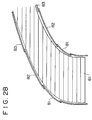
- overlapping portions is created to form jointing portions between handrail portions 81, 82 and 83 as shown in Fig. 28.
- this moving handrail since there are overlapping regions as jointing portions between adjacent handrail portions as stated above, the ends of the handrail portions may disturb the proceeding of passengers in some cases, depending on the proceeding direction of the passenger, thereby jeopardizing the passenger. Further, deviation of the proceeding direction of the passenger from the moving direction of the handrail makes the passengers feel uneasy.
- the present invention is to eliminate the aforementioned defects and drawbacks in the conventional system by constructing a new system as follows.
- An object of the present invention is to provide a handrail mechanism for a speed variable moving sidewalk in which overlaps in jointing portions are left out so as to avert potential dangers and which presents a more conformable riding to the passengers by arranging moving handrails in such a manner that the advancing directions of the moving handrails correspond to the advancing direction of the passenger's body.
- a second aspect of the present invention is to achieve the above object, and relates to the following features as to a handrail mechanism for a speed variable moving sidewalk wherein a large number of the treadboards are circularly moved along endless rails composed of vertical portions, and upper and lower portions each being made up of combination of a substantially straight portion and curved portions on a horizontal plane, and are transversely slid relative to one another in upper and lower portion for acceleration or retardation thereof.
- each moving handrail portion is driven independently of the others at a speed close to the moving speed of nearby treadboards, the passengers can move on the sidewalk while holding the moving handrail. Further, an end of the moving handrail portion on the passenger side at the conventional overlapping portion would be obstructing to the passenger. This problem attributable to the overlapping portion, however, does not occur because, in the configuration of the present invention, no overlapping portion exists between neighboring moving handrail portions. Therefore, the passenger's body and his or her hand are to move in the same direction at all time. Moreover the guiding plates provided at jointing portions make it possible to transfer the passenger's hand from one moving handrail portion to the next moving handrail portion in safety.
- each handrail portion Since the surface of each handrail portion is provided with comb-like grooves which mate with the guiding plate, this configuration prevents the passenger's hand from being accidentally nipped by the clearance between the handrail and the guiding plate and makes it possible for the passenger to transfer his or her hand from one moving rail portion to the guiding plate in safety.
- an electric indicator such as a winker etc.
- a sound/voice indicator and/or an air-blowing device is provided for informing passengers of the existence of a guiding plate, it is possible for the passenger to transfer his or her hand from one moving rail portion to the guiding plate in safety.
- the guiding plate is composed of an endless belt which moves in the same direction at the same speed as the adjoining handrail portions move, it is possible for the passenger to easily transfer his or her hand from one moving rail portion to the guiding plate.
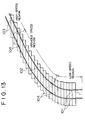
- Fig. 13 is a plan view showing a handrail system for a speed variable moving sidewalk in accordance with an embodiment of the present invention.
- the figure shows only a half of the whole system since the system has a point-symmetric structure.
- Fig. 14 is a sectional view showing a typical part of the same sidewalk.
- moving handrail portions 101, 102 and 103 independently serve for the low-speed range, the accelerating range and the high-speed range, respectively, and run circularly at speeds close to the speeds of treadboards in respective regions.
- Guiding plates 104 are provided at the joints between the moving handrail portions 102 and 103. Each guiding plate 104 is fixed or integrated on the wainscot panel (the inside panel).
- Fig. 15 ia side view showing a detail of a joint portion between the handrail portions shown in Fig. 13.
- Fig. 16 is a plan view of the same joint portion, viewed from the top (from Y-direction in Fig. 15).
- Fig. 17 is an enlarged view of a portion indicated by Z in Fig. 16.
- each of the moving handrail portions 101, 102 and 103 has a comb-like pattern on the surface thereof similar to that provided on treadboards and mates with the guiding plate 104 in the joint portion between the moving handrail portions shown in Fig. 15.
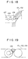
- Fig. 18 is a perspective view showing the top face of the guiding plate.
- the guiding plate 104 has claws at the ends thereof which mate with the moving handrail portion 101, 102 or 103.
- the surface of the guiding plate must be well polished for eased sliding, but in order to assure further smoothness, balls 107 or rollers may be provided on the surface of the guiding plate as illustrated in Fig. 18, whereby the passenger's hand can transfer further smoothly to the next handrail portions 102 or 103 even when his or her hand is propped on the guiding plate.
- an air blow hole 108 is provided as illustrated in the guiding plate 104 or in the vicinity thereof so as to blow air against the passenger's hand approaching in order to attract his or her attention.
- an electric indicator or sound or voice announce etc. may be used solely or in combination so that it is possible to give a further sense of security to the passenger.
- Fig. 19 is a side view of another configuration of a guiding plate at the joint portion.
- a small moving handrail or flat belt 109 is provided and driven at a speed close to those of the moving handrails before and after.
- the safety for passengers can be improved in the following aspects as compared to the prior art mechanism in which handrail portions are overlapped with each other at their joint portions.
Landscapes
- Escalators And Moving Walkways (AREA)
Abstract
Description
Claims (5)
- A handrail mechanism for a speed variable moving sidewalk wherein a large number of treadboards (1) are circularly moved along endless rails composed of vertical portions, and upper and lower portions each being made up of combination of a linear portion and curved portions within a horizontal plane and are transversely slid relative to one another in the upper and lower portions for acceleration or retardation thereof,with a total length of said moving sidewalk being divided into plural portions, characterized byan independently moving handrail (101, 102, 103) arranged for each of said divided plural portions of said sidewalk while said moving handrails (101, 102, 103) are arranged without overlapping with one another, each of said moving handrails (101, 102, 103) adapted for being driven at a speed close to a driving speed of nearby treadboards (1); anda plurality of guiding plates (104) being disposed at jointing portions between adjoining moving handrails (101, 102, 103) to thereby guide passenger's hands from one moving handrail (101, 102, 103) to a next moving handrail (101, 102, 103).
- A handrail mechanism for a speed variable moving sidewalk according to Claim 1 wherein said moving handrails (101, 102, 103) are provided on a surface thereof with comb-like grooves so as to be smoothly connected to said guiding plate (104).
- A handrail mechanism for a speed variable moving sidewalk according to Claim 1 wherein said guiding plate (104) has freely rolling balls (107) or rollers arranged thereon.
- A handrail mechanism for a speed variable moving sidewalk according to Claim 1 wherein, in order to inform passengers of existence of a guiding plate (104), at least one of an electric indicator, a sound/voice indicator, and an air-blowing device (108) is provided on an upper face of or in the vicinity of said guiding plate (104).
- A handrail mechanism for a speed variable moving sidewalk according to Claim 1 wherein said guiding plate (104) is composed of an endless belt (109) and an upper face of said endless belt (109) is adapted to be driven in the same direction at an approximately identical speed as upper parts of the adjoining moving handrails (101, 102, 103) move.
Applications Claiming Priority (7)
| Application Number | Priority Date | Filing Date | Title |
|---|---|---|---|
| JP246874/93 | 1993-10-01 | ||
| JP24687493 | 1993-10-01 | ||
| JP24687493A JP3382679B2 (en) | 1993-10-01 | 1993-10-01 | Acceleration / deceleration type moving sidewalk |
| JP251613/93 | 1993-10-07 | ||
| JP5251613A JPH07101662A (en) | 1993-10-07 | 1993-10-07 | Handrail for acceleration-deceleration type moving footpath |
| JP25161393 | 1993-10-07 | ||
| EP94115238A EP0646538B1 (en) | 1993-10-01 | 1994-09-28 | A speed variable moving sidewalk |
Related Parent Applications (1)
| Application Number | Title | Priority Date | Filing Date |
|---|---|---|---|
| EP94115238A Division EP0646538B1 (en) | 1993-10-01 | 1994-09-28 | A speed variable moving sidewalk |
Publications (2)
| Publication Number | Publication Date |
|---|---|
| EP0837026A1 true EP0837026A1 (en) | 1998-04-22 |
| EP0837026B1 EP0837026B1 (en) | 2002-01-02 |
Family
ID=26537949
Family Applications (2)
| Application Number | Title | Priority Date | Filing Date |
|---|---|---|---|
| EP94115238A Expired - Lifetime EP0646538B1 (en) | 1993-10-01 | 1994-09-28 | A speed variable moving sidewalk |
| EP97122730A Expired - Lifetime EP0837026B1 (en) | 1993-10-01 | 1994-09-28 | A handrail mechanism for a variable speed moving sidewalk |
Family Applications Before (1)
| Application Number | Title | Priority Date | Filing Date |
|---|---|---|---|
| EP94115238A Expired - Lifetime EP0646538B1 (en) | 1993-10-01 | 1994-09-28 | A speed variable moving sidewalk |
Country Status (4)
| Country | Link |
|---|---|
| US (1) | US5571254A (en) |
| EP (2) | EP0646538B1 (en) |
| KR (1) | KR0147083B1 (en) |
| DE (2) | DE69429678T2 (en) |
Cited By (3)
| Publication number | Priority date | Publication date | Assignee | Title |
|---|---|---|---|---|
| US6602331B2 (en) | 2001-10-05 | 2003-08-05 | Thyssen Norte, S.A. | Handrail for variable speed moving walkway |
| EP3549897A1 (en) | 2018-04-04 | 2019-10-09 | ThyssenKrupp Elevator Innovation Center S.A. | A handrail safety device for a moving walkway |
| EP3549898A1 (en) | 2018-04-04 | 2019-10-09 | Thyssenkrupp Elevator Innovation Center, S.A. | A moving walking system and a handrail bridging system |
Families Citing this family (25)
| Publication number | Priority date | Publication date | Assignee | Title |
|---|---|---|---|---|
| JPH09126953A (en) * | 1995-11-01 | 1997-05-16 | Bridgestone Corp | Flat plate circulation device and force measuring device |
| JPH1087248A (en) * | 1996-09-20 | 1998-04-07 | Mitsubishi Heavy Ind Ltd | Variable speed conveyer |
| DE29615912U1 (en) * | 1996-09-12 | 1996-10-31 | Woodway AG, Schönenberg | Treadmill |
| EP0931753A1 (en) * | 1998-01-23 | 1999-07-28 | Nkk Corporation | Variable-speed passenger conveyor and handrail device therefor |
| JP3505391B2 (en) * | 1998-06-08 | 2004-03-08 | 株式会社日立製作所 | Variable speed passenger conveyor |
| US6138816A (en) * | 1998-06-19 | 2000-10-31 | Nkk Corporation | Variable-speed passenger conveyer and handrail device thereof |
| JP2000169066A (en) * | 1998-12-03 | 2000-06-20 | Ishikawajima Transport Machinery Co Ltd | Variable speed sidewalk |
| ES2179720B1 (en) | 1999-11-19 | 2004-03-16 | Thyssen Norte S A | ACCELERATION HALL. |
| FI20040304A0 (en) * | 2004-02-26 | 2004-02-26 | Kone Corp | Walkway, ramp or staircase |
| US7595976B2 (en) * | 2004-10-21 | 2009-09-29 | Mitsubishi Denki Kabushiki Kaisha | Outdoor apparatus |
| CN100526194C (en) * | 2005-06-07 | 2009-08-12 | 因温特奥股份公司 | Wheel for driving a flexible handrail |
| ES2281305B1 (en) | 2006-12-28 | 2008-06-01 | Thyssenkrupp Norte, S.A. | SECURITY DEVICE FOR TRANSPORT SYSTEMS. |
| ES2289955B1 (en) * | 2006-12-29 | 2009-05-05 | Thyssenkrupp Norte, S.A. | TRANSPORTATION SYSTEM FOR PASSENGER / GOODS DISPLACEMENT. |
| US10183191B2 (en) * | 2009-11-02 | 2019-01-22 | Speedfit LLC | Leg-powered treadmill |
| NZ608668A (en) * | 2010-08-27 | 2014-10-31 | Dematic Corp | Positive displacement sorter |
| ES2369980B1 (en) * | 2011-07-29 | 2012-07-24 | Thyssenkrupp Elevator Innovation Center, S.A. | MOBILE CORRIDATED OPERATION SYSTEM. |
| JP5107485B2 (en) * | 2012-01-19 | 2012-12-26 | 勝哉 寺本 | Acceleration / deceleration handrail drive device |
| ES2726905T3 (en) * | 2014-12-12 | 2019-10-10 | Technogym Spa | Manual treadmill |
| DE102015113435A1 (en) * | 2015-08-14 | 2017-02-16 | Khs Gmbh | Transport device and transport method with such a transport device |
| CN106276556A (en) * | 2016-08-08 | 2017-01-04 | 熊涛 | Gradual speed carrying Transfer pipe |
| CN107490476A (en) * | 2017-09-30 | 2017-12-19 | 苏州奔机电有限公司 | A kind of walkway steps static test frock |
| EP3470360A1 (en) | 2017-10-10 | 2019-04-17 | Thyssenkrupp Elevator Innovation Center, S.A. | Split handrail for passenger moving walking systems |
| EP3736242A1 (en) * | 2019-05-06 | 2020-11-11 | thyssenkrupp Elevator Innovation Center, S.A. | Anti-entrapment safety system |
| CN110667712B (en) * | 2019-10-29 | 2025-02-18 | 咸宁职业技术学院 | Automatic road vehicle steering, branching and merging devices |
| CN110921476A (en) * | 2019-12-17 | 2020-03-27 | 郄树才 | Combinable moving sidewalk |
Citations (3)
| Publication number | Priority date | Publication date | Assignee | Title |
|---|---|---|---|---|
| FR2060830A5 (en) * | 1970-09-02 | 1971-06-18 | Bocquet Lucien | |
| US4232776A (en) * | 1978-01-05 | 1980-11-11 | Dean Research Corporation | Accelerating walkway |
| EP0576353A1 (en) * | 1992-06-24 | 1993-12-29 | Pierre Patin | Variable speed transportation device, in particular for accelerated moving walkways |
Family Cites Families (10)
| Publication number | Priority date | Publication date | Assignee | Title |
|---|---|---|---|---|
| US2936873A (en) * | 1956-06-21 | 1960-05-17 | Sol H Seidman | Load transfer system |
| US3052337A (en) * | 1960-11-28 | 1962-09-04 | Sr John W Force | Safety landing for moving sidewalk |
| US3859924A (en) * | 1970-03-24 | 1975-01-14 | Nat Res Dev | Transport systems |
| CH529646A (en) * | 1970-07-17 | 1972-10-31 | Dunlop Holdings Ltd | Conveyor device |
| GB1443318A (en) * | 1973-01-10 | 1976-07-21 | Hamy N | Transport systems |
| GB1455586A (en) * | 1973-03-20 | 1976-11-17 | Dunlop Ltd | Conveyor handrail |
| JPS5342957B2 (en) * | 1973-03-23 | 1978-11-15 | ||
| EP0352968B1 (en) * | 1988-07-25 | 1994-10-26 | Loderway Pty. Limited | A moving walkway |
| JPH0747459B2 (en) * | 1988-11-09 | 1995-05-24 | 株式会社日立製作所 | Display device for passenger conveyor, display body used therefor, and method for assembling display device |
| JPH0818780B2 (en) * | 1989-08-25 | 1996-02-28 | 株式会社日立製作所 | Passenger conveyor |
-
1994
- 1994-09-28 EP EP94115238A patent/EP0646538B1/en not_active Expired - Lifetime
- 1994-09-28 KR KR1019940024565A patent/KR0147083B1/en not_active Expired - Fee Related
- 1994-09-28 DE DE69429678T patent/DE69429678T2/en not_active Expired - Fee Related
- 1994-09-28 DE DE69417136T patent/DE69417136T2/en not_active Expired - Fee Related
- 1994-09-28 EP EP97122730A patent/EP0837026B1/en not_active Expired - Lifetime
- 1994-09-30 US US08/316,571 patent/US5571254A/en not_active Expired - Fee Related
Patent Citations (3)
| Publication number | Priority date | Publication date | Assignee | Title |
|---|---|---|---|---|
| FR2060830A5 (en) * | 1970-09-02 | 1971-06-18 | Bocquet Lucien | |
| US4232776A (en) * | 1978-01-05 | 1980-11-11 | Dean Research Corporation | Accelerating walkway |
| EP0576353A1 (en) * | 1992-06-24 | 1993-12-29 | Pierre Patin | Variable speed transportation device, in particular for accelerated moving walkways |
Cited By (3)
| Publication number | Priority date | Publication date | Assignee | Title |
|---|---|---|---|---|
| US6602331B2 (en) | 2001-10-05 | 2003-08-05 | Thyssen Norte, S.A. | Handrail for variable speed moving walkway |
| EP3549897A1 (en) | 2018-04-04 | 2019-10-09 | ThyssenKrupp Elevator Innovation Center S.A. | A handrail safety device for a moving walkway |
| EP3549898A1 (en) | 2018-04-04 | 2019-10-09 | Thyssenkrupp Elevator Innovation Center, S.A. | A moving walking system and a handrail bridging system |
Also Published As
| Publication number | Publication date |
|---|---|
| KR0147083B1 (en) | 1998-08-17 |
| US5571254A (en) | 1996-11-05 |
| EP0646538A3 (en) | 1995-08-09 |
| DE69429678T2 (en) | 2002-08-14 |
| DE69417136T2 (en) | 1999-08-26 |
| DE69417136D1 (en) | 1999-04-22 |
| DE69429678D1 (en) | 2002-02-28 |
| KR950011313A (en) | 1995-05-15 |
| EP0646538B1 (en) | 1999-03-17 |
| EP0837026B1 (en) | 2002-01-02 |
| EP0646538A2 (en) | 1995-04-05 |
Similar Documents
| Publication | Publication Date | Title |
|---|---|---|
| EP0837026B1 (en) | A handrail mechanism for a variable speed moving sidewalk | |
| US4662502A (en) | Curved escalator | |
| US5697486A (en) | Device for the guidance of an endless belt for escalators or moving walkways | |
| JPH10203766A (en) | Conveyor belt for passenger | |
| KR20020006025A (en) | Escalator | |
| JP4236846B2 (en) | Inclined part high-speed escalator | |
| EP0424209B2 (en) | Escalator with verical planar step risers and constant horizontal velocity | |
| EP1452476B1 (en) | High speed escalator for slope | |
| JPH0357024B2 (en) | ||
| KR100527218B1 (en) | Sloped part high-speed escalator | |
| KR20030064261A (en) | Escalator with high speed inclined section | |
| EP1468951A1 (en) | Sloped part high-speed escalator | |
| JP3395607B2 (en) | Passenger conveyor railing equipment | |
| JP3589103B2 (en) | Moving sidewalk handrail | |
| WO2003062120A1 (en) | Sloped part high-speed escalator | |
| JPH11301957A (en) | Passenger conveyor railing equipment | |
| JPH11246160A (en) | Variable speed passenger conveyor railing device | |
| JP2005022800A (en) | Multi-speed man conveyor | |
| JPH01150688A (en) | moving road | |
| JPS5878880U (en) | escalator | |
| JPH0532375U (en) | A moving walkway with an entrance and exit | |
| JPH0772073B2 (en) | Passenger conveyor | |
| JPS6127887A (en) | Follower chain sprocket device for curve type passenger conveyor | |
| JPH0640689A (en) | Moving handrails for variable speed passenger conveyors | |
| JPH08225281A (en) | Handrail device for variable-speed moving footpath |
Legal Events
| Date | Code | Title | Description |
|---|---|---|---|
| PUAI | Public reference made under article 153(3) epc to a published international application that has entered the european phase |
Free format text: ORIGINAL CODE: 0009012 |
|
| AC | Divisional application: reference to earlier application |
Ref document number: 646538 Country of ref document: EP |
|
| AK | Designated contracting states |
Kind code of ref document: A1 Designated state(s): DE FR GB IT |
|
| 17P | Request for examination filed |
Effective date: 19980506 |
|
| 17Q | First examination report despatched |
Effective date: 19990408 |
|
| GRAG | Despatch of communication of intention to grant |
Free format text: ORIGINAL CODE: EPIDOS AGRA |
|
| DAX | Request for extension of the european patent (deleted) | ||
| GRAG | Despatch of communication of intention to grant |
Free format text: ORIGINAL CODE: EPIDOS AGRA |
|
| GRAH | Despatch of communication of intention to grant a patent |
Free format text: ORIGINAL CODE: EPIDOS IGRA |
|
| GRAH | Despatch of communication of intention to grant a patent |
Free format text: ORIGINAL CODE: EPIDOS IGRA |
|
| GRAA | (expected) grant |
Free format text: ORIGINAL CODE: 0009210 |
|
| REG | Reference to a national code |
Ref country code: GB Ref legal event code: IF02 |
|
| AC | Divisional application: reference to earlier application |
Ref document number: 646538 Country of ref document: EP |
|
| AK | Designated contracting states |
Kind code of ref document: B1 Designated state(s): DE FR GB IT |
|
| REF | Corresponds to: |
Ref document number: 69429678 Country of ref document: DE Date of ref document: 20020228 |
|
| ET | Fr: translation filed | ||
| PLBE | No opposition filed within time limit |
Free format text: ORIGINAL CODE: 0009261 |
|
| STAA | Information on the status of an ep patent application or granted ep patent |
Free format text: STATUS: NO OPPOSITION FILED WITHIN TIME LIMIT |
|
| 26N | No opposition filed | ||
| REG | Reference to a national code |
Ref country code: GB Ref legal event code: 746 Effective date: 20040615 |
|
| REG | Reference to a national code |
Ref country code: FR Ref legal event code: D6 |
|
| PGFP | Annual fee paid to national office [announced via postgrant information from national office to epo] |
Ref country code: FR Payment date: 20040908 Year of fee payment: 11 |
|
| PGFP | Annual fee paid to national office [announced via postgrant information from national office to epo] |
Ref country code: GB Payment date: 20040922 Year of fee payment: 11 |
|
| PGFP | Annual fee paid to national office [announced via postgrant information from national office to epo] |
Ref country code: DE Payment date: 20040923 Year of fee payment: 11 |
|
| PG25 | Lapsed in a contracting state [announced via postgrant information from national office to epo] |
Ref country code: IT Free format text: LAPSE BECAUSE OF NON-PAYMENT OF DUE FEES;WARNING: LAPSES OF ITALIAN PATENTS WITH EFFECTIVE DATE BEFORE 2007 MAY HAVE OCCURRED AT ANY TIME BEFORE 2007. THE CORRECT EFFECTIVE DATE MAY BE DIFFERENT FROM THE ONE RECORDED. Effective date: 20050928 Ref country code: GB Free format text: LAPSE BECAUSE OF NON-PAYMENT OF DUE FEES Effective date: 20050928 |
|
| PG25 | Lapsed in a contracting state [announced via postgrant information from national office to epo] |
Ref country code: DE Free format text: LAPSE BECAUSE OF NON-PAYMENT OF DUE FEES Effective date: 20060401 |
|
| GBPC | Gb: european patent ceased through non-payment of renewal fee |
Effective date: 20050928 |
|
| PG25 | Lapsed in a contracting state [announced via postgrant information from national office to epo] |
Ref country code: FR Free format text: LAPSE BECAUSE OF NON-PAYMENT OF DUE FEES Effective date: 20060531 |
|
| REG | Reference to a national code |
Ref country code: FR Ref legal event code: ST Effective date: 20060531 |