EP0836819A2 - Height-adjustable chair arm assembly - Google Patents
Height-adjustable chair arm assembly Download PDFInfo
- Publication number
- EP0836819A2 EP0836819A2 EP97308230A EP97308230A EP0836819A2 EP 0836819 A2 EP0836819 A2 EP 0836819A2 EP 97308230 A EP97308230 A EP 97308230A EP 97308230 A EP97308230 A EP 97308230A EP 0836819 A2 EP0836819 A2 EP 0836819A2
- Authority
- EP
- European Patent Office
- Prior art keywords
- gear
- slide tube
- arm
- lock member
- support segment
- Prior art date
- Legal status (The legal status is an assumption and is not a legal conclusion. Google has not performed a legal analysis and makes no representation as to the accuracy of the status listed.)
- Withdrawn
Links
Images


Classifications
-
- A—HUMAN NECESSITIES
- A47—FURNITURE; DOMESTIC ARTICLES OR APPLIANCES; COFFEE MILLS; SPICE MILLS; SUCTION CLEANERS IN GENERAL
- A47C—CHAIRS; SOFAS; BEDS
- A47C1/00—Chairs adapted for special purposes
- A47C1/02—Reclining or easy chairs
- A47C1/022—Reclining or easy chairs having independently-adjustable supporting parts
- A47C1/03—Reclining or easy chairs having independently-adjustable supporting parts the parts being arm-rests
- A47C1/0303—Reclining or easy chairs having independently-adjustable supporting parts the parts being arm-rests adjustable rectilinearly in vertical direction
- A47C1/0305—Reclining or easy chairs having independently-adjustable supporting parts the parts being arm-rests adjustable rectilinearly in vertical direction by peg-and-notch or pawl-and-ratchet mechanism
-
- A—HUMAN NECESSITIES
- A47—FURNITURE; DOMESTIC ARTICLES OR APPLIANCES; COFFEE MILLS; SPICE MILLS; SUCTION CLEANERS IN GENERAL
- A47C—CHAIRS; SOFAS; BEDS
- A47C1/00—Chairs adapted for special purposes
- A47C1/02—Reclining or easy chairs
- A47C1/022—Reclining or easy chairs having independently-adjustable supporting parts
- A47C1/03—Reclining or easy chairs having independently-adjustable supporting parts the parts being arm-rests
Definitions
- the invention relates to chairs with adjustable arms and, more particularly, to an armrest which can be conveniently vertically adjusted with respect to the chair seat.
- Chairs designed for use particularly in office environments and the like are being increasingly provided with adjustment features so as to improve the ergonomics of the chair, particularly in those situations where the chair is used for long periods of time, such as when an occupant is working at a computer terminal, to provide improved comfort and healthful support of the occupant's body.
- One of the areas which has been addressed to improve such comfort relates to the chair arms, and same known chairs have provided arms having position adjustability, particularly with respect to the ability to vary the armrest height relative to the seat.
- the known chairs which possess height-adjustable chair arms typically employ vertically telescopic supports and a cooperating releasable latch arrangement for permitting height adjustment.
- Most knownarrangements have disadvantages, either from a manufacturing or structural viewpoint, or from an operational viewpoint.
- many of the structures are undesirably complex, and/or do not provide for approximately continuous height adjustment (in contrast to discrete height adjustment at a small number of widely spaced-apart discrete positions) and/or have a less secure locking arrangement that may allow disengagement of the locking parts which may cause the accidental lowering of the armrest relative to the chair seat and/or the overall support arrangement and cooperating latch mechanism is such as to make release of the latch and adjustment of arm height difficult or inconvenient, particularly to an occupant seated in the chair.
- the improved height-adjustable chair arm assembly of this invention provides an improved locking mechanism which extends through the armrest and into the arm upright so as to permit easy and efficient unlocking and height adjustment if desired, with the occupant in a seated position being able to easily release and maintain the locking mechanism in a releasing position, and with the occupant having the feel of approximately continuous height adjustment of the arm assembly, while at the same time permitting the occupant to easily raise or lower the arm while seated, and then permit the locking mechanism to re-engage.
- the present invention comprises a chair having height-adjustable arm assemblies respectively mounted adjacent opposite sides of a seat.
- Each arm assembly includes a horizontally elongate armrest which is connected to an upper end of an arm upright.
- the arm upright includes a vertically oriented support segment which has a guide bore defined therein.
- the armrest includes a vertically elongate slide tube and a horizontally elongate arm element.
- the arm element is connected to an upper end of the slide tube.
- a lower end of the slide tube is movably mounted within the guide bore.
- a lock arrangement functions to permit the slide tube to be positioned relative to the support segment at any one of a plurality of height positions.
- the lock arrangement includes a cartridge assembly that has a gear which is rotatably supported and carried by the slide tube.
- the gear has a plurality of gear teeth which engage with a series of vertically spaced notches (i.e. a gear rack) defined within the support segment.
- a lock releasing mechanism functions to displace a lock member between a locking position and a releasing position.
- the lock releasing mechanism includes an actuator lever and an actuator rod. The actuator lever is supported on the arm element and the actuator rod extends into the support element and mounts the lock member thereon.
- the lock member has a plurality of locking teeth which engage the gear when the lock member is positioned in the locking position.
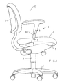
- FIG 1 diagrammatically illustrates a chair 2, often referred to as an office-type chair.
- This chair employs a center pedestal 3 which projects upwardly from a wheeled base 4.
- a suitable seat assembly is mounted on an upper end of the center pedestal 3.
- the seat assembly includes a chair seat 6 and a chair control or seat frame 5.
- the chair control 5 supports the chair seat 6 and is mounted thereto.
- a chair back 7 projects upwardly from a location above the rear edge of the chair seat 6.
- the chair 2 is provided with a pair of height-adjustable arm assemblies 8 mounted thereon, namely right and left assemblies which are respectively disposed adjacent the right and left sides of the seat 6 so as to project upwardly therefrom to hence permit the chair occupant to be seated therebetween.
- the right and left chair arm assemblies 8 are substantially identical except for being mirror images of one another, and only the right side assembly is visible in Figure 1.
- the right side height-adjustable arm assembly 8 includes an arm upright 10 which is fixed to and projects upwardly from adjacent the seat 6.
- the arm upright 10 in the illustrated embodiment is generally L-shaped and includes a base leg 10B which is fixed to the seat frame 5, and also includes a vertically elongate and upwardly cantilevered leg or support segment 10A.
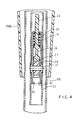
- the support segment 10A has an elongate plastic sleeve 12 fixed vertically therein.
- the sleeve 12 is constructed of two parts which effectively snap together.
- the sleeve 12 defines a guide bore 13 which extends through the sleeve.
- the sleeve 12 further defines interiorly thereof a gear rack 14 which has a plurality of uniformly vertically spaced notches as shown in Figure 3.
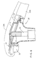
- the arm assembly 8 further includes an armrest 28 having an upper portion or arm cap 28A for supporting an occupant's arm thereon and a lower cover portion 28B extending downwardly from the upper portion.
- the armrest 28 also includes an arm element 21 having a slide tube 22 fixed thereto and projecting downwardly therefrom.
- the tube 22, in the illustrated embodiment, is of rectangular cross-section and is slidably supported within the guide bore 13 of the sleeve 12.
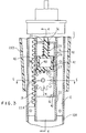
- the arm assembly 8 additionally includes a compact cartridge assembly 15 which is secured interiorly of the tube 22.
- the cartridge assembly 15 includes a generally channel-shaped housing 16 which is fixed within the tube 22.
- the tube 22 has a window or aperture 38 defined in a vertical side wall 22A thereof as shown in Figure 3, which window 38 communicates with the interior of the housing 16 through an open side thereof.
- a gear 24 is rotatably supported within the housing 16 by a pin 17 which extends transversely between and is supported on opposite side walls of the housing 16.
- the gear 24 is supported in the housing 16 such that a plurality of teeth on one side of the gear 24 project through the open side of the housing and extend through the aperture 38 so as to engage the plurality of vertically spaced notches of the gear rack 14 as shown in Figure 3.
- the housing 16 further has an opening 36 defined within a top wall thereof.
- An elongate actuator rod 25 projects downwardly through the tube 22 and the housing opening 36 and has a lock member 26 secured to the lower end thereof.
- the lock member 26 includes a plurality of downwardly projecting locking teeth 27 which engage the upper toothed portion of the gear 24.
- the locking teeth 27 are configured to be generally rectangularly shaped as shown in Figures 3 and 7.
- the locking teeth 27 protrude downwardly from a substantially planar bottom portion 34 of the lock member 26.
- Figure 7 depicts a side elevational view of the lock member 26 which shows the planar bottom portion of the lock member defining a line L from which the locking teeth 27 protrude.
- the locking teeth 27 are configured to be generally rectangularly shaped and have generally parallel side surfaces which protrude substantially perpendicularly from a substantially planar wall portion of the lock member 26, the locking teeth 27 and the gear 24 cooperate so as to provide for a more positive locking relationship therebetween which reduces the likelihood of accidental disengagement between the locking teeth 27 and the gear 24.
- the lock member 26 is vertically slidably confined within the cartridge housing 16 by being slidably engaged and positioned between the bight or base wall of the channel-shaped housing 16 and the wall 22A of the tube 22 as shown in Figure 3.
- a spring 29 coacts between the top wall of housing 16 and the locking member 26 for movably biasing the locking teeth 27 downwardly in perpendicular relation relative to the rotational axis of the gear 24 into a position of meshed engagement with gear 24 as illustrated in Figure 3.
- the lock member 26 is thus confined for movement in a direction which is substantially perpendicular to the rotational axis of the gear 24.
- the engaged or meshed relation between the locking teeth 27 and the teeth of gear 24 also occurs on or is substantially centered along a radial line which intersects the gear axis and which is substantially parallel with the movement direction of the lock member 26.
- the actuator rod 25 has its upper end coupled to an actuator lever 31.
- a first end of the actuator lever 31 is urged downwardly against the arm element 21 at a pivot point 30.
- a second end of the actuator lever 31 extends through an opening 32 defined in the arm element 21.
- a finger-engaging pad or button 33 Secured to the second end of the actuator lever 31 is a finger-engaging pad or button 33.
- the pad 33 is located adjacent to but under a forward end of the armrest 28 for easy engagement by an occupant's fingers.
Landscapes
- Health & Medical Sciences (AREA)
- Dentistry (AREA)
- General Health & Medical Sciences (AREA)
- Seats For Vehicles (AREA)
- Chairs For Special Purposes, Such As Reclining Chairs (AREA)
- Chair Legs, Seat Parts, And Backrests (AREA)
Abstract

Description
Claims (20)
- In a chair having a seat assembly, a back projecting upwardly from a location adjacent a rear edge of the seat assembly, and a pair of height-adjustable arm assemblies mounted on and disposed adjacent opposite sides of said seat assembly and projecting upwardly in cantilevered relation therefrom, the improvement wherein each arm assembly comprises:an arm upright fixed to said seat assembly and including a vertically elongate support segment disposed on one side of said seat assembly, said support segment defining therein a vertically elongate guide bore which is open at an upper end thereof;an armrest having a vertically elongate slide tube lengthwise movably supported within said guide bore and projecting upwardly therefrom and terminating at an upper end part which is disposed at an elevation spaced upwardly above said seat assembly, said armrest further having a horizontally elongate arm element mounted on the upper end part of said slide tube and projecting horizontally therefrom;a releasable lock arrangement coacting between said support segment and said slide tube for permitting said slide tube to be stationarily fixedly positioned relative to said support segment at any one of a plurality of selectable height positions, said lock arrangement including a gear which is rotatably supported and carried in said slide tube, said gear having a plurality of gear teeth which engage with a series of vertically spaced notches which are defined within said support segment; anda lock releasing mechanism extending from said armrest into said support segment and including a lock member movable between a locking position and a releasing position, said lock releasing mechanism further including an actuator arm extending lengthwise of and movably supported on said arm element and terminating in a manually-engagable button part disposed at an underside of said arm element adjacent an end portion thereof, and an actuator rod extending interiorly and lengthwise of said support segment and having an upper end cooperating with said actuator arm and a lower end coupled to the lock member, said lock member having a locking tooth which engages said gear when the lock member is positioned in the locking position.
- A chair according to claim 1, wherein said lock member has a substantially planar bottom portion having a plurality of locking teeth extend downwardly therefrom.
- A chair according to claim 2, wherein said locking teeth are substantially rectangularly shaped.
- A chair according to Claim 1, wherein said lock arrangement includes a housing in which said gear is rotatably supported, said housing being fixedly positioned within said slide tube.
- A chair according to Claim 4, wherein said lock arrangement includes a pin retained within said housing, said gear being supported by said pins for rotation about the axis thereof.
- A chair according to Claim 4, wherein said housing has an opening defined within a top wall thereof, and said actuator rod extends through said opening of said top wall.
- A chair according to Claim 6, wherein said lock arrangement includes a spring which is positioned around said actuator rod at a location between said lock member and said top wall of said housing.
- A chair according to Claim 6, wherein said housing and said slide tube have openings defined in vertical side walls thereof, and said gear is rotatably mounted within said housing such that gear teeth thereof extend through said apertures so as to engage the series of vertically spaced notches which are defined within said support segment.
- A chair according to Claim 4, wherein said lock member is fixed to a lower end of said actuator rod and is vertically slidably supported in said housing at a position directly above said gear.
- A chair according to Claim 1, wherein said actuator arm includes a first end which is biased against said arm element at a pivot point, and a second end which ends through an opening defined within said arm element.
- A chair according to Claim 10, wherein said upper end of said actuator rod is attached to said actuator lever at a location between said first and second ends of said actuator arm.
- A height-adjustable arm assembly for a chair, comprising:an arm upright including a vertically elongate support segment, said support segment defining therein a vertically elongate guide bore which is open at an upper end thereof;an armrest having an elongate slide tube lengthwise movably supported within said guide bore and projecting upwardly therefrom and terminating at an upper end part, said armrest further having a horizontally elongate arm element mounted on the upper end part of said slide tube and projecting horizontally therefrom;a releasable lock arrangement coacting between said support segment and said slide tube for permitting said slide tube to be stationarily fixedly positioned relative to said support segment at any one of a plurality of selectable height positions, said lock arrangement including a gear which is rotatably supported and carried by said slide tube, said gear having a plurality of gear teeth which engage with a series of vertically spaced notches which are defined within said support segment, and a movable lock member positioned adjacent said gear within said slide tube, said lock member having a plurality of locking teeth which engage said gear when the lock member is positioned in the locking position; anda lock releasing mechanism extending from said armrest into said support segment for displacing the lock member between a locking position and a releasing position, said lock releasing mechanism including an actuator arm extending lengthwise of and movably supported on said arm element and terminating in a manually-engagable button part disposed at an underside of said arm element adjacent an end portion thereof, and an actuator rod extending interiorly and lengthwise of said support segment and having an upper end cooperating with said actuator arm and a lower end coupled to the lock member.
- A chair according to claim 12, wherein said lock member has a substantially planar bottom portion, and said plurality of locking teeth are substantially rectangularly shaped and extend downwardly from said planar bottom portion.
- A chair according to Claim 12, wherein said lock arrangement includes a housing and a pin, and said gear is rotatably supported by said pin within said housing for rotation about an axis which extends transversely relative to the lengthwise extent of said slide tube.
- A chair according to Claim 14, wherein said housing has an opening defined within a top wall thereof, and said actuator rod extends through said opening of said top wall, and said lock member is vertically slidably supported within said housing above said gear.
- A chair according to Claim 15, wherein said lock arrangement further includes a spring which is positioned around said actuator rod at a location between said lock member and said top wall of said housing.
- A chair according to Claim 15, wherein said slide tube and said housing have openings defined in vertical side walls thereof, and said gear is rotatably mounted within said housing such that the gear teeth thereof extend through said openings so as to engage the series of vertically spaced notches which are defined within said support segment.
- A chair according to Claim 12, wherein said actuator arm includes a first end which is biased against said arm element at a pivot point, and a second end which ends through an opening defined within said arm element, and said upper end of said actuator rod is attached to said actuator lever at a location between said first end and said second end of said actuator lever.
- A height-adjustable arm assembly for a chair, comprising:an arm upright including an elongate support segment, said support segment defining therein an elongate guide bore which is open at an upper end thereof;an armrest having an elongate slide tube and an arm element, said slide tube having a first end which is supported within said guide bore and a second end which is attached to said arm element;a releasable lock arrangement for permitting said slide tube to be stationarily positioned relative to said support segment at any one of a plurality of height positions, said lock arrangement including a gear which is rotatably supported and carried by said slide tube, said gear having a plurality of gear teeth which engage with a series of vertically spaced notches which are defined within said support segment, and a movable lock member positioned adjacent said gear; anda lock releasing mechanism for displacing said lock member between a locking position and a releasing position, said lock releasing mechanism including an actuator part supported adjacent said arm element and connected to an actuator rod extending into said support segment, said lock member being coupled to a lower end of said actuator rod and having one or more locking teeth which engage said gear when the lock member is positioned in the locking position.
- A chair according to claim 19, wherein said lock member has a substantially planar bottom portion, and each of said plurality of locking teeth are substantially rectangularly shaped and extend downwardly from said planar bottom portion.
Applications Claiming Priority (2)
| Application Number | Priority Date | Filing Date | Title |
|---|---|---|---|
| US731712 | 1996-10-17 | ||
| US08/731,712 US5829839A (en) | 1996-10-17 | 1996-10-17 | Height-adjustable chair arm assembly having gear-type adjusting mechanism |
Publications (2)
| Publication Number | Publication Date |
|---|---|
| EP0836819A2 true EP0836819A2 (en) | 1998-04-22 |
| EP0836819A3 EP0836819A3 (en) | 2000-03-01 |
Family
ID=24940664
Family Applications (1)
| Application Number | Title | Priority Date | Filing Date |
|---|---|---|---|
| EP97308230A Withdrawn EP0836819A3 (en) | 1996-10-17 | 1997-10-16 | Height-adjustable chair arm assembly |
Country Status (3)
| Country | Link |
|---|---|
| US (1) | US5829839A (en) |
| EP (1) | EP0836819A3 (en) |
| CA (1) | CA2218222A1 (en) |
Cited By (9)
| Publication number | Priority date | Publication date | Assignee | Title |
|---|---|---|---|---|
| WO1998055006A2 (en) | 1997-06-06 | 1998-12-10 | Haworth, Inc. | Height adjustable chair arm |
| US6802566B2 (en) | 2000-09-28 | 2004-10-12 | Formway Furniture Limited | Arm assembly for a chair |
| GB2435296A (en) * | 2006-02-20 | 2007-08-22 | Hoolin Res Co Ltd | Elevation adjustment structure for a display device |
| USD703988S1 (en) | 2013-06-07 | 2014-05-06 | Steelcase Inc. | Chair |
| USD703987S1 (en) | 2013-06-07 | 2014-05-06 | Steelcase Inc. | Chair |
| USD704487S1 (en) | 2013-06-07 | 2014-05-13 | Steelcase Inc. | Chair |
| USD706547S1 (en) | 2013-06-07 | 2014-06-10 | Steelcase Inc. | Chair |
| USD707976S1 (en) | 2013-06-07 | 2014-07-01 | Steelcase Inc. | Chair |
| USD721529S1 (en) | 2013-06-07 | 2015-01-27 | Steelcase Inc. | Handle apparatus |
Families Citing this family (15)
| Publication number | Priority date | Publication date | Assignee | Title |
|---|---|---|---|---|
| US6053579A (en) * | 1996-12-27 | 2000-04-25 | Haworth, Inc. | Height-Adjustable chair arm assembly having cam-type adjusting mechanism |
| US6394553B1 (en) | 2000-06-09 | 2002-05-28 | Knoll, Inc. | Adjustable armrest assembly with single adjustment lever |
| US7125077B2 (en) * | 2002-10-25 | 2006-10-24 | L&P Property Management Company | Seat bolster adjustment apparatus and method |
| US7011371B1 (en) * | 2004-11-29 | 2006-03-14 | Po-Chuan Tsai | Armrest assembly having a height adjustable function |
| US8235468B2 (en) | 2005-03-01 | 2012-08-07 | Haworth, Inc. | Arm assembly for a chair |
| CN102423202B (en) * | 2005-03-01 | 2015-07-29 | 霍沃思公司 | The arm assembly of chair |
| US7644991B2 (en) | 2006-06-02 | 2010-01-12 | Steelcase Inc. | Chair with folding armrest |
| US7434887B1 (en) * | 2008-01-03 | 2008-10-14 | Feng-Tien Hsien | Steplessly height-adjustable armrest structure |
| FR2958889A1 (en) * | 2010-04-20 | 2011-10-21 | Faurecia Sieges D Automobiles | DEVICE FOR ADJUSTING THE SEAT LENGTH FOR AN AUTOMOTIVE SEAT, AND SEAT COMPRISING SUCH A DEVICE |
| US9616785B2 (en) | 2014-01-09 | 2017-04-11 | PAC Seating Systems, Inc. | Infinitely vertically adjustable drop down armrest mechanism |
| US9974390B2 (en) * | 2016-08-18 | 2018-05-22 | Jenp-Jou Enterprise Co., Ltd. | Armrest |
| US10053173B1 (en) * | 2017-06-30 | 2018-08-21 | Back Forty Development, LLC | Height adjusting device |
| US9969448B1 (en) * | 2017-07-17 | 2018-05-15 | Kalloy Industrial Co., Ltd. | Bicycle seat adjustment device |
| CN209073846U (en) * | 2018-05-11 | 2019-07-09 | 杭州中泰实业集团有限公司 | A kind of Revolving chair tray that slider-crank mechanism is adjusted |
| FR3096619B1 (en) * | 2019-05-27 | 2024-08-02 | Faurecia Sieges Dautomobile | ARMREST SET FOR VEHICLE SEAT |
Citations (5)
| Publication number | Priority date | Publication date | Assignee | Title |
|---|---|---|---|---|
| FR1067160A (en) * | 1951-12-11 | 1954-06-14 | Franz Minet Mobelfabrik A G | Table |
| US3856252A (en) * | 1972-11-29 | 1974-12-24 | Aplications Ind Du Tube | Telescopic support for seats, tables and the like |
| US4951995A (en) * | 1989-10-10 | 1990-08-28 | Steelcase Inc. | Arm height adjustment mechanism for a chair |
| US5382079A (en) * | 1993-10-25 | 1995-01-17 | Chromcraft Revington, Inc. | Adjustable arm attachable to a chair body |
| US5439267A (en) * | 1993-05-28 | 1995-08-08 | Steelcase Inc. | Chair with adjustable arm assemblies |
Family Cites Families (10)
| Publication number | Priority date | Publication date | Assignee | Title |
|---|---|---|---|---|
| US208823A (en) * | 1878-10-08 | Improvement in piano-stools | ||
| US232790A (en) * | 1880-09-28 | Stool or chair | ||
| US504683A (en) * | 1893-09-05 | Joseph r | ||
| GB191317332A (en) * | 1913-07-28 | 1914-04-02 | Dental Mfg Co Ltd | Improvements in and relating to Dental Chairs. |
| US2641309A (en) * | 1949-09-15 | 1953-06-09 | Bostrom Mfg Company | Torsion spring supported pedestal seat mounting |
| FR1227895A (en) * | 1959-06-23 | 1960-08-24 | Height adjustment device for chairs and the like | |
| US3194187A (en) * | 1964-01-13 | 1965-07-13 | Borg Warner | Overbed table |
| US4632458A (en) * | 1985-05-20 | 1986-12-30 | Fixtures Manufacturing Corporation | Chair back height adjustment mechanism |
| JPS639405A (en) * | 1986-06-28 | 1988-01-16 | アイシン精機株式会社 | Up-and-down movable headrest apparatus |
| US5647638A (en) * | 1995-06-07 | 1997-07-15 | Haworth, Inc. | Height-adjustable chair arm assembly |
-
1996
- 1996-10-17 US US08/731,712 patent/US5829839A/en not_active Expired - Lifetime
-
1997
- 1997-10-14 CA CA002218222A patent/CA2218222A1/en not_active Abandoned
- 1997-10-16 EP EP97308230A patent/EP0836819A3/en not_active Withdrawn
Patent Citations (5)
| Publication number | Priority date | Publication date | Assignee | Title |
|---|---|---|---|---|
| FR1067160A (en) * | 1951-12-11 | 1954-06-14 | Franz Minet Mobelfabrik A G | Table |
| US3856252A (en) * | 1972-11-29 | 1974-12-24 | Aplications Ind Du Tube | Telescopic support for seats, tables and the like |
| US4951995A (en) * | 1989-10-10 | 1990-08-28 | Steelcase Inc. | Arm height adjustment mechanism for a chair |
| US5439267A (en) * | 1993-05-28 | 1995-08-08 | Steelcase Inc. | Chair with adjustable arm assemblies |
| US5382079A (en) * | 1993-10-25 | 1995-01-17 | Chromcraft Revington, Inc. | Adjustable arm attachable to a chair body |
Cited By (11)
| Publication number | Priority date | Publication date | Assignee | Title |
|---|---|---|---|---|
| WO1998055006A2 (en) | 1997-06-06 | 1998-12-10 | Haworth, Inc. | Height adjustable chair arm |
| US6802566B2 (en) | 2000-09-28 | 2004-10-12 | Formway Furniture Limited | Arm assembly for a chair |
| US7798573B2 (en) | 2000-09-28 | 2010-09-21 | Formway Furniture Limited | Reclinable chair |
| GB2435296A (en) * | 2006-02-20 | 2007-08-22 | Hoolin Res Co Ltd | Elevation adjustment structure for a display device |
| GB2435296B (en) * | 2006-02-20 | 2008-04-02 | Hoolin Res Co Ltd | Adjusting structure |
| USD703988S1 (en) | 2013-06-07 | 2014-05-06 | Steelcase Inc. | Chair |
| USD703987S1 (en) | 2013-06-07 | 2014-05-06 | Steelcase Inc. | Chair |
| USD704487S1 (en) | 2013-06-07 | 2014-05-13 | Steelcase Inc. | Chair |
| USD706547S1 (en) | 2013-06-07 | 2014-06-10 | Steelcase Inc. | Chair |
| USD707976S1 (en) | 2013-06-07 | 2014-07-01 | Steelcase Inc. | Chair |
| USD721529S1 (en) | 2013-06-07 | 2015-01-27 | Steelcase Inc. | Handle apparatus |
Also Published As
| Publication number | Publication date |
|---|---|
| US5829839A (en) | 1998-11-03 |
| CA2218222A1 (en) | 1998-04-17 |
| EP0836819A3 (en) | 2000-03-01 |
Similar Documents
| Publication | Publication Date | Title |
|---|---|---|
| US5829839A (en) | Height-adjustable chair arm assembly having gear-type adjusting mechanism | |
| US6053579A (en) | Height-Adjustable chair arm assembly having cam-type adjusting mechanism | |
| US5007678A (en) | Chair back height adjustment mechanism | |
| US5795026A (en) | Height adjustable chair arm | |
| US4451084A (en) | Backrest height adjustment for office chair | |
| CA2066928C (en) | Adjustable arm rest assembly | |
| EP1699315B1 (en) | Chair with adjustable seat depth | |
| US4951995A (en) | Arm height adjustment mechanism for a chair | |
| US4191422A (en) | Adjustable headrest | |
| US6027169A (en) | Forward-rearward tilt control for chair | |
| US5393125A (en) | Height adjustable chair arm assembly | |
| CA2349882C (en) | Adjustable armrest assembly with single adjustment lever | |
| US5415459A (en) | Adjustable width arm rest | |
| EP1621109A1 (en) | Arm assembly for a chair | |
| US5820207A (en) | Nursery chair | |
| US20020140266A1 (en) | Height-adjustment mechanism for a chair | |
| CN214231804U (en) | Patient support device and user interface housing for a patient support device | |
| US4890561A (en) | Extendable keyboard support assembly | |
| EP0466489A1 (en) | Height-controllable chair | |
| US6422652B1 (en) | Height adjusting mechanism | |
| EP0027419A1 (en) | Articulating headrest for dental chair | |
| KR200292593Y1 (en) | a chair's armrest | |
| JPH079161U (en) | Height adjustment mechanism for infant chair | |
| JPH1033303A (en) | Slide lock mechanism of chair | |
| JP4199965B2 (en) | Chair backrest device |
Legal Events
| Date | Code | Title | Description |
|---|---|---|---|
| PUAI | Public reference made under article 153(3) epc to a published international application that has entered the european phase |
Free format text: ORIGINAL CODE: 0009012 |
|
| AK | Designated contracting states |
Kind code of ref document: A2 Designated state(s): DE GB IT |
|
| AX | Request for extension of the european patent |
Free format text: AL;LT;LV;RO;SI |
|
| RIN1 | Information on inventor provided before grant (corrected) |
Inventor name: DRAL, JOEL ROBERT Inventor name: WILKERSON, LARRY A. |
|
| PUAL | Search report despatched |
Free format text: ORIGINAL CODE: 0009013 |
|
| AK | Designated contracting states |
Kind code of ref document: A3 Designated state(s): AT BE CH DE DK ES FI FR GB GR IE IT LI LU MC NL PT SE |
|
| AX | Request for extension of the european patent |
Free format text: AL;LT;LV;RO;SI |
|
| 17P | Request for examination filed |
Effective date: 20000901 |
|
| AKX | Designation fees paid |
Free format text: DE GB IT |
|
| STAA | Information on the status of an ep patent application or granted ep patent |
Free format text: STATUS: THE APPLICATION HAS BEEN WITHDRAWN |
|
| 18W | Application withdrawn |
Withdrawal date: 20020124 |