EP0836250A2 - One-piece conductive shell, and method for making the same - Google Patents
One-piece conductive shell, and method for making the same Download PDFInfo
- Publication number
- EP0836250A2 EP0836250A2 EP97121968A EP97121968A EP0836250A2 EP 0836250 A2 EP0836250 A2 EP 0836250A2 EP 97121968 A EP97121968 A EP 97121968A EP 97121968 A EP97121968 A EP 97121968A EP 0836250 A2 EP0836250 A2 EP 0836250A2
- Authority
- EP
- European Patent Office
- Prior art keywords
- tabs
- pair
- shell
- tab
- board
- Prior art date
- Legal status (The legal status is an assumption and is not a legal conclusion. Google has not performed a legal analysis and makes no representation as to the accuracy of the status listed.)
- Withdrawn
Links
Images


Classifications
-
- H—ELECTRICITY
- H01—ELECTRIC ELEMENTS
- H01R—ELECTRICALLY-CONDUCTIVE CONNECTIONS; STRUCTURAL ASSOCIATIONS OF A PLURALITY OF MUTUALLY-INSULATED ELECTRICAL CONNECTING ELEMENTS; COUPLING DEVICES; CURRENT COLLECTORS
- H01R12/00—Structural associations of a plurality of mutually-insulated electrical connecting elements, specially adapted for printed circuits, e.g. printed circuit boards [PCB], flat or ribbon cables, or like generally planar structures, e.g. terminal strips, terminal blocks; Coupling devices specially adapted for printed circuits, flat or ribbon cables, or like generally planar structures; Terminals specially adapted for contact with, or insertion into, printed circuits, flat or ribbon cables, or like generally planar structures
- H01R12/70—Coupling devices
- H01R12/7005—Guiding, mounting, polarizing or locking means; Extractors
- H01R12/7011—Locking or fixing a connector to a PCB
- H01R12/7017—Snap means
- H01R12/7023—Snap means integral with the coupling device
-
- H—ELECTRICITY
- H01—ELECTRIC ELEMENTS
- H01R—ELECTRICALLY-CONDUCTIVE CONNECTIONS; STRUCTURAL ASSOCIATIONS OF A PLURALITY OF MUTUALLY-INSULATED ELECTRICAL CONNECTING ELEMENTS; COUPLING DEVICES; CURRENT COLLECTORS
- H01R13/00—Details of coupling devices of the kinds covered by groups H01R12/70 or H01R24/00 - H01R33/00
- H01R13/62—Means for facilitating engagement or disengagement of coupling parts or for holding them in engagement
- H01R13/621—Bolt, set screw or screw clamp
- H01R13/6215—Bolt, set screw or screw clamp using one or more bolts
-
- H—ELECTRICITY
- H01—ELECTRIC ELEMENTS
- H01R—ELECTRICALLY-CONDUCTIVE CONNECTIONS; STRUCTURAL ASSOCIATIONS OF A PLURALITY OF MUTUALLY-INSULATED ELECTRICAL CONNECTING ELEMENTS; COUPLING DEVICES; CURRENT COLLECTORS
- H01R13/00—Details of coupling devices of the kinds covered by groups H01R12/70 or H01R24/00 - H01R33/00
- H01R13/648—Protective earth or shield arrangements on coupling devices, e.g. anti-static shielding
- H01R13/658—High frequency shielding arrangements, e.g. against EMI [Electro-Magnetic Interference] or EMP [Electro-Magnetic Pulse]
-
- H—ELECTRICITY
- H01—ELECTRIC ELEMENTS
- H01R—ELECTRICALLY-CONDUCTIVE CONNECTIONS; STRUCTURAL ASSOCIATIONS OF A PLURALITY OF MUTUALLY-INSULATED ELECTRICAL CONNECTING ELEMENTS; COUPLING DEVICES; CURRENT COLLECTORS
- H01R43/00—Apparatus or processes specially adapted for manufacturing, assembling, maintaining, or repairing of line connectors or current collectors or for joining electric conductors
- H01R43/16—Apparatus or processes specially adapted for manufacturing, assembling, maintaining, or repairing of line connectors or current collectors or for joining electric conductors for manufacturing contact members, e.g. by punching and by bending
-
- H—ELECTRICITY
- H01—ELECTRIC ELEMENTS
- H01R—ELECTRICALLY-CONDUCTIVE CONNECTIONS; STRUCTURAL ASSOCIATIONS OF A PLURALITY OF MUTUALLY-INSULATED ELECTRICAL CONNECTING ELEMENTS; COUPLING DEVICES; CURRENT COLLECTORS
- H01R12/00—Structural associations of a plurality of mutually-insulated electrical connecting elements, specially adapted for printed circuits, e.g. printed circuit boards [PCB], flat or ribbon cables, or like generally planar structures, e.g. terminal strips, terminal blocks; Coupling devices specially adapted for printed circuits, flat or ribbon cables, or like generally planar structures; Terminals specially adapted for contact with, or insertion into, printed circuits, flat or ribbon cables, or like generally planar structures
- H01R12/70—Coupling devices
- H01R12/7005—Guiding, mounting, polarizing or locking means; Extractors
- H01R12/7011—Locking or fixing a connector to a PCB
Definitions
- the present invention relates to a shielded electrical connector, and more particularly to a shielded connector having a one-piece conductive connector shell.
- a one-piece connector shell is disclosed in European Patent Application No. 65201751.6.
- This connector shell is designed to provide electromagnetic interference/electrostatic discharge (EMI/ESD) shielding and a pathway to ground potential in a D-type right angle connector.
- This known connector shell comprises an annular D-shaped nose portion extending outwardly from a planar flange portion.
- a pair of laterally spaced printed circuit board (PCB) mounting tabs comprise grounding straps that extend rearwardly from the flange. Retaining latches extend downward from the ends of the grounding straps and are adapted to be secured to a printed circuit board.
- Integral spring fingers are disposed on lateral side portions of the annular D-shaped nose portion for engaging a corresponding D-shaped nose portion of an insulating connector housing.
- a pair of jackscrew receiving apertures are located within the planar flange. These jackscrew receiving apertures consist of tapped (threaded) holes in the planar flange that are positioned on the lateral sides of the D-shaped nose portion. They are typically used in this and other prior art connector shell designs as a substitute for loose-piece, internally-threaded sleeve inserts.
- Threaded sleeve inserts have often been replaced by threaded flange holes in order to reduce the high manufacturing cost associated with loose-piece assembly.
- threaded flange holes have also proven to be a limiting aspect of these prior art designs. In particular, they have extended solely through the thickness of the flange, which are prone to stripping when mated to threaded jackscrews. The tendency of threaded flange holes to strip during mating has often resulted in failure of the connector in the field. As a result, flange holes having threads extending solely through the thickness of the flange have not been cost effective when compared to separately assembled, internally-threaded sleeve inserts.
- the present invention was developed to provide a one-piece conductive connector shell having a lower manufacturing cost and a higher reliability in the field.
- a jackscrew mounting aperture is provided as an integral component of a one-piece conductive connector shell.
- An embodiment of a jackscrew mounting aperture comprises a tubular projection that bulges out of the plane of the flange.
- An embodiment of the tubular projection further includes a plurality of cold-formed internal threads adapted to accept a correspondingly threaded jackscrew.
- a further embodiment of the invention resides in a one-piece conductive connector shell having latching features for fixedly engaging an insulating connector housing.
- Another embodiment of the present invention resides in a one-piece conductive connector shell that also provides grounding straps and integral boardlocks for electrically and mechanically interconnecting the one-piece conductive connector shell to a printed circuit board.
- An advantage of the invention resides in a one-piece conductive connector shell having internally threaded jackscrew mounting apertures that are formed in the shell during a single manufacturing process.
- Another advantage of the invention resides in a one-piece conductive connector shell that provides EMI/ESD and radio frequency interference (RFI) shielding for a printed circuit board mounted connector.
- RFID radio frequency interference
- a one-piece conductive connector shell for an electrical connector.
- the one-piece conductive connector shell comprises a substantially planar flange that is peripherally disposed about an annular D-shaped projection.
- the annular D-shaped projection extends out of the plane defined by the flange.
- Two fastening wings are laterally disposed on the flange in spaced-apart relation to one another. The two fastening wings are positioned so as to be adjacent to the lateral sides of the D-shaped projection.
- Each of the two fastening wings comprises an upper latching tab and a lower grounding tab. The upper latching tabs and the lower grounding tabs are adapted to fixedly engage an insulating connector housing so as to form a complete connector assembly.
- the lower grounding tabs are further adapted to electrically and mechanically connect the one-piece conductive connector shell to a printed circuit board.
- an integral boardlock is disposed at the end of each lower grounding tab to both mechanically and electrically fasten the one-piece conductive connector shell to the printed circuit board.
- a jackscrew mounting aperture is disposed on each fastening wing, between the upper latching tab and the lower grounding tab.
- Each of the jackscrew mounting apertures comprises a tubular projection that is formed so as to bulge out of the plane defined by the fastening wings and the flange, and to project rearwardly therefrom.
- Each of the tubular projections includes a plurality of cold-formed internal threads that are adapted to accept a mating jackscrew.
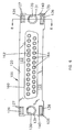
- the preferred embodiment of the present invention comprises a stamped and formed one-piece conductive connector shell 1 that is adapted to be assembled to an insulating connector housing 100 having electrical contacts 200 disposed therein.
- the one-piece conductive connector shell 1 generally comprises a flange 5 (Fig. 2), an annular D-shaped projection 10, and a pair of fastening wings 15.
- flange 5 is substantially planar and includes a front surface 7 and a back surface 9 (Fig. 3). Flange 5 is shaped so as to fully shield a corresponding flange on the insulating connector housing 100, as will hereinafter be disclosed in further detail.
- the annular D-shaped projection 10 extends out of the plane defined by flange 5 (Fig. 4). D-shaped projection 10 is adapted to receive the insulating connector housing 100, as will hereinafter be disclosed in further detail.
- Fastening wings 15 are disposed in spaced-apart relation on the lateral sides of flange 5, so as to be adjacent to the lateral sides of D-shaped projection 10 (Fig. 2).
- Fastening wings 15 are substantially coplanar with flange 5 (Figs. 2, 3, and 4).
- Flange 5 is cut back at its top and bottom edges, adjacent to and inboard of fastening wings 15, so as to further define the upper and lower portions of the fastening wings.
- Fastening wings 15 are adapted to (i) secure one-piece conductive connector shell 1 to the insulating connector housing 100, (ii) electrically fasten one-piece conductive connector shell 1 to a PCB, and (iii) receive mating jackscrews.
- each of the fastening wings 15 comprise upper latching tabs 30, lower grounding tabs 40, and jackscrew mounting apertures 60.
- Each upper latching tab 30 comprises a projection 32 (Figs. 3 and 4). Projections 32 extend rearwardly at a 90 degree angle with respect to fastening-wings 15, and terminate in a free end 33. Projections 32 also include a central portion 35 that is cut out to define an upper retaining latch 36. Upper retaining latch 36 is cantilevered so as to have a forwardly facing free end 38. Upper retaining latch 36 is adapted to be bent upwards out of the plane defined by projection 32 so as to be able to engage a corresponding internal shoulder of a cavity in insulating connector housing 100, as will hereinafter be disclosed in further detail.
- each lower grounding tab 40 comprises a projection 41 (Fig. 2) extending downwardly from a lower edge 42 of each fastening wing 15.
- Projection 41 comprises a central portion 43 that is cut out to define a lower retaining latch 44.
- Lower retaining latch 44 is essentially identical to upper retaining latch 36 disclosed in detail above. More particularly, lower retaining latch 44 is cantilevered so as to have a free end 45 (Figs. 4 and 5).
- Lower retaining latch 44 is adapted to be bent out of the plane defined by projection 41 so as to be able to engage a corresponding internal shoulder of a cavity in insulating connector housing 100, as will hereinafter be disclosed in further detail.
- Lower retaining latch 44 is located adjacent to distal end 47 of projection 41 (Fig. 2).
- Integral boardlocks 50 are disposed at the distal end 47 of each projection 41. Integral boardlocks 50 electrically and mechanically fasten lower grounding tabs 40 to a PCB. They provide an electrical pathway between one-piece conductive connector shell 1 and the electrical traces on the PCB. Integral boardlocks 50 comprise a pair of flexible, elongate tines 51 extending downwardly in spaced-apart relation from the distal end 47 of each projection 41. A slot 54 is defined between tines 51. Tines 51 are spaced inwardly from lateral edges 49 of projection 41. Tines 51 include tip portions 52 at their distal ends. Integral boardlocks 50 further include synclinal ramp surfaces 56 disposed on their outside edges adjacent to tip portions 52. Synclinal ramp surfaces 56 are adapted to mechanically fasten lower grounding tabs 40 to holes in a PCB.
- a pair of jackscrew mounting apertures 60 are laterally disposed adjacent to D-shaped projection 10, between upper latching tabs 30 and lower grounding tabs 40.
- Each jackscrew mounting aperture 60 comprises a tubular projection 62 that is formed in-situ during stamping, so as to project rearwardly out of the plane defined by each fastening wing 15.
- Tubular projections 62 include a plurality of internal threads 64 (Fig. 5). Internal threads 64 are cold-formed in interior surface 66 during the stamping and forming of one-piece conductive connector shell 1.
- one-piece conductive connector shell 1 is typically manufactured in a conventional high-speed stamping press, using a conventional die tool, both of which are well known in the art.
- a flat strip of conductive metal such as a cold rolled steel or the like, is progressively fed into a conventional stamping die tool.
- Flange 5, D-shaped projection 10, and fastening wings 15 are progressively profiled and formed in the metal strip by a plurality of stations located in the die tool.
- the tubular projections 62 are formed in the metal strip as follows. A pair of piercing punch tools pierce the metal strip at the point on each fastening wing 15 where a tubular projection 62 is to be formed. Once a hole is formed in the strip, a punching tool in a subsequent station in the die is forced against the peripheral edges of the pierced hole so as to draw the peripheral edges downwardly, out of the plane of the metal strip. Typically, the punching tool has a diameter somewhat larger than the diameter of the pierced hole. The action of the punch against the peripheral edges of the pierced hole causes the surrounding material to bulge out of the plane defined by fastening wing 15, thus forming each tubular projection 62. Each tubular projection 62 has a central lumen 63 (Fig. 5) that is formed as the punch draws the surrounding material into the pierced hole.
- a tapping head station inserts a rotatable, cold-forming tap into central lumen 63 of tubular projection 62.
- the tapping head station is internally positioned within the die tool and has a geared transmission mechanism that is adapted to hold and rotate the cold-forming tap.
- the geared transmission is adapted to rotate the cold-forming tap in a first direction on a downward stroke of the press and in a second direction on an upward stroke of the press.
- the rotating cold-forming tap enters the tubular projection's central lumen 63 on a downward stroke of the stamping press.
- the rolling action of the tap threads against interior surface 66 of central lumen 63 causes a plurality of internal threads 64 to be formed in the metal.
- internal threads 64 are formed without removing any metal from tubular projection 62.
- a plurality of cold-formed internal threads 64 (Fig. 5) are rolled into interior surface 66 of tubular projection 62 during each stroke of the stamping press. It has been found that the tapping head manufactured by the Adwin Corporation is particularly well suited for this process.
- one-piece conductive connector shell 1 is intended to be used in conjunction with the insulating connector housing 100 so as to form a complete electrical connector. More particularly, insulating connector housing 100 comprises a flange 120, a base portion 140, a D-shaped projection 160, a plurality of mutually-insulated cavities 180 (Fig. 7), and a hood portion 190.
- Flange 120 comprises a front surface 122 (Fig. 6) and a back surface 124 (Fig. 7).
- Upper latching tab receiving apertures 126 (Fig. 6) are disposed in spaced-apart relation on the upper portion of front surface 122.
- Upper latching tab receiving apertures 126 have chamfered edges 127 to facilitate assembly of one-piece conductive connector shell 1 to insulating connector housing 100, as will hereinafter be disclosed in further detail.
- Upper latching tab cavities 128 extend rearwardly through flange 120 from apertures 126 so as to open on back surface 124. Cavities 128 have internal shoulders 129, spaced away from apertures 126, for fixedly engaging the forwardly facing free ends 38 (Fig. 4) of upper latching tabs 30, as will hereinafter be disclosed in further detail.
- Tubular projection receiving holes 130 are disposed in spaced-apart relation on front surface 122, below upper latching tab receiving apertures 126.
- Tubular projection receiving holes 130 extend rearwardly through flange 120 and have chamfered edges 131 to facilitate assembly of one-piece conductive connector shell 1 to insulating connector housing 100.
- Grounding tab receiving apertures 135 are disposed in spaced-apart relation on front surface 122, below tubular projection receiving holes 130. Grounding tab receiving apertures 135 have chamfered edges 136 disposed about their periphery to facilitate assembly of the insulating connector housing 100 to the one-piece conductive connector shell 1.
- insulating connector housing 100 further comprises a base portion 140 that extends rearwardly from the bottom portion of flange 120.
- Base portion 140 comprises a lower mounting face 141 (Fig. 8) that is adapted to sit evenly on a surface of a PCB.
- a pair of grounding tab retaining cavities 142 are disposed in spaced-apart relation within base portion 140.
- Grounding tab retaining cavities 142 extend rearwardly through base portion 140, from grounding tab receiving apertures 135 to an end aperture 137.
- a separating projection 138 (Figs. 7 and 8) is centrally disposed in a tine-receiving slot 139 at the rear bottom edge of each grounding tab retaining cavity 142.
- Tine-receiving slots 139 are radiused at their forward end (Figs. 8, 9, and 10) so that tines 51 may be bent into slot 139. In this way, tines 51 can project downwardly in a substantially perpendicular manner from base portion 140 upon final assembly of one-piece conductive connector shell 1 to insulating connector housing 100 (Fig. 10). Separating projection 138 further ensures that tines 51 are maintained in spaced-apart relation after the bending operation.
- Each grounding tab retaining cavity 142 has an internal shoulder 144 (Fig. 8) spaced away from apertures 135 and 137. Internal shoulders 144 are similar to internal shoulders 129 disclosed above in connection with cavities 128. Internal shoulders 144 are adapted to fixedly engage free ends 45 (Fig. 9) of lower retaining latch 44.
- a plurality of positioning portions 146 extend rearwardly from back surface 124 and are adapted to position electrical contacts in a predetermined pattern.
- the plurality of positioning portions 146 provide alignment and positioning for electrical contacts and facilitate mounting of the complete electrical connector onto a PCB.
- D-shaped projection 160 extends forwardly from front surface 122 of flange 120.
- D-shaped projection 160 is adapted to fit tightly within annular D-shaped projection 10 of one-piece conductive connector shell 1.
- a mating face 162 (Fig. 6) is disposed at the distal end of D-shaped projection 160.
- Mating face 162 further includes a plurality of openings 164 adapted to expose the mating portions of the electrical contacts located therein.
- D-shaped projection 160 and mating face 162 are adapted for mating with a complementary connector during use (not shown).
- Insulating connector housing 100 has a plurality of mutually-insulated cavities 180 (Fig. 7) for receiving electrical contacts.
- the plurality of cavities 180 communicate with mating face 162 via a plurality of openings 164.
- Hood 190 extends rearwardly from flange back surface 124 and is adapted to protect and insulate the electrical contacts.
- insulating connector housing 100 further comprises a plurality of electrical contacts 200 (Fig. 1) that are well known in the art.
- Each electrical contact 200 comprises a PCB mating portion 206 that extends downwardly from insulating connector housing 100.
- PCB mating portion 206 is adapted to be soldered in plated-through holes (not shown) provided in the printed circuit board.
- the PCB mating portion 206 provides an electrical interconnection with traces on the PCB.
- the one-piece conductive connector shell 1 is assembled to insulating connector housing 100 as follows. Lower grounding tabs 40 are first bent back, approximately 90 degrees with respect to fastening wing 15, so as to extend rearwardly from lower edge 42. Next, one-piece conductive connector shell 1 is positioned in front of insulating connector housing 100 so that free ends 33 of upper latching tabs 30 are disposed opposite upper latching tab receiving apertures 126, as seen in Fig. 9. In this position, tips 52 of tines 51 are disposed opposite lower grounding tab receiving apertures 135. One-piece conductive connector shell 1 is then moved toward insulating connector housing 100 so that shell flange back surface 9 engages and completely shields housing flange front surface 122.
- upper retaining latches 36 are driven through upper retaining latch cavities 128 until forwardly facing free ends 38 slip behind and fixedly engage rearwardly facing internal shoulders 129.
- lower retaining latches 44 are driven through grounding tab retaining cavities 142 until forwardly facing free ends 45 slip behind and fixedly engage rearwardly facing internal shoulders 144.
- An advantage of the invention resides in a one-piece conductive connector shell having internally threaded jackscrew mounting apertures that are formed in the shell during a single manufacturing process.
Abstract
Description
Claims (1)
- An electrical connector of the type including a one-piece shell (1) and an insulative connector housing (100) adapted to contain therein a plurality of electrical contacts (200), said one-piece shell (1) including a front shell wall (6), a pair of upper tabs (30), and a pair of lower tabs (40), all of said upper and lower tabs (30, 40) at least initially extending orthogonally rearwardly from said front wall (5) and including latching portions (36, 44) adapted to fasten said one-piece shell (1) to said insulating connector housing (100), and said insulative housing (100) including a pair of upper tab-receiving apertures (126) and a pair of lower tab-receiving apertures (135) all extending orthogonally rearwardly from a front face (122) of said insulative housing (100) at least to rearwardly facing shoulders (129, 144) cooperable with said latching portions (36, 44) of said upper and lower tabs (30, 40) of said one-piece shell (1) upon full insertion into said apertures (126, 135) to retain said shell to said housing, board-mounting sections (50) being joined to said lower tabs (40) the connector characterized in that:end portions (51) of said lower tabs (40) are adjacent central lower tab portions (43) and are initially planar therewith and are located rearwardly beyond said rearwardly facing shoulders (144) of said lower tab-receiving apertures (135) upon full insertion of said lower tabs (40) thereinto, and said end portions (51) include board-retention sections (50) defined thereon enabling mounting of the connector onto a circuit board upon said lower tab end portions (51) being bent downwardly upon full insertion of said lower tabs (40) into said lower tab-receiving apertures (135) to define all said board-retention sections (50) to be inserted into respective mounting holes of a board,whereby said one-piece shell (1) provides for board-mounting of the connector while all of said upper tabs (30) and said central lower tab portions (43) are insulatively covered upon fastening of said one-piece shell (1) to said insulative housing (100).
Applications Claiming Priority (3)
| Application Number | Priority Date | Filing Date | Title |
|---|---|---|---|
| US283130 | 1981-07-14 | ||
| US08/283,130 US5564945A (en) | 1994-07-29 | 1994-07-29 | One-piece conductive connector shell and method for making the same |
| EP95918377A EP0772897B1 (en) | 1994-07-29 | 1995-05-02 | One-piece conductive shell and method for making the same |
Related Parent Applications (1)
| Application Number | Title | Priority Date | Filing Date |
|---|---|---|---|
| EP95918377A Division EP0772897B1 (en) | 1994-07-29 | 1995-05-02 | One-piece conductive shell and method for making the same |
Publications (2)
| Publication Number | Publication Date |
|---|---|
| EP0836250A2 true EP0836250A2 (en) | 1998-04-15 |
| EP0836250A3 EP0836250A3 (en) | 1998-07-15 |
Family
ID=23084665
Family Applications (3)
| Application Number | Title | Priority Date | Filing Date |
|---|---|---|---|
| EP97121968A Withdrawn EP0836250A3 (en) | 1994-07-29 | 1995-05-02 | One-piece conductive shell, and method for making the same |
| EP95918377A Expired - Lifetime EP0772897B1 (en) | 1994-07-29 | 1995-05-02 | One-piece conductive shell and method for making the same |
| EP99107033A Withdrawn EP0940892A3 (en) | 1994-07-29 | 1995-05-02 | One-piece conductive shell and method for marking the same |
Family Applications After (2)
| Application Number | Title | Priority Date | Filing Date |
|---|---|---|---|
| EP95918377A Expired - Lifetime EP0772897B1 (en) | 1994-07-29 | 1995-05-02 | One-piece conductive shell and method for making the same |
| EP99107033A Withdrawn EP0940892A3 (en) | 1994-07-29 | 1995-05-02 | One-piece conductive shell and method for marking the same |
Country Status (8)
| Country | Link |
|---|---|
| US (1) | US5564945A (en) |
| EP (3) | EP0836250A3 (en) |
| JP (1) | JP3413466B2 (en) |
| CN (1) | CN1099730C (en) |
| DE (1) | DE69512920T2 (en) |
| MY (1) | MY112003A (en) |
| TW (1) | TW269750B (en) |
| WO (1) | WO1996004697A1 (en) |
Families Citing this family (10)
| Publication number | Priority date | Publication date | Assignee | Title |
|---|---|---|---|---|
| JP3668584B2 (en) * | 1997-03-19 | 2005-07-06 | 富士通コンポーネント株式会社 | Mounting structure of shield connector |
| US5947769A (en) * | 1997-06-03 | 1999-09-07 | Molex Incorporated | Shielded electrical connector |
| JP3278050B2 (en) * | 1997-06-16 | 2002-04-30 | タイコエレクトロニクスアンプ株式会社 | Shielded connector |
| AU9180698A (en) * | 1997-09-30 | 1999-04-23 | Whitaker Corporation, The | Shielded connector with pcb boardlock |
| JP3479770B2 (en) * | 2000-05-10 | 2003-12-15 | 日本航空電子工業株式会社 | Connector lock structure and mating connector lock structure |
| KR100625971B1 (en) * | 2003-10-10 | 2006-09-20 | 삼성에스디아이 주식회사 | Plasma display device having structures for coupling and grounding of circuit board |
| US7503807B2 (en) * | 2005-08-09 | 2009-03-17 | Tyco Electronics Corporation | Electrical connector adapter and method for making |
| TWM395285U (en) * | 2008-09-15 | 2010-12-21 | Chou-Hsien Tsai | Having metal sheath shell of electrical |
| CN201498677U (en) * | 2009-09-04 | 2010-06-02 | 富士康(昆山)电脑接插件有限公司 | electrical connector |
| JP6634420B2 (en) | 2017-08-28 | 2020-01-22 | 矢崎総業株式会社 | Shield connector for device direct mounting |
Citations (3)
| Publication number | Priority date | Publication date | Assignee | Title |
|---|---|---|---|---|
| EP0180284A2 (en) * | 1984-10-29 | 1986-05-07 | E.I. Du Pont De Nemours And Company | One-piece printed circuit board connector shell |
| WO1988008627A1 (en) * | 1987-04-30 | 1988-11-03 | Amp Incorporated | Electrical connector shielded member having mounting means |
| GB2265768A (en) * | 1992-03-26 | 1993-10-06 | Whitaker Corp | Electrical connector |
Family Cites Families (6)
| Publication number | Priority date | Publication date | Assignee | Title |
|---|---|---|---|---|
| US4034471A (en) * | 1976-05-03 | 1977-07-12 | Western Electric Company, Inc. | Process of isolating bonding material on a terminal plate |
| US4512618A (en) * | 1983-03-10 | 1985-04-23 | Amp Incorporated | Grounding mating hardware |
| US4911659A (en) * | 1989-04-21 | 1990-03-27 | Amp Incorporated | Electrical connector and a retention bracket therefor |
| US4943244A (en) * | 1989-12-26 | 1990-07-24 | Molex Incorporated | Grounding electrical connector |
| US5104326A (en) * | 1991-01-25 | 1992-04-14 | Molex Incorporated | Printed circuit board shielded electrical connector |
| US5158481A (en) * | 1991-09-27 | 1992-10-27 | Amp Incorporated | Shielded electrical connector with torsioned shield interconnect |
-
1994
- 1994-07-29 US US08/283,130 patent/US5564945A/en not_active Expired - Lifetime
-
1995
- 1995-03-17 TW TW084102552A patent/TW269750B/zh not_active IP Right Cessation
- 1995-05-02 DE DE69512920T patent/DE69512920T2/en not_active Expired - Lifetime
- 1995-05-02 EP EP97121968A patent/EP0836250A3/en not_active Withdrawn
- 1995-05-02 CN CN95194965A patent/CN1099730C/en not_active Expired - Fee Related
- 1995-05-02 WO PCT/US1995/005530 patent/WO1996004697A1/en active IP Right Grant
- 1995-05-02 EP EP95918377A patent/EP0772897B1/en not_active Expired - Lifetime
- 1995-05-02 EP EP99107033A patent/EP0940892A3/en not_active Withdrawn
- 1995-05-02 JP JP50646996A patent/JP3413466B2/en not_active Expired - Fee Related
- 1995-07-29 MY MYPI95002194A patent/MY112003A/en unknown
Patent Citations (3)
| Publication number | Priority date | Publication date | Assignee | Title |
|---|---|---|---|---|
| EP0180284A2 (en) * | 1984-10-29 | 1986-05-07 | E.I. Du Pont De Nemours And Company | One-piece printed circuit board connector shell |
| WO1988008627A1 (en) * | 1987-04-30 | 1988-11-03 | Amp Incorporated | Electrical connector shielded member having mounting means |
| GB2265768A (en) * | 1992-03-26 | 1993-10-06 | Whitaker Corp | Electrical connector |
Also Published As
| Publication number | Publication date |
|---|---|
| US5564945A (en) | 1996-10-15 |
| DE69512920T2 (en) | 2000-05-04 |
| EP0772897A1 (en) | 1997-05-14 |
| EP0772897B1 (en) | 1999-10-20 |
| WO1996004697A1 (en) | 1996-02-15 |
| JP3413466B2 (en) | 2003-06-03 |
| CN1099730C (en) | 2003-01-22 |
| EP0836250A3 (en) | 1998-07-15 |
| MY112003A (en) | 2001-03-31 |
| CN1157672A (en) | 1997-08-20 |
| EP0940892A2 (en) | 1999-09-08 |
| TW269750B (en) | 1996-02-01 |
| EP0940892A3 (en) | 1999-10-13 |
| DE69512920D1 (en) | 1999-11-25 |
| JPH10506224A (en) | 1998-06-16 |
Similar Documents
| Publication | Publication Date | Title |
|---|---|---|
| US4718854A (en) | Low profile press fit connector | |
| US6368154B1 (en) | Shielded electrical connector with ground contact spring | |
| US4735575A (en) | Electrical terminal for printed circuit board and methods of making and using same | |
| US5645454A (en) | Right angle coaxial connector and method of assembling same | |
| EP0749185B1 (en) | Electrical connector | |
| EP0393864A1 (en) | Electrical connector and retention bracket therefor | |
| JP2000517459A (en) | Shield member for panel mounting connector | |
| WO2006127071A1 (en) | Press-fit pin | |
| HU217389B (en) | Circuit board, circuit board equipped with edge-mountable connector, and method of mounting an electrical connector to the edge of the circuit board | |
| US5024607A (en) | Grounding electrical connector | |
| US5564945A (en) | One-piece conductive connector shell and method for making the same | |
| EP0499431B1 (en) | Lanced hold-downs | |
| US20040123458A1 (en) | Method of making a straddle mount connector | |
| US5137472A (en) | Means for securing ground plates to electrical connector housing | |
| US20040127097A1 (en) | Ground bus for an electrical connector | |
| US20040180582A1 (en) | Connector terminal, a connector and a mounting method | |
| US4780958A (en) | Method of making an electrical terminal for a printed circuit board | |
| US7086912B2 (en) | Electrical terminal having resistance against mating terminal removal | |
| EP0507166A2 (en) | Grounding electrical connector | |
| CN112909607B (en) | Connector, shielding sheet, grounding contact and jack forming method | |
| JPH07220792A (en) | Female type terminal and manufacture thereof | |
| JP3196116B2 (en) | Shielded electrical connector and manufacturing method thereof | |
| US20030190827A1 (en) | Electrical connector having retention contact tails and non-retention contact tails for retaining to a pcb prior to soldering as well as reducing force of inserting the contact tails to the pcb | |
| DE19941989A1 (en) | Printed circuit card screened electrical connector having cover with inner screening section and internal wiring external pins protruding and having secondary outer cover. | |
| EP0510808B1 (en) | Press fit solder cup |
Legal Events
| Date | Code | Title | Description |
|---|---|---|---|
| PUAI | Public reference made under article 153(3) epc to a published international application that has entered the european phase |
Free format text: ORIGINAL CODE: 0009012 |
|
| 17P | Request for examination filed |
Effective date: 19971212 |
|
| AC | Divisional application: reference to earlier application |
Ref document number: 772897 Country of ref document: EP |
|
| AK | Designated contracting states |
Kind code of ref document: A2 Designated state(s): DE FR GB IT NL |
|
| AX | Request for extension of the european patent |
Free format text: LT PAYMENT 980112;LV PAYMENT 980112;SI PAYMENT 980112 |
|
| PUAL | Search report despatched |
Free format text: ORIGINAL CODE: 0009013 |
|
| AK | Designated contracting states |
Kind code of ref document: A3 Designated state(s): DE FR GB IT NL |
|
| AX | Request for extension of the european patent |
Free format text: LT PAYMENT 980112;LV PAYMENT 980112;SI PAYMENT 980112 |
|
| STAA | Information on the status of an ep patent application or granted ep patent |
Free format text: STATUS: THE APPLICATION IS DEEMED TO BE WITHDRAWN |
|
| 18D | Application deemed to be withdrawn |
Effective date: 19980413 |