EP0836161A2 - Keypad - Google Patents
Keypad Download PDFInfo
- Publication number
- EP0836161A2 EP0836161A2 EP97307539A EP97307539A EP0836161A2 EP 0836161 A2 EP0836161 A2 EP 0836161A2 EP 97307539 A EP97307539 A EP 97307539A EP 97307539 A EP97307539 A EP 97307539A EP 0836161 A2 EP0836161 A2 EP 0836161A2
- Authority
- EP
- European Patent Office
- Prior art keywords
- pressure
- sensitive
- switch
- backing plate
- keypad
- Prior art date
- Legal status (The legal status is an assumption and is not a legal conclusion. Google has not performed a legal analysis and makes no representation as to the accuracy of the status listed.)
- Granted
Links
Images


Classifications
-
- G—PHYSICS
- G07—CHECKING-DEVICES
- G07F—COIN-FREED OR LIKE APPARATUS
- G07F19/00—Complete banking systems; Coded card-freed arrangements adapted for dispensing or receiving monies or the like and posting such transactions to existing accounts, e.g. automatic teller machines
- G07F19/20—Automatic teller machines [ATMs]
- G07F19/201—Accessories of ATMs
-
- G—PHYSICS
- G07—CHECKING-DEVICES
- G07F—COIN-FREED OR LIKE APPARATUS
- G07F19/00—Complete banking systems; Coded card-freed arrangements adapted for dispensing or receiving monies or the like and posting such transactions to existing accounts, e.g. automatic teller machines
- G07F19/20—Automatic teller machines [ATMs]
- G07F19/205—Housing aspects of ATMs
-
- H—ELECTRICITY
- H01—ELECTRIC ELEMENTS
- H01H—ELECTRIC SWITCHES; RELAYS; SELECTORS; EMERGENCY PROTECTIVE DEVICES
- H01H13/00—Switches having rectilinearly-movable operating part or parts adapted for pushing or pulling in one direction only, e.g. push-button switch
- H01H13/70—Switches having rectilinearly-movable operating part or parts adapted for pushing or pulling in one direction only, e.g. push-button switch having a plurality of operating members associated with different sets of contacts, e.g. keyboard
- H01H13/702—Switches having rectilinearly-movable operating part or parts adapted for pushing or pulling in one direction only, e.g. push-button switch having a plurality of operating members associated with different sets of contacts, e.g. keyboard with contacts carried by or formed from layers in a multilayer structure, e.g. membrane switches
-
- H—ELECTRICITY
- H01—ELECTRIC ELEMENTS
- H01H—ELECTRIC SWITCHES; RELAYS; SELECTORS; EMERGENCY PROTECTIVE DEVICES
- H01H2231/00—Applications
- H01H2231/006—Bank automat; Cash register; Vending machine
-
- H—ELECTRICITY
- H01—ELECTRIC ELEMENTS
- H01H—ELECTRIC SWITCHES; RELAYS; SELECTORS; EMERGENCY PROTECTIVE DEVICES
- H01H2239/00—Miscellaneous
- H01H2239/032—Anti-tamper
Definitions
- This invention relates to a keypad, especially a keypad allowing entry of confidential information, such as the keypad of an Automated Teller Machine (ATM) into which a user enters a Personal Identity Number (PIN).
- ATM Automated Teller Machine
- PIN Personal Identity Number
- a known keypad may comprise a matrix of mechanical keys having on their undersides protrusions which apply pressure, when a key is operated, to a pressure-sensitive membrane, which is held by the keypad against a backing plate.
- microswitches within the ATM casing which operate to provide a warning on removal of the backing plate.
- a pressure sensitive keypad comprising an array of mechanically-operable keys; adjacent the array a membrane layer having a plurality of pressure-sensitive areas, each said area corresponding to a key and forming a normally-open electrical switch; a rigid backing plate adjacent to the membrane layer arranged so that manual operation of a key causes pressure to be applied to the corresponding pressure-sensitive area so as to close the corresponding switch; and electrical monitoring means arranged to sense said closure; characterized by at least one further pressure-sensitive area on said membrane; pressure means to apply pressure to said further area when the backing plate is correctly positioned to provide a normally-closed electrical switch; and monitoring means to detect when said switch opens.
- an ATM has a keypad input 2, a display screen 4, a card input slot 6, and a currency dispense slot 8.
- a customer inserts a card into the input slot 6 and keys in a PIN by means of the keys 2.
- the ATM automatically contacts the central authorization point of the financial institution operating the ATM for authorization of the card and PIN; if authorization is confirmed, the customer can request the dispensing of currency notes by the slot 8.
- the ATM is controlled by a processor (not shown).
- a keypad for an ATM comprises a key layer 10 in the form of a molding 12 supporting a 2 X 8 matrix of mechanically-operable keys.
- a pressure-sensitive membrane layer 20 comprising a pressure-sensitive membrane 22 having on it a 2 X 8 matrix of pressure sensitive areas 24 shown as circles and corresponding to the matrix of keys 14, plus four additional pressure sensitive areas 26 shown as rectangles.
- a support layer 30 comprising a backing plate 32 having on its surface adjacent the membrane 22 four protrusions 36 positioned to correspond with the four additional pressure sensitive areas 26.
- the conventional backing plate is provided with a number of apertures in the positions corresponding to the pressure sensitive areas 26, and an additional backing plate, carrying four protrusions 36, is provided.
- the layers 10,20,30 can be clamped together by screws or bolts passing through apertures 18,28,38 at each corner of each layer.
- a protrusion (not shown) on its underside applies pressure to the corresponding pressure sensitive area 24 of the membrane area 22, pressing it against the backing plate 32. Electrically, the normally-open switch corresponding to that key is closed by the pressure, and a monitor circuit identifies the key and passes an appropriate signal to the processor of the ATM.
- the protrusions 36 apply pressure to the additional pressure sensitive areas 26, pressing them against the underside of the molding 22. Electrically, four corresponding switches are normally-closed switches. If the backing plate 32 is removed, the pressure is removed and the switches open, allowing an alarm signal to be provided by known techniques.
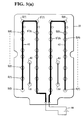
- Fig. 3(a) shows the 2 X 8 matrix of switches, indicated as S(0) to S(F), with each switch having two contact points, such as S(6), S'(6), or S(A), S'(A), to accommodate switch wobble on closure.
- Each switch is indicated by a circle.
- the switches in one line of the matrix are connected in series, S(0) to S(7) to S'(7) to S'(0), by a U-shaped conducting track 40, and switches in the other line of the matrix series, S(F) to S'F) are connected by a second U-shaped conducting track 42.
- One end of the track 40 is connected to one pole of a current source 44, and one end of the track 42 is connected to the other pole.
- the four additional switches 26 in Fig. 2 are shown in Fig. 3(a) as four contact points, A(1) to A(4).
- connections on the lower face ofthe membrane layer 22 are shown as an array of conductors 46 connecting the contacts shown as circles W corresponding to the positions of the pressure-sensitive switches S on the upper face.
- connection pattern is conventional for a 2 X 8 switch array.
- the ends of the conductors 46 terminate in twenty-nine connector pins P(1) to P(29) at one edge of the membrane layer.
- Fig. 3(b) shows schematically connections between three of the pins P and a monitor circuit 48.
- Monitor circuit 48 recognizes that key 2 has been depressed, by known techniques, and sends an appropriate signal over a connection 50 to the processor of the ATM. By several keystrokes, a PIN can be entered, recognized, and authorized by conventional techniques.
- the four additional switches A1-A4 in Fig. (a) correspond with circles B1-B4 in Fig. (b).
- the tracks connecting circles B1-B4 are arranged so that the four switches are connected in series between connector pins P1 and P2.
- the switches are normally-closed switches, and the monitor circuit 48 applies a voltage to cause a current to flow through all of the switches.
- the additional switches may be placed at other positions on the membrane layer 22, for example at its corners. Fewer switches, e.g. 2 switches may be used. Whatever the number of additional switches, they may be connected in series to a current source, or in parallel, as convenient.
- the keypad may be used in systems other than ATMs when a keypad is likely to be attacked to capture its data input.
Landscapes
- Business, Economics & Management (AREA)
- Accounting & Taxation (AREA)
- Finance (AREA)
- Physics & Mathematics (AREA)
- General Physics & Mathematics (AREA)
- Push-Button Switches (AREA)
- Input From Keyboards Or The Like (AREA)
Abstract
Description
Claims (5)
- A pressure sensitive keypad (2) comprising an array of mechanically-operable keys (14); adjacent the array a membrane layer (22) having a plurality of pressure-sensitive areas (24), each said area corresponding to a key (14) and forming a normally-open electrical switch; a rigid backing plate (32) adjacent the membrane layer (22) arranged so that manual operation of the key (14) causes pressure to be applied to the corresponding pressure-sensitive areas (24) so as to close the corresponding switch; characterized by at least one further pressure-sensitive area (26) on said membrane; pressure means (36) to apply pressure to said further area (26) when the backing plate (32) is correctly positioned to provide a normally-closed electric switch (A,B); and monitoring means (48) to detect when said switch (A,B) opens.
- A keypad according to claim 1 characterized in that said pressure means is a protrusion (36) attached to the backing plate (32).
- A keypad according to claim 1 or claim 2 characterized by a plurality of further pressure-sensitive areas (24) arranged as normally-closed switches and connected in series to electrical source means (44).
- A keypad according to claim 3 characterized by a pressure-sensitive membrane layer (22) having on one face a plurality of pressure-sensitive switches (S(0) to S(F)) connected in series by electrically conducting tracks (40,42) across the electrical source means (44); and having on the other face a plurality of corresponding electrical contacts (W(0) to W(F)) connected by electrically conducting tracks (46) to said monitoring means (48).
- A keypad according to claim 4 characterized in that each pressure-sensitive switch (S(0) to S(F)) has two contact positions (S(2), S'(2)) and two corresponding electrical contacts (W(2), W'(2)).
Applications Claiming Priority (2)
| Application Number | Priority Date | Filing Date | Title |
|---|---|---|---|
| GB9620979 | 1996-10-08 | ||
| GBGB9620979.6A GB9620979D0 (en) | 1996-10-08 | 1996-10-08 | Keypad |
Publications (3)
| Publication Number | Publication Date |
|---|---|
| EP0836161A2 true EP0836161A2 (en) | 1998-04-15 |
| EP0836161A3 EP0836161A3 (en) | 2000-02-02 |
| EP0836161B1 EP0836161B1 (en) | 2003-05-28 |
Family
ID=10801118
Family Applications (1)
| Application Number | Title | Priority Date | Filing Date |
|---|---|---|---|
| EP97307539A Expired - Lifetime EP0836161B1 (en) | 1996-10-08 | 1997-09-25 | Keypad |
Country Status (7)
| Country | Link |
|---|---|
| US (1) | US5936557A (en) |
| EP (1) | EP0836161B1 (en) |
| JP (1) | JP4028626B2 (en) |
| DE (1) | DE69722343T2 (en) |
| ES (1) | ES2197310T3 (en) |
| GB (1) | GB9620979D0 (en) |
| ZA (1) | ZA978675B (en) |
Cited By (8)
| Publication number | Priority date | Publication date | Assignee | Title |
|---|---|---|---|---|
| EP1043704A1 (en) * | 1999-04-06 | 2000-10-11 | Ncr International Inc. | Self service terminal |
| FR2825187A1 (en) * | 2001-05-23 | 2002-11-29 | Sagem | Electronic payment keyboard with intrusion detection, in which movement of keyboard cover from its mounted position triggers an intrusion alarm |
| WO2009027472A1 (en) * | 2007-08-28 | 2009-03-05 | Hypercom Gmbh | Safety console |
| DE102008003264A1 (en) * | 2008-01-04 | 2009-07-09 | Demmel Ag | Keypad for e.g. access control keyboard of bank terminal, has safety contact partner producing constant contact with printed circuit board independent from opening-or closing condition of switch contact partner |
| DE102008005442A1 (en) * | 2008-01-22 | 2009-07-30 | Demmel Ag | Input keyboard for e.g. cash-machine, has drill protective foil extending over stroke-actuated areas of keyboard and supporting supports spring-tensioned safety contacts at lower side |
| EP2806409A1 (en) * | 2013-05-21 | 2014-11-26 | NCR Corporation | Encrypting PIN pad |
| EP2764477A4 (en) * | 2011-10-03 | 2015-07-29 | Ezetap Mobile Solutions Private Ltd | A dongle device with tamper proof characteristics for a secure electronic transaction |
| CN112133041A (en) * | 2020-09-28 | 2020-12-25 | 中国银行股份有限公司 | Contactless intelligent ATM |
Families Citing this family (8)
| Publication number | Priority date | Publication date | Assignee | Title |
|---|---|---|---|---|
| US6885317B1 (en) | 1998-12-10 | 2005-04-26 | Eatoni Ergonomics, Inc. | Touch-typable devices based on ambiguous codes and methods to design such devices |
| US6710269B2 (en) * | 2001-07-18 | 2004-03-23 | International Business Machines Corporation | Foil keyboard with security system |
| US7761175B2 (en) | 2001-09-27 | 2010-07-20 | Eatoni Ergonomics, Inc. | Method and apparatus for discoverable input of symbols on a reduced keypad |
| US8200865B2 (en) * | 2003-09-11 | 2012-06-12 | Eatoni Ergonomics, Inc. | Efficient method and apparatus for text entry based on trigger sequences |
| US20080138135A1 (en) * | 2005-01-27 | 2008-06-12 | Howard Andrew Gutowitz | Typability Optimized Ambiguous Keyboards With Reduced Distortion |
| DE102009054877B4 (en) | 2009-12-17 | 2018-06-28 | Cherry Gmbh | keyboard |
| DE202011101259U1 (en) * | 2011-05-23 | 2012-05-30 | Peter Eiba | slots |
| FR3021423B1 (en) * | 2014-05-23 | 2016-06-24 | Cie Ind Et Financiere D'ingenierie Ingenico | CODE KEYBOARD FOR ELECTRONIC TERMINAL KEYBOARD AND CORRESPONDING ELECTRONIC TERMINAL. |
Citations (4)
| Publication number | Priority date | Publication date | Assignee | Title |
|---|---|---|---|---|
| US4644326A (en) * | 1983-06-03 | 1987-02-17 | Secure Keyboards Limited | Unitary key panel |
| US4882779A (en) * | 1984-04-12 | 1989-11-21 | Pengeinstitutternes Kobe - Og Kreditkortaktieselskab | Apparatus for communicating with data systems and a method of communicating with data systems |
| EP0411185A1 (en) * | 1989-08-03 | 1991-02-06 | Scheidt & Bachmann Gmbh | Data input device |
| FR2692419A1 (en) * | 1992-01-24 | 1993-12-17 | Fusilier Jean Marie | Flat keyboard with progressive sensitivity keys for wireless remote control - Uses box made up of number of layers one of which is PCB carrying raised cells which provide progressive actions depending on pressure applied to their overlying keys. |
Family Cites Families (4)
| Publication number | Priority date | Publication date | Assignee | Title |
|---|---|---|---|---|
| US4543563A (en) * | 1982-08-23 | 1985-09-24 | Rca Corporation | Mechanically-actuated transparent touchbars and touchplates |
| US5721666A (en) * | 1995-02-28 | 1998-02-24 | Master Molded Products Corporation | Device panel with in-molded applique |
| US5791459A (en) * | 1996-02-27 | 1998-08-11 | Molex Incorporated | Normally closed electrical switch |
| US5747757A (en) * | 1996-09-10 | 1998-05-05 | Monopanel Technologies, Inc. | Tamper resistant membrane switch |
-
1996
- 1996-10-08 GB GBGB9620979.6A patent/GB9620979D0/en active Pending
-
1997
- 1997-06-25 US US08/883,473 patent/US5936557A/en not_active Expired - Lifetime
- 1997-09-25 DE DE69722343T patent/DE69722343T2/en not_active Expired - Lifetime
- 1997-09-25 EP EP97307539A patent/EP0836161B1/en not_active Expired - Lifetime
- 1997-09-25 ES ES97307539T patent/ES2197310T3/en not_active Expired - Lifetime
- 1997-09-26 ZA ZA9708675A patent/ZA978675B/en unknown
- 1997-10-06 JP JP27243397A patent/JP4028626B2/en not_active Expired - Lifetime
Patent Citations (4)
| Publication number | Priority date | Publication date | Assignee | Title |
|---|---|---|---|---|
| US4644326A (en) * | 1983-06-03 | 1987-02-17 | Secure Keyboards Limited | Unitary key panel |
| US4882779A (en) * | 1984-04-12 | 1989-11-21 | Pengeinstitutternes Kobe - Og Kreditkortaktieselskab | Apparatus for communicating with data systems and a method of communicating with data systems |
| EP0411185A1 (en) * | 1989-08-03 | 1991-02-06 | Scheidt & Bachmann Gmbh | Data input device |
| FR2692419A1 (en) * | 1992-01-24 | 1993-12-17 | Fusilier Jean Marie | Flat keyboard with progressive sensitivity keys for wireless remote control - Uses box made up of number of layers one of which is PCB carrying raised cells which provide progressive actions depending on pressure applied to their overlying keys. |
Cited By (14)
| Publication number | Priority date | Publication date | Assignee | Title |
|---|---|---|---|---|
| US6367695B1 (en) | 1999-04-06 | 2002-04-09 | Ncr Corporation | Self service terminal |
| EP1043704A1 (en) * | 1999-04-06 | 2000-10-11 | Ncr International Inc. | Self service terminal |
| FR2825187A1 (en) * | 2001-05-23 | 2002-11-29 | Sagem | Electronic payment keyboard with intrusion detection, in which movement of keyboard cover from its mounted position triggers an intrusion alarm |
| US8325067B2 (en) | 2007-08-28 | 2012-12-04 | Verifone Gmbh | Security keyboard |
| WO2009027472A1 (en) * | 2007-08-28 | 2009-03-05 | Hypercom Gmbh | Safety console |
| AU2008292124B2 (en) * | 2007-08-28 | 2012-05-24 | Verifone Gmbh | Safety console |
| DE102008003264A1 (en) * | 2008-01-04 | 2009-07-09 | Demmel Ag | Keypad for e.g. access control keyboard of bank terminal, has safety contact partner producing constant contact with printed circuit board independent from opening-or closing condition of switch contact partner |
| DE102008003264B4 (en) * | 2008-01-04 | 2016-07-28 | Demmel Ag | Tamper-proof keyboard with protection against removal of the key caps |
| DE102008005442B4 (en) * | 2008-01-22 | 2011-09-22 | Demmel Ag | Tamper-proof keyboard |
| DE102008005442A1 (en) * | 2008-01-22 | 2009-07-30 | Demmel Ag | Input keyboard for e.g. cash-machine, has drill protective foil extending over stroke-actuated areas of keyboard and supporting supports spring-tensioned safety contacts at lower side |
| EP2764477A4 (en) * | 2011-10-03 | 2015-07-29 | Ezetap Mobile Solutions Private Ltd | A dongle device with tamper proof characteristics for a secure electronic transaction |
| EP2806409A1 (en) * | 2013-05-21 | 2014-11-26 | NCR Corporation | Encrypting PIN pad |
| US9430675B2 (en) | 2013-05-21 | 2016-08-30 | Ncr Corporation | Encrypting pin pad |
| CN112133041A (en) * | 2020-09-28 | 2020-12-25 | 中国银行股份有限公司 | Contactless intelligent ATM |
Also Published As
| Publication number | Publication date |
|---|---|
| ES2197310T3 (en) | 2004-01-01 |
| JPH10228342A (en) | 1998-08-25 |
| EP0836161B1 (en) | 2003-05-28 |
| EP0836161A3 (en) | 2000-02-02 |
| ZA978675B (en) | 1998-03-26 |
| DE69722343T2 (en) | 2004-04-01 |
| GB9620979D0 (en) | 1996-11-27 |
| US5936557A (en) | 1999-08-10 |
| JP4028626B2 (en) | 2007-12-26 |
| DE69722343D1 (en) | 2003-07-03 |
Similar Documents
| Publication | Publication Date | Title |
|---|---|---|
| US5936557A (en) | Keypad | |
| EP1043704B1 (en) | Self service terminal | |
| US9990614B2 (en) | Tactile touch screen | |
| US9911104B2 (en) | Banking system controlled responsive to data bearing records | |
| US20180197157A1 (en) | Banking System Controlled Responsive to Data Bearing Records | |
| US9245702B1 (en) | Keypad having tamper-resistant keys | |
| US20080278353A1 (en) | Tamper resistant electronic transaction assembly | |
| US6097606A (en) | Financial transaction terminal with limited access | |
| AU728108C (en) | An improved method and system for encrypting input from a touch screen | |
| US9564024B2 (en) | Banking system controlled responsive to data bearing records | |
| US9658763B2 (en) | Banking system controlled responsive to data bearing records | |
| US20080296365A1 (en) | Self Service Device with Manipulation Recognition | |
| US9824546B2 (en) | Banking system controlled responsive to data bearing records | |
| US9240291B2 (en) | Rugged keypad | |
| US9251540B1 (en) | Banking system controlled responsive to data bearing records | |
| US9831050B2 (en) | Tamper resistant rugged keypad | |
| US9224273B1 (en) | Banking system controlled responsive to data bearing records | |
| EP1577856B1 (en) | A self-service terminal | |
| US20140351959A1 (en) | Encrypting pin pad | |
| JP4307579B2 (en) | Magnetic card detector | |
| JP3694823B2 (en) | Automatic transaction equipment | |
| US8978971B1 (en) | Banking system controlled responsive to data bearing records | |
| WO1999060533A1 (en) | Financial transaction terminal with limited access | |
| CN209946986U (en) | Keyboard password anti-theft device, ATM keyboard and ATM equipment | |
| US9177449B1 (en) | Banking system controlled responsive to data bearing records |
Legal Events
| Date | Code | Title | Description |
|---|---|---|---|
| PUAI | Public reference made under article 153(3) epc to a published international application that has entered the european phase |
Free format text: ORIGINAL CODE: 0009012 |
|
| AK | Designated contracting states |
Kind code of ref document: A2 Designated state(s): DE ES FR GB IT |
|
| PUAL | Search report despatched |
Free format text: ORIGINAL CODE: 0009013 |
|
| AK | Designated contracting states |
Kind code of ref document: A3 Designated state(s): AT BE CH DE DK ES FI FR GB GR IE IT LI LU MC NL PT SE |
|
| 17P | Request for examination filed |
Effective date: 20000802 |
|
| AKX | Designation fees paid |
Free format text: DE ES FR GB IT |
|
| GRAH | Despatch of communication of intention to grant a patent |
Free format text: ORIGINAL CODE: EPIDOS IGRA |
|
| GRAH | Despatch of communication of intention to grant a patent |
Free format text: ORIGINAL CODE: EPIDOS IGRA |
|
| GRAA | (expected) grant |
Free format text: ORIGINAL CODE: 0009210 |
|
| AK | Designated contracting states |
Designated state(s): DE ES FR GB IT |
|
| REG | Reference to a national code |
Ref country code: GB Ref legal event code: FG4D |
|
| REF | Corresponds to: |
Ref document number: 69722343 Country of ref document: DE Date of ref document: 20030703 Kind code of ref document: P |
|
| REG | Reference to a national code |
Ref country code: ES Ref legal event code: FG2A Ref document number: 2197310 Country of ref document: ES Kind code of ref document: T3 |
|
| ET | Fr: translation filed | ||
| PLBE | No opposition filed within time limit |
Free format text: ORIGINAL CODE: 0009261 |
|
| STAA | Information on the status of an ep patent application or granted ep patent |
Free format text: STATUS: NO OPPOSITION FILED WITHIN TIME LIMIT |
|
| 26N | No opposition filed |
Effective date: 20040302 |
|
| REG | Reference to a national code |
Ref country code: GB Ref legal event code: 746 Effective date: 20080919 |
|
| PG25 | Lapsed in a contracting state [announced via postgrant information from national office to epo] |
Ref country code: IT Free format text: LAPSE BECAUSE OF NON-PAYMENT OF DUE FEES Effective date: 20100925 |
|
| PGFP | Annual fee paid to national office [announced via postgrant information from national office to epo] |
Ref country code: IT Payment date: 20140922 Year of fee payment: 18 |
|
| PG25 | Lapsed in a contracting state [announced via postgrant information from national office to epo] |
Ref country code: IT Free format text: LAPSE BECAUSE OF NON-PAYMENT OF DUE FEES Effective date: 20150925 |
|
| REG | Reference to a national code |
Ref country code: FR Ref legal event code: PLFP Year of fee payment: 20 |
|
| PGFP | Annual fee paid to national office [announced via postgrant information from national office to epo] |
Ref country code: GB Payment date: 20160927 Year of fee payment: 20 |
|
| PGFP | Annual fee paid to national office [announced via postgrant information from national office to epo] |
Ref country code: FR Payment date: 20160926 Year of fee payment: 20 |
|
| PGFP | Annual fee paid to national office [announced via postgrant information from national office to epo] |
Ref country code: ES Payment date: 20160926 Year of fee payment: 20 |
|
| PGFP | Annual fee paid to national office [announced via postgrant information from national office to epo] |
Ref country code: DE Payment date: 20160928 Year of fee payment: 20 |
|
| REG | Reference to a national code |
Ref country code: DE Ref legal event code: R071 Ref document number: 69722343 Country of ref document: DE |
|
| REG | Reference to a national code |
Ref country code: GB Ref legal event code: PE20 Expiry date: 20170924 |
|
| PG25 | Lapsed in a contracting state [announced via postgrant information from national office to epo] |
Ref country code: GB Free format text: LAPSE BECAUSE OF EXPIRATION OF PROTECTION Effective date: 20170924 |
|
| REG | Reference to a national code |
Ref country code: ES Ref legal event code: FD2A Effective date: 20180507 |
|
| PG25 | Lapsed in a contracting state [announced via postgrant information from national office to epo] |
Ref country code: ES Free format text: LAPSE BECAUSE OF EXPIRATION OF PROTECTION Effective date: 20170926 |